Just before this weekend, my AOL 22-4 asynchronous motor with a power of 400 (W), installed in the on-load tap-changer stage switching drive, failed power transformer.
The reason for its failure was an interturn short circuit of the winding. This situation happens extremely rarely, but it still happens sometimes. Operating conditions make themselves felt - increased content of coal dust. Maybe it’s not even a matter of operating conditions, but rather a low-quality wire supplied for engine repairs.
Well, since I had to disassemble a burnt-out electric motor, I decided at the same time to write an article about the asynchronous motor (IM), its application and design.
Use and purpose of blood pressure
IN Lately asynchronous motors are very widely used, both in industry in the form electric drives, ball mills, conveyors, pumps, crushers, drilling and sanding machines, and in everyday life. It is simply impossible to list all areas of application.
Why are they so widely used?
Yes, because they have a number of advantages compared to others electric machines, for example, have high reliability, ease of maintenance and, no less important, they can operate directly from an alternating voltage network.
Device of an asynchronous motor (IM)
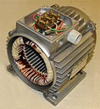
Now let's move on to the design of an asynchronous motor using the example of AOL 22-4 with a power of 400 (W).
I already said a little higher that the AOL 22-4 asynchronous motor is installed in the drive of the on-load tap-changer switching device of the power transformer (17 steps). This is what the drive itself looks like.

The motor is powered from a network with an isolated neutral with a linear voltage of 220 (V).
By the way, this engine was specially modified to suit our needs.
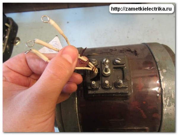
Therefore, on its tag you will see a designation, instead of 220/380 (V), 220/380 (V) (crossed out on the tag 380 and a triangle), i.e. its windings are rewound to a voltage of 127 (V).

Therefore, when line voltage We connect 220 (V) stator windings into a star. Although in principle we do not collect. After the repair, I asked the winding department master to assemble the star inside the motor and connect only 3 pins to the block (terminal) instead of 6.
Asynchronous motor(AD) consists of two parts separated from each other by an air gap. The first part is the stationary stator, and the second part is the moving or rotating rotor.
Both the stator and the rotor consist of a core and a winding. But the stator winding is the primary winding, i.e. is connected to the network, and the rotor winding is secondary. You can read more about this in the article about the operating principle of an asynchronous electric motor.
Structurally, they are divided into 2 types:
- BP s squirrel cage rotor
- IM with wound rotor
My burnt-out AOL 22-4 engine, as you may have guessed, refers specifically to an asynchronous motor with a squirrel-cage rotor.
Squirrel-cage induction motor
The stator of such an engine consists of:
- housings with frame
- core
- three-phase winding
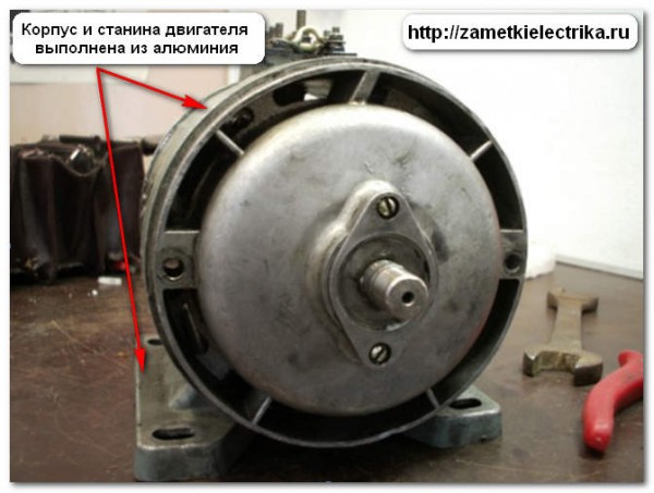
The body itself is most often made of either aluminum alloy or cast iron. In my example, the AOL 22-4 has an aluminum body with an aluminum frame.
The stator core is laminated, i.e. assembled from thin sheets of electrical steel coated with insulating varnish. The thickness of these sheets is approximately 0.35 to 0.5 (mm). This was done in order to reduce the eddy currents that appear during magnetization reversal of the “iron” core under the influence of a rotating magnetic field.
WITH inside In the stator core of an asynchronous motor there are longitudinal grooves into which the winding is placed.
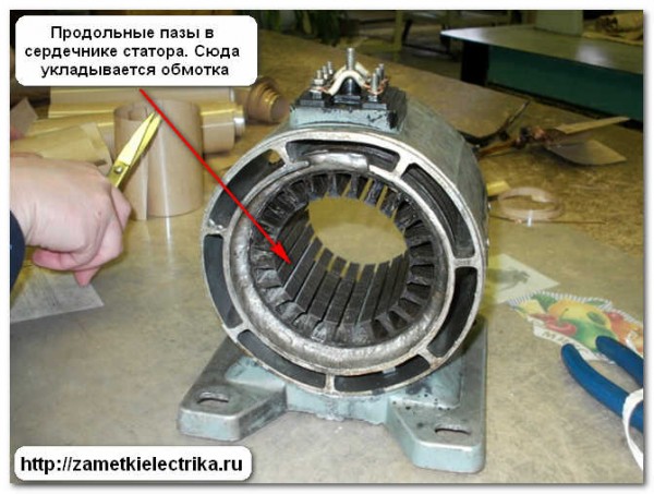
The winding can be either single-layer or multi-layer.
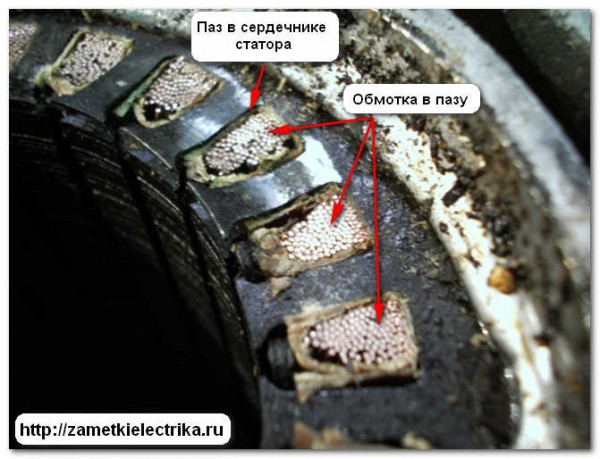
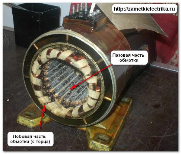
The part of the winding that is located in the slots is called the slot winding.
The grooved parts of the windings outside the core (from the end) are connected to the frontal parts of the windings.
That's all for the stator. Now let's move on to how the rotor is designed. As I said above, the rotor is the rotating part of an asynchronous motor. It consists of a shaft and a core with a short-circuited winding.
By the way, the short-circuited winding of an asynchronous motor is also called a “squirrel wheel”.
The winding of a squirrel-cage rotor consists of a series of aluminum or copper (less commonly) rods, which are located in the grooves of the rotor core. These rods are closed on both sides by short-circuiting rings.
The rotor core, like the stator core, has a laminated design, but its sheets of electrical steel are not coated with varnish, but with a thin film of oxide. This is quite enough to limit small eddy currents due to infrequent magnetization reversal of the core.
In most cases, the short-circuited winding of the IM rotor is performed by pouring the assembled core with molten aluminum alloy. In this case, both short-circuit rings and ventilation blades are cast at the same time.
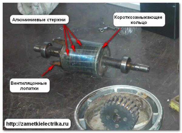
The squirrel-cage rotor shaft rotates on two rolling bearings (they can be seen in the figure above), which are located in bearing shields.

I’ll tell you a few words about cooling an asynchronous motor.
Cooling of asynchronous motors with a power of up to 15 (kW) occurs by blowing the outer surface of the motor using a centrifugal fan. The fan itself is covered with a protective casing with holes for air intake.
Photo of another type of engine.
![]()
Cooling of asynchronous motors with a power of more than 15 (kW), in addition to the method described above, is carried out with internal ventilation. There are special holes in the bearing shields, they are called “blinds”, through which air, with the help of a fan, passes through the internal cavity of the engine. In this case, air penetrates the heated parts of the windings and core, which leads to more efficient cooling.
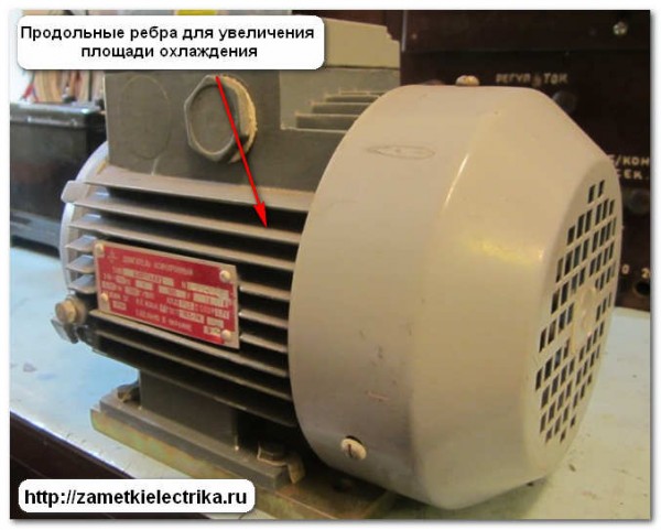
Also, to increase the cooling area, asynchronous motors can have a surface of longitudinal ribs.
To protect people from exposure, an induction motor must be grounded. For this purpose there are special bolts (screws) for grounding. Typically one bolt (screw) is located on the motor housing.
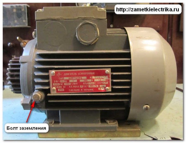
And the other is in the terminal block.

IM with a squirrel-cage rotor has one significant drawback in the form of limited starting torque due to short-circuited rods, which cannot be said about an IM with a wound rotor.
The stator design of a wound-rotor induction motor is similar to the stator design of a squirrel-cage induction motor.

But there is a big difference in the design of the rotor.
The rotor of such an engine has a complicated design. A laminated core with a three-phase winding is attached to its shaft. The beginnings of the windings are connected by a star, and their ends are connected to slip rings. These rings are also located on the rotor shaft and are isolated from the shaft and from each other.
To make contact with the winding of the rotating rotor, two metal-graphite brushes are provided on each ring. The brush is located in a brush holder, which is equipped with springs to provide the necessary force to press the brush against the slip ring.
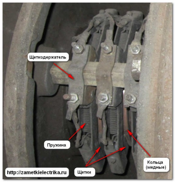
Thus, three-phase winding The rotor is connected to an external starting rheostat, which creates additional resistance in the rotor circuit.
Why this is necessary, you will learn from the following articles in the section “
Three-phase asynchronous motor alternating current used for transformation electrical energy into mechanical energy. It is the most common type electric machines used in industry.
Such an engine consists of three main parts:
- rotor;
- stator;
- housing (casing);
Frame protects the stator and rotor from mechanical damage and serves to secure the moving and stationary parts of an asynchronous motor (IM) in it.
Stator is the stationary part of an asynchronous motor. It consists of a frame and a magnetic circuit. The magnetic core is pressed into the engine frame and forms the electromagnetic core of the stator. The core magnetizes the machine and creates a rotating magnetic field. It is assembled into thin sheets stamped from sheet electrical steel. These sheets are assembled and secured so that stator teeth and grooves are formed in the magnetic circuit. The magnetic core provides low magnetic resistance to the magnetic flux, which increases the magnetic flux of the induction motor. The stator and rotor are separated by an air gap.
Rotor An asynchronous motor is a moving part of an electric machine.
Asynchronous motor stator
The stator is the stationary part of an asynchronous motor. This word is of English origin from the word stator, which in turn has a Latin origin from the word sto - stand. The term stator of an asynchronous motor usually means a combination of several components:
— Bed with feet or flange and longitudinal heat-dissipating fins;
— Core;
— Stator winding;
The stator core is made laminated, assembled from individual stator plates. This is done to reduce losses from eddy currents. Stator plates are stamped from sheets of electrical steel with a thickness of 0.28 to 1 mm. They are isolated from each other by scale. The cores of engines with a rotation axis height of 50-132 mm use cold-rolled unalloyed steel grade 2013. For an engine with an axis height of 160-250 mm, the core is made using cold-rolled lightly alloyed steel grade 2212. In engines with a rotation axis height of 280 to 355 mm , hot-rolled steel grade 1312 is used. The package of stator plates for engines with a rotation axis height of 50 to 60 mm is fastened by welding or using staples, and in engines with a rotation axis height of 200 to 250 mm, exclusively with staples. In engines with a rotation axis height of 280-355 mm, the core sheets are assembled directly in the frame, then they are pressed and secured with special ring keys. This is how the stator part of the magnetic circuit of an asynchronous motor is formed.

Single sheet of stator plate and stack of stator plates of induction motor
Asynchronous motor rotor

The most widely used winding is made in the form of a “squirrel cage”. The system received this name due to the rods with short-circuited rings, which in appearance resemble a wheel of squirrel cages. The rotor winding of large engines includes brass or copper rods, which are driven into the grooves, and short-circuited rings are installed at the ends, to which the rods are soldered or welded. For serial blood pressure low and medium power The rotor winding is made by injection molding of aluminum alloy.

The rotor winding of an asynchronous motor with a wound rotor 3 is wound in the same way as the stator winding 2. The beginning of the rotor winding is connected together and insulated. The ends of such a winding are soldered to slip rings 4, located on the motor shaft using fixed carbon brushes 5; a starting-regulating rheostat can be connected to the slip rings. This scheme allows you to introduce additional resistance into the rotor circuit, thereby regulating the engine speed and sharply reducing starting currents.
Ministry of Science and Education of the Russian Federation
Federal Agency for Education
State educational institution
Higher professional education
National Research
IRKUTSK STATE TECHNICAL UNIVERSITY
Department of Electrical Supply and Electrical Engineering
Three-phase squirrel-cage asynchronous motor
Laboratory report No. 11
by discipline " General Electrical Engineering and electronics"
Completed
Student SMO-11-1 ________ Kopytko Ya.V. 20.10.2012
Associate Professor, Department E and ET ________ Kiryukhin Yu.A. __________
(signature) Last name I.O. (date of)
Irkutsk 2012
Goal 3
1 Brief theoretical information 3
Equipment electrical installation 7
2 Work order 7
3 Calculation part 9
4 Charts 10
Test questions 14
References 17
Goal of the work
Familiarize yourself with the design and principle of operation of a three-phase asynchronous motor with a squirrel-cage rotor and investigate the influence of voltage on the stator fan on its characteristics.
1 Brief theoretical information
1) Design, principle of operation of an asynchronous motor.
An induction motor is an alternating current machine. The word “asynchronous” means not simultaneous. This means that in asynchronous motors the rotational speed of the magnetic field differs from the rotational speed of the rotor. The main parts of the machine are the stator and the rotor, separated from each other by a uniform air gap.
The stator is the stationary part of the machine. In order to reduce losses due to eddy currents, its core is made from stamped sheets of electrical steel 0.35 - 0.5 mm thick, isolated from each other by a layer of varnish. The winding is placed in the grooves of the stator magnetic circuit. In three-phase motors, the winding is three-phase. The winding phases can be connected in a star or triangle depending on the magnitude of the network voltage.
The rotor is the rotating part of the engine. The rotor magnetic core is a cylinder made of stamped sheets of electrical steel. The windings are placed in the rotor slots. Depending on the type of winding, the rotors of asynchronous motors are divided into squirrel-cage and phase (with slip rings). The short-circuited winding consists of uninsulated copper or aluminum rods connected at the ends with rings made of the same material (“squirrel cage”).
The wound rotor has a three-phase winding in the grooves of the magnetic circuit, the phases of which are connected by a star. The free ends of the winding phases are connected to three copper slip rings mounted on the motor shaft. The slip rings are isolated from each other and from the shaft. Carbon or copper-graphite brushes are pressed against the rings. Through slip rings and brushes, a three-phase starting and adjusting rheostat can be connected to the rotor winding.
The conversion of electrical energy into mechanical energy in an asynchronous motor is carried out through a rotating magnetic field. Necessary conditions excitations of the rotating magnetic field are:
spatial shift of the stator coil axes;
temporary shift of currents in the stator coils.
The first requirement is satisfied by the appropriate arrangement of the magnetizing coils on the stator magnetic circuit. The phase axes of the winding are shifted in space by an angle of 120°. The second condition is ensured by applying a three-phase voltage system to the stator coils.
When the motor is connected to a three-phase network, a system of currents of the same frequency and amplitude is installed in the stator winding, periodic changes of which relative to each other occur with a delay of 1/3 of the period.
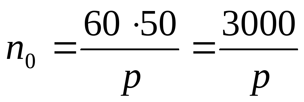
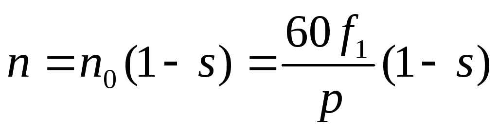
The winding phase currents create a magnetic field rotating relative to the stator with a frequency , rpm, which is called the synchronous motor speed:

Where  - network current frequency, Hz,
р – number of pairs of magnetic field poles.
At standard mains frequency 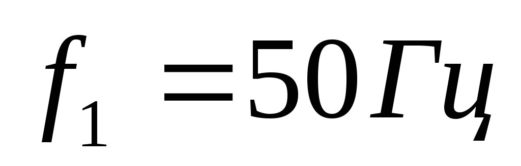 , field rotation frequency
|
|
 , rpm
, rpmWhile rotating, the field crosses the rotor conductors, inducing an EMF into them. When the rotor winding is closed, the EMF causes currents, the interaction of which with the rotating magnetic field produces a rotating electromagnetic torque. The rotor rotation speed in the motor mode of an asynchronous machine is always less than the field rotation speed, i.e. the rotor “lags behind” the rotating field. Only under this condition is an EMF induced in the rotor conductors, current flows and torque is created. The phenomenon of the rotor lagging behind the magnetic field is called slip. The degree of lag of the rotor from the magnetic field is characterized by the magnitude of the relative slip:

where n is the rotor rotation speed, rpm.
For asynchronous motors, slip can vary from 1 (start) to a value close to 0 (idle).
2 ) Starting asynchronous motors.
When starting the engine, the following requirements must be met:
1. Small value starting current;
2. Sufficient starting torque;
3. Smooth increase in speed;
4. Simplicity and cost-effectiveness of start-up.
Depending on the design of the rotor (short-circuit or phase), engine power, and the nature of the load, various starting methods are possible.
For squirrel-cage motors, direct starting and reduced voltage starting are used.
1. Direct start. In this case, the stator winding is connected directly to the network at full voltage. Direct starting is permissible only for asynchronous motors with a squirrel-cage rotor of low and medium power (up to 15-20 kW). However, if the supply network power is significant, this method can be extended to motors of higher power (up to approximately 50 kW).
2.
Low voltage starting
.
The starting current of the motor is proportional to the voltage on the phases of the stator winding  , so the voltage decrease accompanied by a corresponding decrease in starting current. However, this method leads to a decrease in the initial starting torque, which is proportional to the square of the voltage at the phases of the stator winding. Due to the significant reduction in starting torque, this starting method is applicable only at low loads on the shaft.
There are several ways to reduce voltage at the moment of start:
a) for easy starting of medium-power asynchronous motors, which operate normally when the phases of the stator winding are connected by a triangle, reduce the voltage at the terminals of these phases by switching them to a star;
b) with any type of phase connection of the stator winding, the voltage can be reduced using a reactor (three-phase inductive coil) connected in series to the stator winding. It is less economical to reduce the voltage on the stator by connecting resistors in series, because At the same time, they become very hot and additional losses of electrical energy occur;
c) for high-power motors, it is advisable to reduce the voltage using a step-down three-phase autotransformer. This method is better than the previous one, but much more expensive. After the motor rotor accelerates and the current subsides, full mains voltage is applied to the stator winding.
Starting a wound-rotor motor is carried out by connecting a starting rheostat to the rotor circuit. The starting rheostat reduces the initial starting current and at the same time increases the initial starting torque, which can reach a value close to the maximum torque. As the engine accelerates, the starting rheostat is removed.
3) Regulating the rotation speed and reversing the asynchronous motor.
Regulation is a forced change in rotation speed with a constant load on the shaft. The disadvantage of asynchronous motors is their poor controllability. But there are still some regulatory opportunities.
From the slip formula we can obtain an expression for the rotor speed of an asynchronous motor:
From this equality it follows that the rotation speed can be changed in the following ways: by changing the frequency of the stator current , number of pairs of poles p and slip s. The rotor speed can be adjusted by changing the supply voltage . Let's consider these methods.
Regulation by changing the frequency of the stator current
.
Frequency regulation of asynchronous motors is the most promising due to the availability of simple and reliable three-phase thyristor frequency converters, which are connected between the industrial network and the asynchronous motor. When adjusting frequency the engine speed can be smoothly changed so that its maximum value will be tens or hundreds of times higher than the minimum.
Regulation by changing the number of pole pairs p . Switching the number of pole pairs of multi-speed asynchronous motors provides stepwise control of the rotor speed and is economical. It is used in machines with a special design of the stator winding, allowing switching of its coils to a different number of pairs of poles, and also when several alternately switched windings are placed in the grooves of the stator magnetic circuit, made on different number pairs of poles, for example, p = 1 and p = 2.
Regulation by changing the supplied voltage
.
A decrease in voltage causes a decrease in rotor speed. Reduce tension it is possible to include rheostats, autotransformers or adjustable chokes in the stator circuit. This method is used only for low-power motors, since as the voltage decreases, the maximum motor torque, which is proportional to the square of the voltage, decreases. Reducing the maximum torque reduces the stability margin of the engine. In addition, the range of rotation speed control is relatively small.
The control methods listed above are used for asynchronous motors with a squirrel-cage rotor.
For motors with a wound rotor, the rotation speed is regulated by changing the slip. To do this, an adjusting rheostat is included in the rotor winding. As the resistance of the adjusting rheostat increases, the slip increases and the rotation speed decreases.
This method provides a smooth change in rotation speed.
Changing the direction of rotation of the rotor is called reversing. To reverse, you need to swap two wires at the terminals of the stator winding of the motor.