Quite often, the operating mode of auxiliary mechanized equipment requires a reduction in standard rotation speeds. This effect can be achieved by adjusting the speed asynchronous motor with your own hands. How to do this in practice (calculation and assembly), using standard circuits management or homemade devices, let's try to figure it out further.
- Wound rotor motors
What is an asynchronous motor?
AC motors have found quite wide application in various spheres of our life, in lifting, transport, processing, measuring equipment. They are used to transform electrical energy, which comes from the network, into the mechanical energy of the rotating shaft. Most often they are used asynchronous converters alternating current. In them, the rotation speed of the rotor and stator is different. A structural air gap is provided between these active elements.
Both the stator and the rotor have a rigid core made of electrical steel (composited type, made of plates), acting as a magnetic circuit, as well as a winding that fits into the structural grooves of the core. It is the way in which the rotor winding is organized or laid out that is the key criterion for classifying these machines.
Squirrel-cage motors (SCR)
Here, a winding is used in the form of aluminum, copper or brass rods, which are inserted into the grooves of the core and closed on both sides by disks (rings). The type of connection of these elements depends on the engine power: for small values, the method of joint casting of disks and rods is used, and for large values, separate production is used, followed by welding to each other. A typical design of such engines can be seen in the illustration below. The stator winding is connected using delta or star circuits.
Wound rotor motors
Connects to the network three-phase winding rotor, through slip rings on the main shaft and brushes. The “star” scheme is taken as the basis. The figure below shows a typical design of such an engine.

Operating principle and speed of asynchronous motors
Let's consider this issue using the example of ADKR, as the most common type of electric motors in lifting, transport and processing equipment. The mains voltage is supplied to the stator winding, each of the three phases of which is geometrically displaced by 120°. After applying voltage, a magnetic field arises, which creates, by induction, an emf and a current in the rotor windings. The latter causes electromagnetic forces that cause the rotor to rotate. Another reason why all this happens, namely, EMF occurs, is the difference in the speed of the stator and rotor.
One of key characteristics of any ADCR is the rotation frequency, which can be calculated using the following relationship:
n=60f/p, rpm
where f is the frequency of the mains voltage, Hz; p – number of stator pole pairs.
All specifications indicated on a metal plate attached to the housing. But if it is missing for some reason, then the number of revolutions can and should be determined manually using indirect indicators. Typically, three main methods are used:
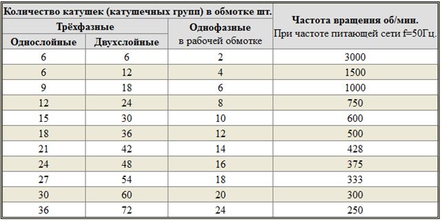
- Calculation of the number of coils. The resulting value is compared with current standards for voltage 220 and 380V (see table below);
- Calculation of revolutions taking into account the diametric pitch of the winding. To determine, a formula of the form is used:
where 2p – number of poles; Z 1 – number of slots in the stator core; y – actually, the step of laying the winding.
Standard speed values can thus be presented in the table:

- Calculation of the number of poles along the stator core. Are used mathematical formulas, where taken into account geometric parameters products:
2p = 0.35Z 1 b / h or 2p = 0.5D i / h,
where 2p – number of poles; Z 1 – number of slots in the stator; b – tooth width, cm; h – backrest height, cm; D i – internal diameter formed by the teeth of the core, cm.
After this, based on the data obtained and magnetic induction, it is necessary to determine the number of turns, which is checked against the motors’ passport data.
Ways to change engine speed
Adjusting the speed of any three-phase electric motor used in lifting and transport machinery and equipment allows you to achieve the required operating modes accurately and smoothly, which is not always possible, for example, due to mechanical gearboxes. In practice, seven main methods of rotation speed correction are used, which are divided into two key areas:
- Change speed magnetic field in the stator. Achieved by frequency regulation, switching the number of pole pairs or voltage correction. It should be added that these methods are applicable to electric motors with squirrel-cage rotor;
- Changing the amount of slip. This parameter can be adjusted by using the supply voltage, connecting additional resistance to electrical circuit rotor, use of a valve cascade or dual supply. Used for models with wound rotor.
The most popular methods are voltage and frequency regulation (through the use of converters), as well as changing the number of pole pairs (implemented by organizing an additional winding with switching capabilities).
Typical speed controller circuits
On the market today you can see a fairly wide selection of regulators and frequency converters for asynchronous motors. However, for domestic needs, lifting or processing equipment can be calculated and assembled on a microcircuit homemade device based on thyristors or powerful transistors.
An example of a circuit of a sufficiently powerful regulator for an asynchronous motor can be seen in the illustration below. Due to this, you can achieve smooth control of its operating parameters, reduce energy consumption by up to 50%, and reduce maintenance costs.
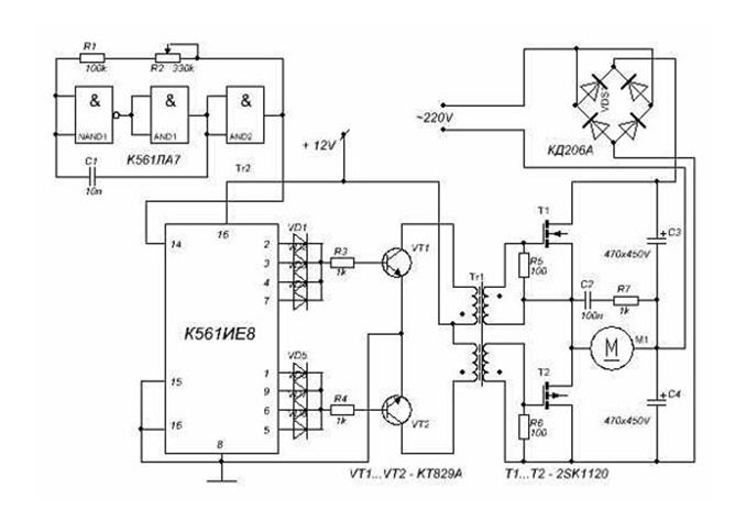
This scheme is complex. For domestic needs, it can be significantly simplified by using a triac, for example, VT138-600, as a working element. In this case, the diagram will look like this:

The motor speed will be regulated by a potentiometer, which determines the phase of the input pulse that opens the triac.
As can be judged from the information presented above, not only its operating parameters, but also the efficiency of the powered lifting or processing equipment depend on the speed of an asynchronous motor. IN trading network Today you can purchase a wide variety of regulators, but you can also make calculations and assemble an effective device with your own hands.
The field will be pulsating. Since the order of switching the inverter outputs can be changed programmatically, it is easy to change the alternation of voltages on the windings, and therefore change the direction of rotation of the motor rotor. Similarly, we will find the beginning and end of the second winding and designate them C2 and C5, and the beginning and end of the third - SZ and C6. On average, for every percent increase in voltage, the consumed reactive power increases by 3% or more (mainly due to an increase in current idle move engine), which in turn leads to increased losses active power in elements electrical network. With such a connection, linear voltage more than the phase voltage by 1.73 times.
This method is the most “ancient”, it is due to the absence, until recently, of frequency regulators and their relatively at a high price. A voltage of 380V is applied between the ends of the windings AB, BC, CA.
Rotation regulator asynchronous electric motor 220V acts as a device that changes the rotation speed of the pump impeller and the output pressure (it regulates almost the entire possible power range - NOT FREQUENCIES!).
On some motors, the ends of the winding phases are brought out onto the terminal board. How the windings are connected to one or another configuration is shown in the figures below.
To change the direction of rotation of a three-phase electric motor, it is necessary to swap any two of the three phases at the point where the power is connected to the motor.
Motors with power over 1.5 kW require a connection and a starting capacitor. However, these crimp rings are lost. First, the belonging of the wires to the individual phases of the stator winding is determined.
The diagram of the launcher is shown in the figure below.
Often there is a need to connect a three-phase electric motor in a subsidiary farm, but there is only a single-phase network (220 V).
Asynchronous electric motors come in two main types: with a wound rotor and with a squirrel-cage rotor, the difference between which lies in the different designs of the rotor winding. This happens because we connect a 3-phase motor to a single-phase network. The primary winding contains 120 turns of wire with a diameter of 0.7 mm, with a tap from the middle, the secondary winding contains two separate windings of 60 turns of the same wire. The voltage value ultimately depends on the characteristics of the machine and the capacitance of the capacitors. It is known that the resistance of a cold filament of an incandescent lamp is 10 times less than the resistance of a hot filament.
If you turn on the IM in a 1-phase network, the torque will be created by only one winding.
In this case, the motor windings are connected in series. When the light comes on, it means that the 2 terminals belong to the same phase. Tags K1 and H3 (or H2) are placed on the terminals located in common knots (tied during the first part of the work) with H1 and K3, respectively. In order to create it, it is necessary to shift the phases on the windings using a special circuit.
Capacitors were used like KBG-MN or others with an operating voltage of at least 400 V. When the generator was turned off, there was electric charge, so they were securely fenced to avoid electric shock.
To connect the motor according to a rather rare star circuit at startup, with subsequent transfer to a delta circuit for operation in operating mode. The engine begins to make a characteristic sound (hum). The motor is switched from one voltage to another by connecting the windings. You should not overload the engine and work “day and night”.
If the engine still hums after this, then this phase should also be set as before, and the next phase should be turned - II.
The disadvantages are: reduced and pulsating torque single phase motor; increased heating; not all standard converters are ready for such work, because... Some manufacturers directly prohibit the use of their products in this mode.
If you use the dimmer in accordance with its purpose and comply with all conditions of use, you can achieve good results for controlling light sources indoors and outdoors.
Instructions
Regardless of how the induction motor is connected to the network, turn off the power to the device in which it is installed. If there are high-voltage capacitors, discharge them before touching any parts of the device.
Be sure to make sure that changing the direction of rotation will not lead to failure or accelerated wear of the device that includes the electric motor.
If a three-phase motor is powered by single-phase network through a capacitor, first be sure to make sure that the load on its shaft is small, and that when changing the direction of rotation it will not increase. Remember that increasing the load with this power supply method can lead to engine shutdown and subsequent fire. Then disconnect the terminal of the capacitor that is connected not to the engine, but to one of the supply wires, from it and switch to another supply wire. If there is a second, starting capacitor, do the same with it (keeping the start button connected in series with it).
If the motor is powered through a three-phase inverter, do not make any switching. Find out from the instructions for the device how to reverse (by moving a jumper, pressing a button, changing settings through the menu or using a special key combination, etc.), and then carry out the actions described there.
Nowadays, asynchronous units are used mainly in motor mode. Devices with a power of more than 0.5 kW are usually made three-phase, while those with less power are single-phase. Over their long existence, asynchronous motors have found wide application in various industries and Agriculture. They are used in the electric drive of hoisting and transport machines, metal-cutting machines, conveyors, fans and pumps. Less powerful engines used in automation devices.
You will need
- - ohmmeter
Instructions
Take three-phase asynchronous engine. Remove the terminal box. To do this, use a screwdriver to unscrew the two screws that secure it to the case. The ends of the motor windings are usually connected to a 3 or 6 terminal block. In the first case, this means that the phase stator windings connected by triangle or star. In the second, they are not connected to each other. In this case, their correct connection. Star switching involves combining winding terminals of the same name (end or beginning) to the zero point. When connecting with a triangle, you should connect the end of the first winding to the beginning of the second, then the end of the second to the beginning of the third, and then the end of the third to the beginning of the first.
Take an ohmmeter. Use it when the terminals of the windings of an asynchronous electric motor are not marked. Determine three windings with the device, designate them conventionally I, II and III. Connect any two of them in series to find the beginning and end of each winding. File them AC voltage a value of 6 - 36 V. Connect an AC voltmeter to the two ends of the third winding. The appearance of alternating voltage indicates that windings I and II were connected in accordance; if it is not there, then in opposite directions. In this case, swap the terminals of one of the windings. Then mark the beginning and end of windings I and II. To determine the beginning and end of the third winding, swap the ends of the windings, say II and III, and repeat the measurements using the method described above.
Connect a phase-shifting capacitor to a three-phase asynchronous motor, which is connected to a single-phase network. Its required capacity (in μF) can be determined using the formula C = k*Iph/U, where U is the voltage of a single-phase network, V, k is a coefficient that depends on the connection of the windings, Iph is the rated phase current of the electric motor, A. Keep in mind that when the windings of an asynchronous electric motor are connected by a “triangle”, then k = 4800, by a “star” - k = 2800. Apply paper capacitors MBGCH, K42-19, which must be designed for a voltage no less than the supply voltage. Remember that even with a correctly calculated capacitor capacitance, asynchronous electrical engine will develop power no more than 50-60% of the nominal.
Sources:
- Connecting a three-phase asynchronous motor to a single-phase network
An asynchronous machine is a device that runs on electricity with alternating current, and the rotational speed of the machine is not equal to the rotational frequency of the magnetic field, which is created as a result of the stator winding current. So what types are there? similar devices and on what principle do they work?
![]()
Instructions
In some countries, such devices are also classified as collector machines and are also called asynchronous induction, which is explained by the process during which the current in the rotor winding is induced by the stator field. Modern world found application in asynchronous machines as electric motors, which convert electrical energy into mechanical force.
The great demand for such devices is explained by their two advantages - easy and fairly simple manufacturing and the absence of electrical contact in the rotor with the stationary part of the machine. But asynchronous machines also have their disadvantages - this is a relatively small Starting torque and significant inrush current.
The history of the creation of asynchronous devices goes back to the Englishman Galileo Ferraris and Nikola Tesla. The first in 1888 published his own research, which outlined theoretical basis similar engine. But Ferrares was mistaken in believing that an asynchronous machine has low efficiency. In the same year, an article by Galileo Ferraris was read by the Russian Mikhail Osipovich Dolivo-Dobrovolsky, who already in 1889 received a patent for a three-phase asynchronous motor, designed like squirrel cage rotor"squirrel wheel" It is this trio that pioneered the era of mass use of electric machines in industry, and now asynchronous devices are the most common motors.
The principle of operation of asynchronous devices is to supply alternating voltage through the windings with current and further create a rotating magnetic field. The latter, in turn, affects the rotor winding, in accordance with the law of electromechanical induction, and interacts with the stator field, which rotates. The result of these actions is the impact on each tooth of the magnetic circuit
Hello, dear readers and visitors of the Electrician's Notes website.
In the last article we talked about it, got acquainted with the diagram of its connection to an electrical network with a voltage of 220 (V), the designation and marking of the terminals.
In the same article, I promised to tell you in the near future about how you can organize its reverse, i.e. control the direction of rotation of the motor remotely, and not using jumpers in the terminal box.
So let's get started.
In principle, there is nothing complicated. The principle of the control circuit is similar, with the exception of some details. Actually, I had never encountered a reverse circuit for single-phase motors before, and this was the first time I had put this circuit into practice.
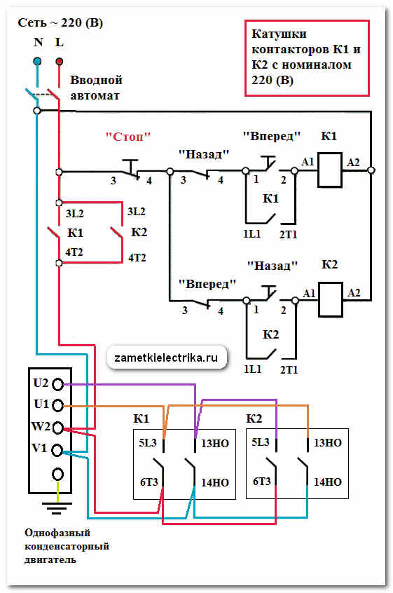
The essence of the circuit comes down to changing the direction of rotation of the shaft of a single-phase capacitor motor remotely using buttons (button station). Remember, in the previous article we manually changed the position of two jumpers on the motor terminal block to change the direction of the working winding (U1-U2). Now you need to remove these jumpers, because... their role in this circuit will be performed by normally open (NO) contacts of the contactors.
Preparing equipment for reversing a single-phase motor
To begin with, we list all the electrical equipment that we need to purchase to organize the reverse of the AIRE 80S2 capacitor motor:
1. Circuit breaker
We use two-pole 16 (A), with characteristic “C” from IEK.

There are 3 buttons in this button post:
- forward button (black)
- back button (black)
- stop button (red)

Let's look at the push-button post.

We see that each button has 2 contacts:
- normally open contact (1-2), which closes when you press the button
- normally closed contact (3-4), which is closed until the button is pressed
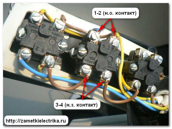
Please note that in the photo the outermost button on the left is upside down. If you connect the reverse circuit of a single-phase motor yourself, then be careful, the buttons in the push-button post may be upside down. Refer to the contact markings (1-2) and (3-4).
3. Contactors
You also need to purchase two contactors. In my example, I use small-sized contactors KMI-11210 from IEK, which are installed on a DIN rail. These contactors have 4 normally open (NO) contacts and are capable of switching loads up to 3 (kW) at an alternating voltage of 230 (V). So they are just right for us, because... Our tested single-phase motor AIRE 80S2 has a power of 2.2 (kW).
Instead of contactors, you can purchase them, using the example of which I described their structure and principle of operation.
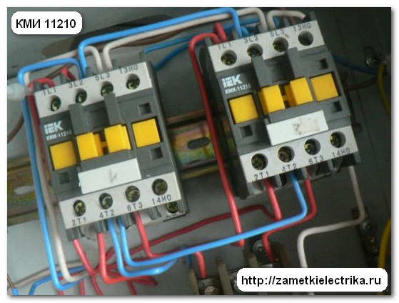
The coils of this contactor are designed for an alternating voltage of 220 (V), which will need to be taken into account when assembling the reverse control circuit for a single-phase motor.
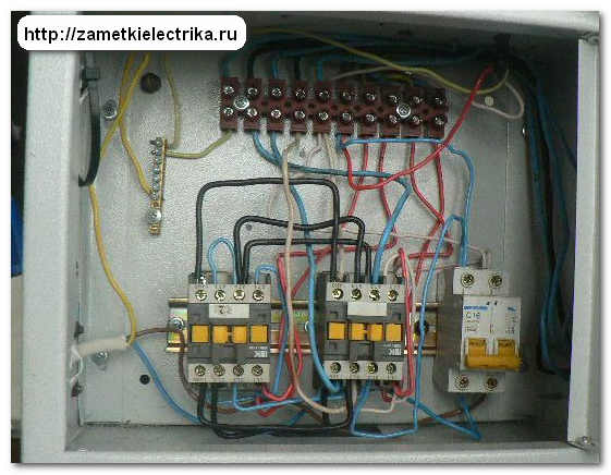
Here, in fact, is my work.
I already said in the previous article that one of the readers of the site “Notes of an Electrician” named Vladimir asked me to help him with a power of 2.2 (kW) and draw up (come up with) a reverse circuit for him. Based on my sketches (including installation ones), Vladimir assembled the above diagram in . A little later he emailed me to say that he tested the circuit, everything works, no complaints.
If you have any questions about the site materials, then ask me in the comments or on . Within 12-24 hours, or maybe faster, it all depends on how busy I am, I will answer you.
Now I will tell you how this scheme works.
Operating principle of a single-phase motor reverse circuit
First of all, turn on the power supply.
1. Forward rotation
When you press the “forward” button, the coil of contactor K1 receives power through the following circuit: phase - NC. contact (3-4) of the “stop” button - n.c. contact (3-4) of the “back” button - n.o. contact (1-2) of the pressed “forward” button - contactor coil K1 (A1-A2) - zero.
Contactor K1 pulls up and closes all its normally open (NO) contacts:
- 1L1-2T1 (self-recovery of coil K1)
- 5L3-6T3 (simulates jumper U1-W2)
- 13NO-14NO (simulates jumper V1-U2)
There is no need to hold down the “forward” button, because... the contactor coil K1 is “self-retaining” through its own n.o. contact (1L1-2T1).
The single-phase motor begins to rotate in the forward direction.
2. Reverse rotation
When you press the “back” button, the coil of contactor K2 receives power through the following circuit: phase - NC. contact (3-4) of the “stop” button - n.c. contact (3-4) of the “forward” button - n.o. contact (1-2) of the pressed “back” button - contactor coil K2 (A1-A2) - zero.
Contactor K2 operates and closes its following normally open (NO) contacts:
- 1L1-2T1 (self-pickup coil K2)
- 3L2-4T2 (phase to motor in power circuit)
- 5L3-6T3 (simulates jumper W2-U2)
- 13NO-14NO (simulates jumper U1-V1)
There is no need to hold the back button with your finger, because... the contactor coil K2 is “self-retaining” through its own n.o. contact (1L1-2T1).
The single-phase motor begins to rotate in the opposite direction.
To stop the engine, you need to press the “stop” button.
3. Blocking
The presented reverse circuit of a capacitor single-phase motor has a button lock, i.e. If, when the engine is turned on in the forward direction, you mistakenly press the “back” button, then contactor K1 will first turn off, and then contactor K2 will work. And vice versa. Thus, we have a blocking from two simultaneously switched on contactors K1 and K2.
You can use other types of locks, but I limited myself to this one.
P.S. This concludes my article. If you liked my article, I will be very grateful if you share it on in social networks. And also don’t forget to subscribe to my new articles - it will be more interesting later.
Before choosing a connection diagram for a single-phase asynchronous motor, it is important to determine whether to reverse. If for proper operation you will often need to change the direction of rotation of the rotor, then it is advisable to organize reversal using a push-button station. If one-way rotation is enough for you, then it will do without the possibility of switching. But what to do if, after connecting via it, you decide that the direction still needs to be changed?
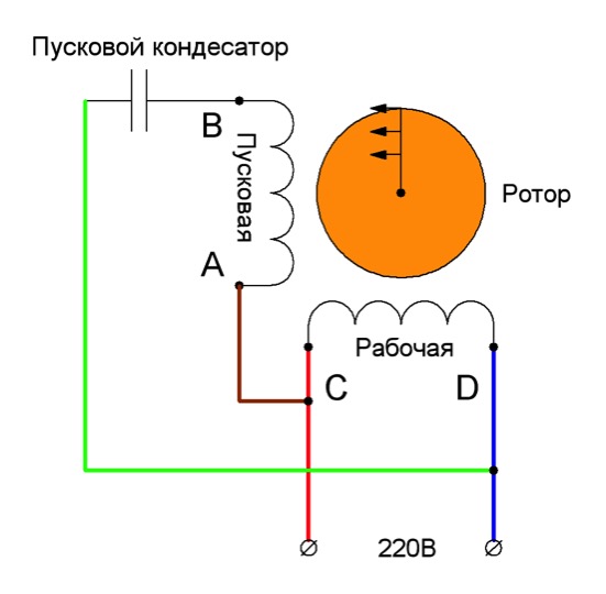
Let's assume that an asynchronous single-phase motor, already connected using a starting-charging capacity, initially has a shaft rotation directed clockwise, as in the picture below.
Let's clarify the important points:
- Point A marks the beginning starting winding, and point B is its end. A brown wire is connected to the starting terminal A, and a green wire is connected to the ending terminal.
- Point C marks the beginning of the working winding, and point D marks its end. A red wire is connected to the initial contact, and a blue wire is connected to the final contact.
- The direction of rotation of the rotor is indicated by arrows.
We set ourselves the task of reversing a single-phase motor without opening its housing so that the rotor begins to rotate in the other direction (in in this example counterclockwise). It can be solved in three ways. Let's take a closer look at them.
Option 1: reconnecting the working winding
To change the direction of rotation of the motor, you can only swap the beginning and end of the working (permanently on) winding, as shown in the figure. You might think that to do this you would have to open the case, take out the winding and turn it over. There is no need to do this, because it is enough to work with the contacts from the outside:
- There should be four wires coming out of the housing. 2 of them correspond to the beginnings of the working and starting windings, and 2 to their ends. Determine which pair belongs only to the working winding.
- You will see that two lines are connected to this pair: phase and zero. With the motor turned off, reverse the phase by changing the phase from the initial winding contact to the final one, and zero - from the final to the initial one. Or vice versa.

As a result, we get a diagram where points C and D change places with each other. Now the rotor of the asynchronous motor will rotate in the other direction.
Option 2: reconnecting the starting winding
The second way to organize reverse asynchronous motor 220 Volts - swap the beginning and end of the starting winding. This is done by analogy with the first option:
- Of the four wires coming out of the motor box, find out which of them correspond to the starter winding taps.
- Initially, end B of the starting winding was connected to the beginning C of the working winding, and beginning A was connected to the starting-charging capacitor. You can reverse a single-phase motor by connecting the capacitance to terminal B, and the beginning of C to the beginning of A.
After the actions described above, we get a diagram as in the figure above: points A and B have swapped places, which means the rotor began to turn in the opposite direction.
Option 3: changing the starting winding to the working winding, and vice versa
Organize reverse single-phase motor 220V in the ways described above is possible only on the condition that taps from both windings with all beginnings and ends come out of the housing: A, B, C and D. But there are often motors in which the manufacturer intentionally left only 3 contacts outside. In this way, he protected the device from various “homemade products”. But still there is a way out.
The figure above shows a diagram of such a “problematic” motor. It only has three wires coming out of the housing. They are marked in brown, blue and purple flowers. The green and red lines corresponding to the end B of the starting winding and the beginning C of the working winding are interconnected internally. We will not be able to access them without disassembling the engine. Therefore, it is not possible to change the rotor rotation using one of the first two options.
In this case, do this:
- Remove the capacitor from the initial terminal A;
- Connect it to the final terminal D;
- Taps are made from wires A and D, as well as the phase (you can reverse it using a key).
Look at the picture above. Now, if you connect the phase to tap D, the rotor rotates in one direction. If phase wire transfer to branch A, you can change the direction of rotation in the opposite direction. Reversing can be done by manually disconnecting and connecting the wires. Using a key will help make the job easier.
Important! Last option reverse circuit The connection of the asynchronous single-phase motor is incorrect. It can only be used if the following conditions are met:
- The length of the starting and working windings is the same;
- Their cross-sectional area corresponds to each other;
- These wires are made of the same material.
All these quantities affect resistance. It must be constant at the windings. If suddenly the length or thickness of the wires differ from each other, then after you organize the reverse, it turns out that the resistance of the working winding will become the same as it was before for the starting winding, and vice versa. This may also cause the engine to fail to start.