An electrical circuit is usually called an electrical circuit through which current flows. A circuit can consist, for example, of a battery that powers a light bulb, or of many elements connected to each other, for example, in your computer. The circuit can consist of an unlimited number of elements and the current always enters one contact at the beginning of the circuit and exits one contact at the end of the circuit.
For reference:
Many people refer to an open circuit as a short circuit. It must be clearly understood that a short circuit is essentially a bridge (jumper) for the passage of current along the shortest path at the place of the circuit, bypassing some of the elements of the entire electrical circuit.
Usually a short circuit has a very small resistance - this leads to the flow of a large current from the power supply (may disable it). If the power wire is directly connected to ground (the option of shorting the plus and minus of the power source is possible), the fuse usually blows, and if there is none, the power source may burn out. This is the short circuit.
If something turns on and stops working again when you move the circuit elements, this is called an open circuit and the break occurs exactly at the moment when the device is not working. That is, the current does not flow and the circuit does not work.

The movement of current and the movement of an electron in DC circuits
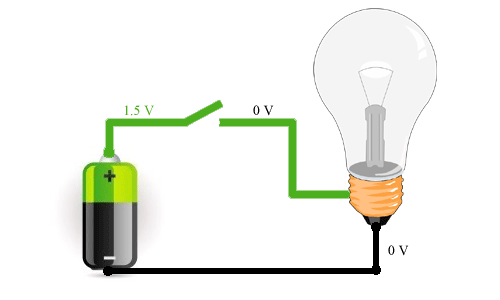
In the picture above you can see how electricity and how electrons move. As you can see, the electrons move from the minus (negative terminal of the power supply) to the positive (positive terminal). This is how electric current actually moves. Most of the time, people assumed that charge carriers were positively charged particles, which means they had to move from positive to negative contact. This is how the usual movement of current is usually imagined. If it is easier for you to imagine that the current flows from plus to minus, then there is nothing to worry about, it does not change the essence of the process.
In alternating current circuits, the polarity of the current source is constantly changing, so in such a circuit, electrons move both in the forward and in the opposite direction. In other articles on our website, we will talk more about direct and alternating current.
Hi all. I am very glad that you have visited my site. And today, we will talk about what a short circuit is and what kind of circuits are.
Short circuit- this is a connection (contact) of two or more points (conductors) of an electrical circuit with different potential values.
Different potentials - this is when the phase and zero in the network alternating current, or plus and minus in the network direct current.
Now let's look at what types of short circuits are.
IN single-phase network There can only be two types of short circuit:
1. phase and zero - this type of closure is very common in simple living conditions. For example, with the onset of winter it becomes cold, and many people try to keep warm with the help of electric heaters.
But few people pay attention to the sockets that include these same heaters. It often happens that the sockets are not designed for the currents that the heaters consume, or often there may be poor contact in the sockets.
Because of this, sockets and plugs begin to warm up. As a result of prolonged heating, the insulation of the wires is destroyed. And at one fine moment, two, already bare, conductors can touch, and a short circuit will result.

2. phase and grounding - this is when phase wire, somehow comes into contact with the grounded body of any electrical equipment. Either electric water heater, lamp, machine tool and so on.
It also happens that the case can be zeroed, then such a short circuit can be attributed to the first case.
But in situations in which a short circuit occurs, there can be much more:
1. single-phase short circuit- phase and zero. I already described this view above, so let's move on to the next one.
2. two-phase - this is when two phases are connected to each other. Happens often on overhead lines power lines. Such a phenomenon, probably, every person has seen in his life. When on the street strong wind and starts loosening the wires, and gets a little salute. In industrial enterprises, such a short circuit often occurs in power circuits.

3. two-phase and earth - this, of course, happens less often, but it still happens. An example when two phases can be connected to each other, and at the same time also contact the ground.
4. three-phase - this is when all three phases are somehow closed to each other. Such a short circuit will occur when a conductive object falls or touches all three phases at the same time.
What are the consequences of short circuit currents.
In the event of a short circuit, the current instantly increases, which leads to strong heating and melting of the metals. Splashes of this metal scatter in all directions, and all this is accompanied by a bright flash and fire. Which can easily lead to a fire and very serious consequences.
In normal home conditions, if you do not choose the right protection against short circuits, then you can really lose a lot. Starting from housing and furniture, and ending with my life and the lives of people living with you under the same roof.

In enterprises, short-circuit currents can lead to emergencies, damage to equipment, and people can also suffer from this. But enterprises usually use several protections at once, which practically eliminates the occurrence of short circuits.
That's all I wanted to say. If you have any questions, then ask them in the comments. If the article was useful to you, then share it with your friends in in social networks and subscribe for updates. See you again.
Sincerely, Alexander!
A short circuit occurs when current-carrying parts of different potentials or phases are connected to each other. A short circuit can also form on the equipment case that is connected to the ground. This phenomenon is also typical for electrical networks and electrical receivers.
Causes and effects of short circuit current
The causes of a short circuit can be very different. This is facilitated by wet or aggressive environment, which deteriorates significantly. A closure can result mechanical influences or human error during repairs and maintenance.
The essence of the phenomenon lies in its name and is a shortening of the path along which the current passes. As a result, current flows past the resistive load. At the same time, it increases to unacceptable limits if the protective shutdown does not work.
However, power outage may not occur even if there are protective equipment. This situation occurs when the short circuit is very far away and significant resistance makes the current insufficient to trip. protective devices. However, this current is enough to ignite the wires and start a fire.

In such situations great importance have the so-called time-current characteristics inherent in circuit breakers. Here, current cutoff and thermal releases that protect against overloads play an important role. These systems are completely different time operation, therefore, the slow action of thermal protection can lead to the formation of a burning arc and damage to conductors located nearby.
Short-circuit currents have an electrodynamic and thermal effect on equipment and electrical installations, which ultimately leads to their significant deformation and overheating. In this regard, it is necessary to pre-calculate the short-circuit currents.
How to calculate the short circuit current using the formula
The calculation of these currents, as a rule, is made if it is necessary to check the operation of the equipment in extreme situations. The main purpose is to determine the suitability of protective automatic devices. In order to correctly calculate the short-circuit current, first of all, it is necessary to know exactly the metal from which the conductor is made. For calculations, you will also need the length of the wire and its cross section.
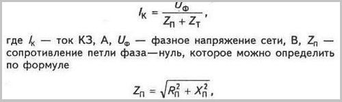
For determining resistivity it is necessary to know the indicator of active resistance Rp, the value of which consists of the resistivity of the wire multiplied by its length. The value of the inductive resistance Xp is calculated from the specific inductive resistance, taken as 0.6 Ohm / km.
The Zt exponent is full resistance phase winding installed in the transformer from the side low voltage. Thus, timely preliminary calculations will help to avoid serious damage to electrical equipment caused by a short circuit.

Calculations make it possible to accurately determine which circuit breaker provide the most effective protection from closures. However, all the necessary measurements can be made using a special device, which is just designed to determine these quantities. To carry out the measurement, the device is connected to the network and switched to the required mode.
Network short circuit protection
The calculation of short-circuit currents (SC) is necessary to select equipment and check the elements of electrical installations (tires, insulators, cables, etc.) for electrodynamic and thermal stability, as well as the settings for protection operation and checking them for response sensitivity. The calculated type of short circuit for selecting or checking the parameters of electrical equipment is usually considered a three-phase short circuit. However, to select and check the settings of relay protection and automation, it is also necessary to determine asymmetric short-circuit currents.
The calculation of short-circuit currents, taking into account the actual characteristics and actual modes of operation of all elements of the power supply system, is complex. Therefore, to solve most practical problems, assumptions are introduced that do not give significant errors:
three-phase network is assumed to be symmetrical;
load currents are not taken into account;
capacities are not taken into account, and consequently, capacitive currents in air and cable networks;
saturation is not taken into account magnetic systems, which allows us to consider constant and current-independent inductive resistances of all elements of a short-circuited circuit;
transformer magnetizing currents are not taken into account.
Depending on the purpose of calculating short-circuit currents, choose calculation scheme networks, determine the type of short circuit, the location of the short circuit points on the circuit and the resistance of the elements of the equivalent circuit. The calculation of short-circuit currents in networks with voltages up to 1000 V and above has a number of features, which are discussed below.
When determining short-circuit currents, as a rule, one of two methods is used:
named units method - in this case, the circuit parameters are expressed in named units (ohms, amperes, volts, etc.);
relative units method - in this case, the circuit parameters express
in shares or percentages of the value taken as the main (basic).
The method of named units is used in calculating short-circuit currents of relatively simple electrical circuits with a small number of transformation steps.
The method of relative units is used when calculating short-circuit currents
in difficult electrical networks with several stages of transformation connected to the district power systems.
If the calculation is performed in named units, then in order to determine the short circuit currents, it is necessary to bring all electrical quantities to the voltage of the step at which the short circuit occurs.
When calculating in relative units, all quantities are compared with the base ones, which are taken as the base power of one GPP transformer or a conventional unit of power, for example, 100 or 1000 MVA.
As the base voltage, the average voltage of the stage at which the short circuit occurred is taken ( U cp = 6.3; 10.5; 21; 37; 115; 230 kV). The resistance of the elements of the power supply system lead to the basic conditions in accordance with the table. 3.1.
Table 3.1
Average specific values of inductive resistances
air and cable lines power transmission
The following types of electrical circuit malfunctions are possible - short circuits (short circuit) and breaks.
Short circuit. It is understood as the connection between "positive" and "minus" current conductors (wires of two or more phases of the AC network) in addition to the consumer electrical energy. K. z. possible in both high and low voltage circuits. There is a short circuit. both by direct contact with open (non-insulated) parts of the conductors, and as a result of damage to their insulation due to breakdown into its depth or overlap electric arc along the insulating surface. An incomplete short circuit may occur when the short circuit is in the circuit. it turns out that part of the resistor or other consumers is turned on.
The emergence of short circuit possibly due to bad condition insulation of current-carrying parts, their contamination, ingress of foreign metal objects ( spanners, files, wire remnants, etc.) on current-carrying parts, breakage of individual bare current-carrying parts (for example, a flexible shunt), overvoltage (atmospheric or switching, i.e., caused by violations of the accepted circuit switching sequence). For collector electric machines, short circuit can occur as a result of a violation of switching, including with strong boxing of wheel sets. K. z. inside the battery can occur both due to the poor condition of the rubber covers of the cells, and due to excess and leakage of electrolyte during recharging. A special case leading to a short circuit can be considered the loss of blocking properties by semiconductor rectifiers.
The consequences of k.z. In all cases of high current flow thermal effect current leads to damage (burning out) of parts at the site of occurrence of short circuit, as well as increased heating of their insulation in the entire area through which such a current flowed. Subsequently, it is possible to. elsewhere in the chain, especially when high humidity atmospheric air. The most serious possible consequence k.z. - fire.
Ways to eliminate a short circuit. The easiest way is to eliminate the damaged 1 element of the circuit - the traction motor, auxiliary machine, a separate apparatus, and in a critical case, the whole section of the electric locomotive. However, in some cases, the consequences of short-term can be reduced while maintaining sufficient operability of the electric locomotive by creating an electrical circuit bypassing the damaged area or by putting (placing) a new temporary insulation instead of the damaged one, removing the short circuit from the place. foreign object, etc. Methods for identifying the place of short circuit. are discussed below.
Chain break. The causes of breaks in the electrical circuit can be: mechanical damage (strong tension or a sharp bend in the wire, cable, bus, weak fastening of their end, frequent fluctuations, for example, between body wires), burning out of the wire or soldering it from the tip, strong oxidation of the contacts or the ingress of a foreign insulating object between them. In a battery, an open circuit occurs when the jumpers are broken or the contacts are oxidized, the electrolyte flows out of the cells.
A blown fuse can also be considered an open circuit, regardless of the cause that caused it. An open circuit also occurs when the drive of any device fails, both due to a decrease in the voltage of the control circuit, and in the event of mechanical damage, as well as due to a decrease in air pressure.
The consequences of circuit breaks are of a different nature than short circuit, but still quite serious: the pantograph does not rise, circuit protection devices do not turn on, traction motor circuits are not assembled or auxiliary machines. In all these cases, the train stops, which leads to a failure in the movement of trains and indirectly poses a threat to the safety of their movement.
Ways to eliminate breaks. In high-voltage circuits with high currents, restoration of a broken section is usually difficult due to the large cross-sectional area of wires (tires, shunts), therefore, most often such a section is either turned off entirely or “bypassed” due to existing parallel circuits without any complicated switching; only if the electric locomotive has adapter brackets, jumpers, such a section can be partially or completely restored. If the break is caused by a non-closing of the contacts of the device due to a malfunction of its drive, in many cases they can be closed forcibly.
When a low-voltage circuit is broken (disturbed), depending on the pitchfork, damage occurs differently; sometimes it is enough just to move and clean the oxidized or burnt contact, in other cases a jumper should be placed, shunting the dangling section. If the tip of the wire is broken or soldered out, then the end of the wire is protected and attached to the clamp instead of the removed tip. The jumper to be installed must be insulated along its entire length, with the exception of its ends, the cores of which must be carefully twisted and stripped before connection. The cross-sectional area of the current-carrying part of the jumper must correspond to the cross-sectional area of \u200b\u200bthe wire whose circuit is broken. If the jumper is long, then it should be fixed in several places from vibrations and possible contact with both high-voltage circuits and grounded parts.
Methods for detecting damage to an electrical circuit. Many violations of the circuits and malfunctions of the apparatus are detected by the driver or his assistant without any special instruments. With knowledge of the circuits and design of apparatuses and sufficient care, most problems are quickly identified by observing measuring instruments, signal lamps and equipment located in the cab. In more difficult cases they ring the circuits with a test lamp or a voltmeter, and in depot conditions and turnover points - with an ohmmeter.
Feature matching method. To quickly find a fault, it is very important to be able to compare the various emerging symptoms, which is possible with sound knowledge and everyday systematic study of circuits and devices. Feature matching - this method of troubleshooting is valuable because, under operating conditions, the use of other methods requires significant time, stopping the electric locomotive and lowering the pantograph. Therefore, the possibility of their application is usually very limited.
The main features taken into account and compared in troubleshooting include the following:
The value of the current recorded by the ammeter before and after the occurrence of a malfunction;
The value of the voltage in the network and on the engines;
Vibrations of instrument arrows;
The position of the controller handles and control buttons;
Movement speed;
Indications of signal lamps;
The value of pressure in pneumatic lines;
Shutdown of devices;
External signs (sparks, smoke, smells, changes in the nature of noise);
Voltage on the battery or generators, etc.
Special cases electrical circuit malfunctions. In addition to obvious breaks and short circuits in the circuits, we will consider cases similar in consequences to them, but slightly different in reasons.
Connecting wires to each other. Violation of the insulation of the wires leads to the connection of their conductive cores. Most often, such damage occurs in places where the wires are bent, where they are connected to devices, it is also possible that the tips of adjacent wires touch each other at the clamps on the clamp rails, broken shunts, for example, at the contactor elements of the controller.
In a high-voltage circuit, such a failure usually results in serious damage, similar to that caused by a short circuit. In low-voltage circuits, the connection of wires is detected by the untimely operation of one or another device. It is important to establish which wires are connected - supply (positive) or outlet, ground (negative).
So, turning on the button Kn1 leads to the excitation of coils 1 and 2, although normally coil 2 should not be excited. By turning on the apparatus associated with coil 2, they judge the short circuit of the supply wires. If it is difficult to find the place of the circuit, then, depending on the purpose of the device 2, it is either turned on constantly, or turned off, or, by disconnecting the coil from the faulty circuit, power is supplied to it from the third circuit , closed by contact C. The fuse link Pr1 usually does not burn out, since an increase in current at parallel connection the second coil is small.
It is possible to short-circuit the negative wires without causing any deviations from the normal mode. . Sometimes a short circuit of the wires can occur, leading to the excitation, for example, of coil 1 when the Kn1 button is turned on, even if the BC auxiliary contact is in the open position. It is difficult to detect such a mutual connection of wires, therefore, often a conductor is connected to the coil and at the same time the ends of the short-circuited conductor are disconnected from the terminals of the devices to which it is connected. If the junction of the wires is found, then in order to isolate them from each other, rubber, dry cardboard, etc. are placed.
As can be seen from both examples, the mutual connection of the wires of the control circuit is sometimes no less dangerous than a short circuit.
Undervoltage of a low-voltage power source (generator or battery). It leads to disconnection (or not inclusion) at first of individual, and then of all devices with an electromagnetic drive, i.e., to the analysis of circuits; all such drives are designed for the lowest voltage of 35 V (ZHR radio station for 40-50 V). The low voltage of the main current source is recognized by the readings of the voltmeter of the control circuit and the ignition of the signal lamp ROT or ZB (on electric locomotives with TRPSH), and at night by the decrease in the incandescence of the lighting lamps and the searchlight.
Reduced air pressure. In the pneumatic control circuit, reduced pressure leads to the shutdown (or not switching on) at first of individual, and then of all devices with a pneumatic drive. Such malfunctions occur when the cranes of the control line are not switched correctly before leaving with the train. They are discovered by dismantling the chains on the first stage, and sometimes right there at the station. Most serious consequence This is the burning of the contacts of one or more contactors, since as the air pressure decreases, the contacts of the contactors slowly diverge under current. A strong decrease in pressure also leads to the lowering of the pantograph during movement.
Jamming of the shafts of anchors (rotors) of electrical machines. Such a malfunction leads to a significant increase in current in them and the operation of protective relays (overload, thermal) or the burning of the fuse insert. It should be noted that an increase in current may not cause the operation of protective devices such as differential relays or grounding relays, since at the beginning of the process the wire insulation is not yet overheated and there is no ground fault. Repeated operation of RP, TRT, blown fuse requires attention to the nature of the work electrical machine protected by this machine.
For traction motors, anchor jamming (wheel set, gear train) at high speed leads to an all-round fire on the surface of the collector and the transfer of the arc to the skeleton, therefore, the relays DR and BV are additionally triggered on a DC electric locomotive and RZ and GV on AC electric locomotives. However, at a low speed of movement on DC electric locomotives, the operation of the DR and BV does not occur, which disorients the driver, and after repeated activation of the protection at high speed, he switches to movement with a decrease in it. As a result, potholes may appear on the wheel tires, the insulation of the traction motor will be overdried, and damage to the wheels may occur.
Thus, if the armature (rotor) of any machine does not rotate or the rotation speed is clearly below the norm (by ear), the engine electrical circuit should be turned off, the wheelset should be hung out at the station.
49 . General order actions in the event of damage to electrical circuits and checking the circuits with a test lamp.
General procedure. In the event of a malfunction in electrical circuits, you can recommend to the driver next order actions: even while moving, compare the signs of damage, stop the train, observing safety measures, make an external inspection of the devices and machines included in the planned
to test the circuit; if necessary, check the sequence; ring the chains; determine the extent and nature of damage; repair damage as much as possible
Checking electrical circuits control devices(lamps, voltmeters, electric bells, ohmmeters, etc.) are conventionally called continuity. It is performed to determine the location of an open or short circuit in electrical circuits when external signs not enough.
Most often, continuity of circuits on an electric locomotive is carried out using a test lamp - a conventional electric lamp rated for a voltage of 50 V, with a two-pin Svan cartridge and two wires. These wires are insulated, and their ends are bare and stripped to a length of 0.5-1 cm. The length of one wire is at least 1.5-2 m, and the other is 0.5 m. It is recommended to pre-solder the crocodile clip to the short end. Lamp power does not exceed 15-25 W; at higher power, the resistance of its filament may turn out to be much less than the resistance of the circuit under test, and the glow of the lamp will not be noticeable.
Checking circuits for open circuits. Basic rules for checking: the chain should be fully assembled, if possible, as it corresponds to the factory scheme; the circuit under test is conditionally divided into two approximately equal (according to the number of elements: auxiliary contacts, clamps, etc.) sections; after making sure that there is no break on one of them, the other untested section is also conditionally divided into two approximately identical sections, etc. The point of such divisions can be a clamp on the rail, an output at the auxiliary contact, the drive coil of the device. As a rule, such a method in the analysis of long chains gives the fastest result.
When checking, three methods can be used: applying voltage to the beginning of the analyzed circuit, applying voltage to one of the wires of the test lamp, and with some precautions and the method of shorting individual sections with a jumper.
Checking the low voltage circuit for an open circuit. Let us assume that any individual contactor does not turn on, in the drive coil circuit of which there are several auxiliary contacts (Fig. 89). If this is a contactor with an electro-pneumatic drive, then by pressing the valve button, the serviceability of the pneumatic part of the drive is checked, as well as the presence compressed air. Turning on the device by pressing its button confirms that the pneumatic part is working. Then they check the serviceability of the control lamp, for which its wire with a crocodile clip is connected to the elements of the low-voltage circuit connected to the plus of the battery, and the other to the body of the electric locomotive. Lighting up the lamp indicates that it is working.
As a plus, in the high-voltage chamber of DC electric locomotives, auxiliary contacts of the BV-1 or BV-2 high-speed switch and some relays are used when the corresponding button is turned on; on electric locomotives BJI10, wires K50, K51, K53, etc. are constantly energized. The downside is a copper air pipe or any part of the high-voltage chamber frame that has been cleaned of paint.
Fig.26. Scheme of dialing the control center with a control lamp.
Let it be necessary to establish where the coil circuit is broken (Fig. 26, a). The short wire of a serviceable control lamp is connected to the "ground" (minus), and the long ones touch the points marked in the figure with letters.
Let's start the test from the middle of the coil circuit, while counting the contacts a-b controller turned on (but it is not known whether they have mutual contact); we connect a long wire to the terminal d of the coil: if the lamp lights up, chain b-d serviceable, if it does not light up, then no; if the lamp lights up, then we touch the output of the coil e - the lamp lights up with a dim light - once again indicates the health of the circuit to the coil, and in addition, the health of the coil itself and the absence of a circuit from point e to the "ground", etc.
If, when point d is touched, the lamp does not light up, then we attach the output of the lamp to point c; if it burns, but does not burn at contact d, then, obviously, the circuit in the auxiliary contact c-d is broken.
Let's check the same circuit by the second method, that is, by applying voltage to the lamp output (Fig. 26, b). If, when point d is touched, the lamp lights up dimly, then the circuit from daughter d to the "ground" is working; reconnect the output of the lamp to point B, and the lamp burns dimly again, the output is a broken circuit on section a-b. Continuing to analyze, we find the place of damage (probably broken contact a-b or a break in the wire b-c).
Let's check the circuit by the third method (without a lamp). Attaching the Ends insulated wire(at one end its crocodile clip can be attached to the shaft of a screwdriver with an insulated handle) to points in-d(or e-i), the drive of the device P is activated - the faulty section is found; it may be more convenient to connect contacts b and e (when contacts in-d are located at the other end of the electric locomotive, and points b-d are nearby).
Using this method, you can make the following mistake: by connecting the ends of the test wire to points e or Ms., in best case we will cause the fuse to blow, in the worst case, we will get burns of the hand or face, i.e., the ends of the conductors should not be connected to sections of the circuit on opposite sides of the consumer (coil P), the coil P in this case has an internal break.
These methods can be used to check the circuits of the drive coils of all low-voltage devices of any electric locomotive, however, the coil circuit of a 4g GV AC electric locomotive can be checked either by the third method or, using a test lamp, by the first method from the push-button switch in the cab (coil resistance 1140 Ohm). As for the coil circuit of high-voltage relays, their resistances are very different and, in addition, in their circuits in most cases there are high-resistance resistors, and not auxiliary contacts, so the use of these methods is usually difficult.
Checking the high voltage circuit for an open circuit. Test lamps are not suitable for testing circuits with high resistances. This applies to checking the health of additional resistors of voltmeters, safety valve circuits, boxing and overvoltage relays, an electricity meter, since they have resistances of tens, hundreds and even thousands of times great resistance control lamp. To check such circuits, ohmmeters or other special measuring instruments are used.
Breaks in the power circuit of traction motors or auxiliary machines can also be detected using a lamp, since the own resistance of each element of the circuit and the entire circuit as a whole is much less than the resistance of the lamp, even if its power is not 15, but 50 W. On DC electric locomotives, the place of the break is specified by the method already described, by artificially attaching the plus of the battery to the beginning of the circuit under test. You can also apply the method of shorting sections.
As already mentioned, in order to more quickly find a break in long chains, they start checking from the middle of the suspected section, rather than immediately checking half of the chain. The half in which the cliff is found is, in turn, divided approximately in half.
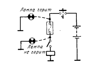
Assume a DC electric locomotive, on the 1st position of the main handle of the controller does not start, although the quick-acting switch and the roof disconnector are turned on, the reverser shafts turn normally and the line contactors turn on, the on-load tap-changer lamp is on; all these signs indicate a break in the power circuit of the traction motors.
With the pantograph lowered, but the BV turned on, a plus is applied by some conductor to the lead-in terminals of the BV arcing coils or the free terminals of the bus disconnector (Fig. 27, a). Then, having connected the short wire of the control lamp to the "ground" (to the body), the end of the long wire touches various points of the circuit, leaving the main handle of the controller in the 1st position. If at the moment point B is touched, the lamp is on, but when point D is touched, it is not, then, therefore, a break occurred in the section of the circuit C-D.
Fig.27. The scheme of continuity of the high-voltage circuit with a control lamp.
This method has the following drawback. If the circuit is accidentally restored at the place of the break, a complete or partial short circuit of the battery may occur. Therefore, more often the test is carried out by the second method: voltage is applied to one wire of the control lamp, and the other is touched by various points in the circuit (Fig. 27, b). In the event of a break in section C-D the lamp will not light when the wire touches point C, and will light up when point D is touched, since this point is connected to "ground" through the rest of the power circuit. It is convenient to use motor cut-off blades as points for connecting the lamp wire.
You can apply another method. Having connected the control lamp with one wire to the plus of the battery, connect it with the other to the bus disconnector knife and then dial the positions with the controller.
If the lamp lights up in one of the rheostat positions serial connection, then, then, an open in the starting resistors (or their connections), and if the lamp lights up after switching to a series-parallel connection, then an open in the windings of the traction motors; it is also possible that the cable suitable for the line contactors, to the 32-0 contactor, to one of the reverser contactor elements, as well as to the terminals (from the "ground" side) of the last traction motors according to the scheme, has burned out.
Check circuits for short circuits. In most cases, the protective device protects not one, but several electrical circuits, therefore, having received one or another signal about its operation or blown fuse, the first actions of the driver will always be:
a) turning off all suspected circuits;
b) protection restoration (fuse replacement);
c) sequential switching on of those sections of the circuit, the damage of which could cause the protection to operate;
d) repeated operation of the protection when one of the circuits is turned on narrows the search area.
In some cases, the search can be stopped, for example, if the protection is triggered when one of the compressors is turned on; clarification of the nature of the damage can be postponed until arrival at one of the nearest stations.
Repeatedly turning on individual sections of the circuit, the driver observes the change in the readings of the signal lamps. However, even the presence a large number signal indicators (lamps, blinker flags) for devices still do not always accurately indicate the location of the damage.
In most cases, grounding one of the points in the circuit of traction motors, reversers, brake switches, excitation weakening resistors, you can drive the train further by shorting the RZ blocking in the circuit of the holding coil of the GV and by disconnecting the AC coil of the ground relay; to strengthen the monitoring of the operation of electrical equipment.
On DC electric locomotives, the most fast method finding a short circuit in the traction motor circuit is as follows: turn off all the motor knives and, connecting one wire of the control lamp to the battery positive, touch all the switched-off OD (OM) knives in turn, first on one section, then on the other (VL10). Lighting of the lamp indicates damage to the circuit of one or another engine.
For further clarification of the location of the short circuit. the section disconnected on both sides is divided into two parts, laying insulation or disconnecting the cable. In the case under consideration, if the lamp lights up when the wire touches point a, to further clarify the location of the damage, disconnect the pole windings from 1 armature winding (insulate under the reverser contacts).
Since at the point of a short circuit the value of the transient resistance can be approximately the same as that of the test lamp, and even higher, its filament may not glow until it glows, so you should use a low-voltage voltmeter installed on switchboard. To do this, the voltmeter wire is disconnected from the battery minus (the body of the electric locomotive), then it is increased and the bare end touches the current-carrying parts of that section of the circuit in which a short circuit is suspected (Fig. 28).
In the event of a short circuit in low-voltage circuits, a fuse blows or a circuit breaker trips. Before replacing the fuse (before the circuit breaker is restored), the driver turns off the button (toggle switch) through which the damaged circuit was fed. After replacing the fuse (switching on; automatic), you should turn on (and turn off) the suspected circuits one by one; having identified such a circuit, it is no longer turned on, the protection is restored and any temporary solution is taken or further troubleshooting begins. To do this, the suspected area is divided into separate small circuits, laying insulation from electric cardboard, thick paper, disconnecting the wire tip, etc.
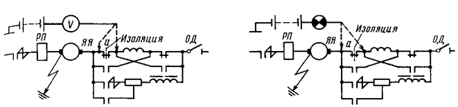
Fig.28. Diagram of the continuity of the circuit sections on K.Z. test lamp and voltmeter.
After that, a control lamp specifies the location of the damage. If a short circuit is suspected in a wire connected to inter-electric locomotive circuits designed to control a system of many units (and on eight-axle electric locomotives VL10, VL10U - with passing from one body to another), then either disconnect the inter-electric cables, or disconnect all the wires of this number from the clamp on the rail and ring them separately (Fig. 29), and then, connecting one wire of the control lamp to the "plus", touch the others in turn ends of these wires. If the lamp comes on at full glow, it will indicate a short circuit in this wire. If the lamp lights up with an incomplete glow, then the wire is normally connected to the "ground" through the coil of the device included in the circuit of this wire. The tip of the damaged wire is isolated, and the rest are re-attached to the rail clamp.
If the wire going to the inter-electric connections turned out to be disconnected, then the control of one electric locomotive (one or two sections) is not disturbed, and if the wire going to the controller in one of the cabs or from the terminal rail to the device is disconnected, then the device is left disconnected or it is forcibly turned on mechanically. In some cases, you can use the backup wires available in bundles of wires or conduits.
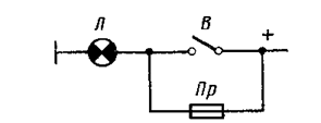
The condition of the fuses, if necessary, is found out by replacing them or checking with a test lamp. To do this, one wire of the lamp is connected to the “ground” (Fig. 30). If, when the other wire touches one fuse cap, the lamp lights up, and when the other is touched, it does not light up, then the fuse insert has blown (except for the negative fuse of the battery). In the case when, to check the integrity of the fuse, it is replaced with a serviceable one, at the time of removing and setting the fuses, their circuit must be opened by the corresponding control circuit button, knife switch or switch.
On some electric locomotives there are special clamps in the circuit of the L1 lighting lamp PSC, shunted by switch B (Fig. 95). By inserting the tested fuse PR into the free clamps and turning off the switch B, by burning the lamp L, they make sure that the fuse is in good condition.
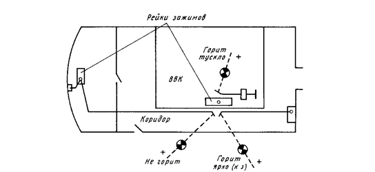
Fig.29. search K.Z. in a low voltage circuit.
Rice. 30. Check fuses.