The main reason for the disruption of the normal operation of the power supply system (PSS) is the occurrence of short circuits (SC) in the network or electrical equipment due to damage to the insulation or improper actions of the maintenance personnel. To reduce the damage caused by the failure of electrical equipment during the flow of short-circuit currents, as well as to quickly restore the normal operation of the solar power plant, it is necessary to correctly determine the short-circuit currents and select electrical equipment, protective equipment and means of limiting short-circuit currents.
short circuit is called a direct connection between any points different phases, phase and neutral wire or phase to ground, not provided for by the normal operating conditions of the installation.
The main types of short circuits in electrical systems Oh:
3. Single-phase short circuit, at which one of the phases is shorted to a neutral wire or ground. Symbol single-phase short circuit points  Currents, voltages, powers and other quantities related to a single-phase short circuit are indicated
  ,
, ,
, etc.
etc.
There are other types of short circuits associated with wire breaks and simultaneous short circuits of wires of various phases.
A three-phase short circuit is symmetrical, since with it all three phases are in the same conditions. All other types of short circuits are asymmetric, since with them the phases do not remain in the same conditions, as a result of which the systems of currents and voltages turn out to be distorted.
When a short circuit occurs, the total electrical resistance of the power supply system circuit decreases, as a result of which the currents in the branches of the system increase sharply, and the voltages in certain parts of the system decrease.
Elements of electrical systems have active and reactive (inductive or capacitive) resistances, therefore, in the event of a sudden disruption of normal operation (in the event of a short circuit), the electrical system is an oscillatory circuit. The currents in the branches of the system and the voltages in its individual parts will change for some time after the occurrence of a short circuit in accordance with the parameters of this circuit. Those. during the short circuit in the circuit of the damaged section, a transient process occurs.
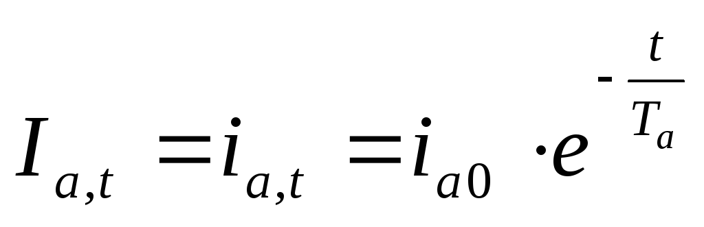
During a short circuit in each of the phases, along with the periodic component of the current (component of the current of an alternating sign), there is an aperiodic component of the current (a component of a constant sign), which can also change sign, but at longer intervals compared to the periodic one.
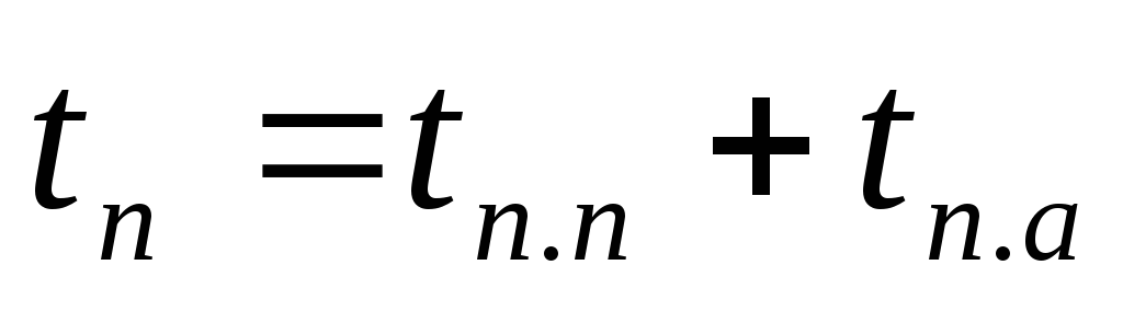
Instant value full current Short circuit for an arbitrary point in time:
Where 
 - aperiodic component of the short-circuit current at the moment of time
  ;
; - angular frequency of alternating current;
  - phase angle of the source voltage at the moment of time ;
 - current shift angle in the short circuit relative to the source voltage; - time constant of the short circuit;
  - inductance, inductive and active resistance of the short circuit circuit.
Periodic component  short circuit current (Fig. 1) is the same for all three phases and is determined for any moment of time by the value of the ordinate of the envelope divided by
  . Aperiodic component
  short circuit current is different for all three phases (see Fig. 2) and varies depending on the moment of occurrence of short circuit.

Rice. 3. Change in time of the periodic component of the short circuit current:
a) when powered by generators without ATS; b) when powered by generators with ATS; c) when powered by the power system.
The amplitude of the periodic component changes in the transient process in accordance with the change source emf Short circuit (Fig. 3). With a source power commensurate with the power of the element where the short circuit is considered, as well as the absence of AVR generators, the EMF of the source decreases from the initial value  to steady state
  , as a result of which the amplitude of the periodic component varies from
  (supertransient short-circuit current) up to
  (sustained short circuit) (Fig. 3a).
In the presence of AVR generators, the periodic component of the short circuit current changes, as shown in fig. 3b. The decrease in the periodic component in the initial period of the short circuit is explained by the inertia of the action of the ARV device, which begins to work through 0.08-0.3 s after the onset of the short circuit. With an increase in the excitation current of the generator, its EMF increases and, accordingly, the periodic component of the short-circuit current up to a steady value.
If the power of the source is significantly greater than the power of the element where the short circuit is considered, which corresponds to a source of unlimited power, for which the internal resistance is zero, then the EMF of the source is constant. Therefore, the periodic component of the short-circuit current is unchanged during the transient process (Fig. 3, c), i.e.
Aperiodic component of short-circuit current  is different in all phases and may vary depending on the moment of occurrence of the short circuit and the previous mode (within the period). The decay rate of the aperiodic current component depends on the ratio between the active and inductive resistance of the short circuit circuit, i.e. from constant
  : the greater the active resistance of the circuit, the more intense the attenuation. The aperiodic component of the short circuit current noticeably manifests itself only in the first 0.1-0.2 s after the onset of the short circuit. Usually is determined by the largest possible instantaneous value, which (in circuits with predominant inductive resistance
  ) takes place at the moment when the source voltage passes through the zero value (
  ) and no load current. Wherein
  .In this case, the total short-circuit current has the greatest value. These conditions are calculated when determining short-circuit currents.
Maximum instantaneous current Short circuit takes place after about half a period, i.e. 0.01 s after the occurrence of a short circuit. The highest possible instantaneous short circuit current is called shock current  (Fig. 3). It is determined for the moment
  With:
With:
Where  - shock coefficient, depending on the time constant of the short circuit.
The effective value of the total short-circuit current for an arbitrary moment of time is determined from the expression:
 (3.4)
(3.4)
Where  - effective value of the periodic component of the short circuit current;
  - effective value of the aperiodic component equal to
 (3.5)
(3.5)
The largest effective value of the shock current for the first period from the beginning of the short circuit process:
 (3.6)
(3.6)
Short-circuit power for an arbitrary moment of time:
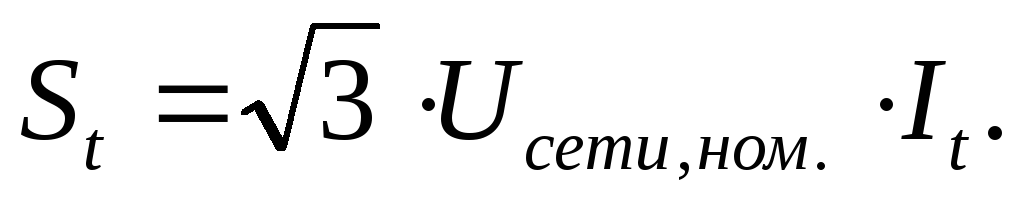 (3.7)
(3.7)
Short circuit power supplies. When calculating short circuit currents, it is assumed that the power sources of the short circuit are turbo and hydro generators, synchronous compensators and motors, and asynchronous motors. The influence of asynchronous motors is taken into account only at the initial moment of time and in those cases when they are connected directly to the place of short circuit.
Determined quantities. When calculating short-circuit currents, the following quantities are determined:
 - the initial value of the periodic component of the short circuit current (the initial value of the supertransient short circuit current);
 - shock short-circuit current, necessary for checking electrical devices, tires and insulators for electrodynamic stability;
 - the largest effective value of the shock short-circuit current, necessary for checking electrical apparatus for stability during the first period of the short-circuit process;
 - meaning For
 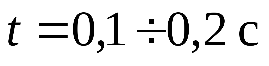 , necessary to check the circuit breakers for the current they turn off;
 - the effective value of the steady-state short-circuit current, according to which electrical devices, tires, bushings and cables are checked for thermal stability;
 - short circuit power for time ;determined to test circuit breakers according to the maximum permissible disconnected power. For high-speed circuit breakers, this time can be reduced to 0.08 s.
Assumptions and design conditions. To facilitate the calculation of short-circuit currents, a number of assumptions are made:
1) EMF of all sources are considered to be in phase;
2) EMF sources, significantly remote from the place of short circuit (  ), are considered unchanged;
3) do not take into account transverse capacitive short circuit circuits (except for overhead lines 330 kV above and cable lines 110 kV above) and magnetizing currents of transformers;
4) the active resistance of the short circuit circuit is taken into account only with the ratio  ,
Where
,
Where  And
And  - equivalent active and reactive resistances of a short-circuited circuit;
5) in some cases, the influence of loads is not taken into account (or taken into account approximately), in particular, the influence of small asynchronous and synchronous motors.
In accordance with the purpose of determining short circuit currents, design conditions are established, which include drawing up a design scheme, determining the short circuit mode, short circuit type, location of short circuit points and estimated short circuit time.
When determining the short circuit mode, depending on the purpose of the calculation, the possible maximum and minimum levels of short circuit currents are determined. So, for example, checking electrical equipment for the electrodynamic and thermal effects of short-circuit currents is carried out according to the most difficult mode - the maximum, when the highest short-circuit current flows through the element under test. On the contrary, according to the minimum mode corresponding to the smallest short-circuit current , calculate and check the operability of relay protection and automation devices.
Selecting the type of short circuit determined by the purpose of calculating short-circuit currents. To determine the electrodynamic resistance of devices and hard tires, a three-phase short circuit is taken as the calculated one; to determine the thermal resistance of devices, conductors - a three-phase or two-phase short circuit, depending on the current. Checking the breaking and making abilities of the devices is carried out according to a three-phase or according to single-phase current Short circuit to earth (in networks with high earth fault currents) depending on its value.
The choice of the type of short circuit in the calculations of relay protection is determined by its functional purpose and can be three-, two-, single-phase and two-phase short circuit to ground.
Locations of short circuit points are chosen in such a way that during a short circuit the electrical equipment under test, the conductors are in the most unfavorable conditions. For example, to select switching equipment, it is necessary to choose the location of the short circuit directly at their output terminals; the selection of the cable line section is made according to the short circuit current at the beginning of the line. The locations of short circuit points in the calculations of relay protection are determined according to its purpose - at the beginning or end of the protected area.
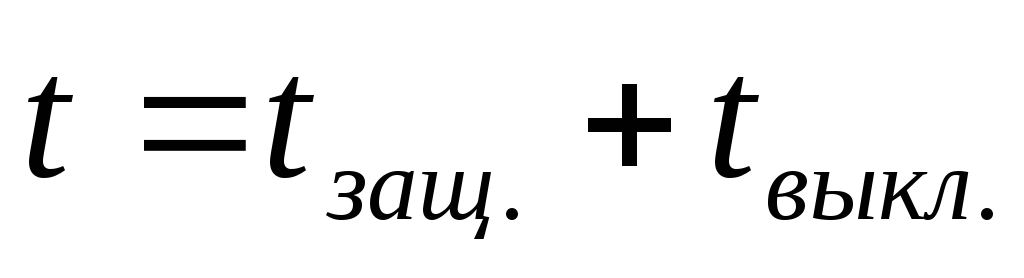
Estimated short circuit time. The actual time during which a short circuit occurs is determined by the duration of the protection and disconnecting equipment,
 . (3.8)
The calculations use the reduced (fictitious) time - the period of time during which the steady-state short-circuit current releases the same amount of heat that the actually passing short-circuit current should release during the actual short-circuit time.
The reduced time corresponding to the total short-circuit current,
 . (3.9)
Where  - reduced time for the periodic component of the short circuit current;
 - the reduced time for the aperiodic component of the short circuit current.
With real time  with the reduced time for the periodic component of the short circuit current is determined by nomograms.
With real time  With
With  , Where
  - the value of the given time for
  With.
With.
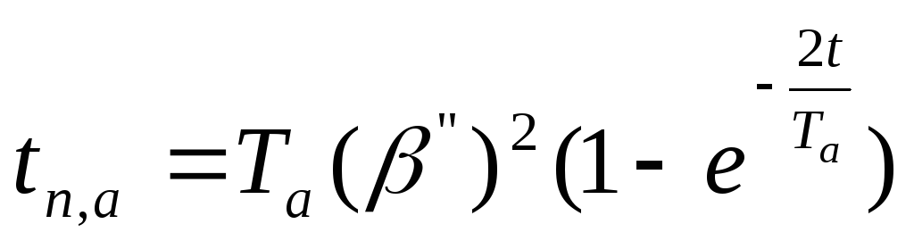
Determination of the reduced time for the aperiodic component , and is produced at  according to the formula:
 , (3.10)
Where  - the ratio of the initial supertransient current to the current established at the fault location (
  ).
).
At  - according to the formula:
 . (3.11)
With real time more than 1 sec. or  the reduced time of the aperiodic component of the short-circuit current ( ) can be neglected.
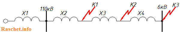
Required to complete calculation of three-phase short-circuit current (TKZ) on the buses of the designed ZRU-6 kV 110/6 kV substation "GPP-3". This substation is powered by two 110 kV overhead lines from the 110 kV GPP-2 substation. ZRU-6 kV "P4SR" receives power from two power transformers TDN-16000/110-U1, which work separately. When one of the inputs is disconnected, it is possible to supply power to the de-energized busbar section by means of a sectional switch in automatic mode (ATS).
Figure 1 shows design scheme networks
Since the chain from I s.sh. "GPP-2" to I s.sh. "GPP-3" is identical to chain II s.sh. from "GPP-2" to II s.sh. "GPP-3" calculation is carried out only for the first chain.
The equivalent circuit for calculating short-circuit currents is shown in Figure 2.
The calculation will be made in named units.
2. Initial data for calculation
- 1. System data: Ikz=22 kA;
- 2. Data for overhead lines - 2xAS-240/32 (Data are given for one AC-240/32 circuit, RD 153-34.0-20.527-98, Appendix 9):
- 2.1 Direct sequence inductive reactance - Х1ud=0.405 (Ohm/km);
- 2.2 Capacitive conductivity - wsp=2.81x10⁻⁶ (S/km);
- 2.3 Active resistance at +20 C per 100 km of the line - R=R20C=0.12 (Ohm/km).
- 3. Transformer data (taken from GOST 12965-85):
- 3.1 TDN-16000/110-U1, Uin=115 kV, Unn=6.3 kV, OLTC ±9*1.78, Uk.in-nn=10.5%;
- 4. Data of the flexible conductor: 3хАС-240/32, l=20 m. (To simplify the calculation, the resistance of the flexible conductor is not taken into account.)
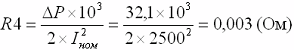
- 5. Data of the current limiting reactor - RBSDG-10-2x2500-0.2 (taken from GOST 14794-79):
- 5.1 Rated current reactor - Inom. = 2500 A;
- 5.2 Nominal power losses per reactor phase - ∆P= 32.1 kW;
- 5.3 Inductive resistance - Х4=0.2 Ohm.
3. Calculation of element resistances
3.1 System resistance (for voltage 115 kV):
![]()
3.2 Resistance overhead line(for voltage 115 kV):
Where:
n - Number of wires in one overhead line VL-110 kV;
3.3 Total resistance to the transformer (for voltage 115 kV):
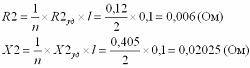
X1.2 \u003d X1 + X2 \u003d 3.018 + 0.02025 \u003d 3.038 (Ohm)
R1.2=R2=0.006 (Ohm)
3.4 Transformer resistance:
3.4.1 Active resistance of the transformer (OLTC is in the middle position):
3.4.2 Active resistance of the transformer (OLTC is in the extreme "minus" position):
3.4.3 Active resistance of the transformer (OLTC is in the extreme "positive" position):
Minimum inductive resistance of the transformer (OLTC is in the extreme "minus" position)

The maximum inductive resistance of the transformer (OLTC is in the extreme "positive" position)

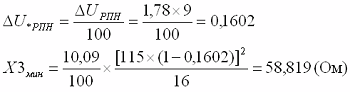
The value included in the formula above is the voltage corresponding to the extreme positive position of the on-load tap-changer, and it is equal to Umax.VN = 115 * (1 + 0.1602) = 133.423 kV, which exceeds the highest operating voltage of electrical equipment equal to 126 kV (GOST 721-77 " Power supply systems, networks, sources, converters and receivers electrical energy. Rated voltages over 1000 V"). The voltage UmaxVN corresponds to Uk%max=10.81 (GOST 12965-85).
If Umax.VN, it turns out more than the maximum allowable for this network (Table 5.1), then Umax.VN should be taken according to this table. The value Uk% corresponding to this new maximum value Umax.VN is determined either empirically or found from the applications of GOST 12965-85.

3.4.5 Resistance of the current-limiting reactor (at a voltage of 6.3 kV):
4. Calculation of three-phase short-circuit currents at point K1
4.1 Total inductive reactance:
X∑=X1.2=X1+X2=3.018+0.02025=3.038 (Ohm)
4.2 Total active resistance:
R∑=R1.2=0.006 (Ohm)
4.3 Total impedance:
4.4 Three-phase short circuit current:

4.5 Surge short-circuit current:

5. Calculation of three-phase short-circuit currents at point K2
6.1.1 The value of the total resistance at point K2, we lead to a network voltage of 6.3 kV:
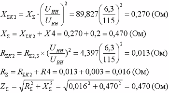
6.1.2 The current at the place of a short circuit, reduced to an effective voltage of 6.3 kV, is equal to:
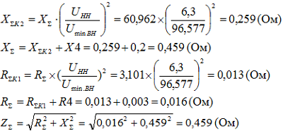
6.1.3 Surge short-circuit current:

6.2 Resistance on the busbars of the ZRU 6 kV with the on-load tap-changer of the T3 transformer set to the minus position
6.2.1 The value of the total resistance at point K2 is reduced to a network voltage of 6.3 kV:
6.2.2 The current in the place of a short circuit, reduced to an effective voltage of 6.3 kV, is equal to:

6.2.3 Surge short-circuit current:
6.3 Resistance on the busbars of the ZRU 6 kV with the on-load tap-changer of the T3 transformer installed in the positive position
6.3.1 The value of the total resistance at point K2, we lead to a network voltage of 6.3 kV:

6.3.2 The current at the location of the short circuit, reduced to an effective voltage of 6.3 kV, is equal to:

6.3.3 Surge short-circuit current:
The results of the calculations are entered in table РР1.3
Table РР1.3 - Calculation data for three-phase short-circuit currents
| Transformer tap position | Short circuit currents | Short circuit point | ||
|---|---|---|---|---|
| K1 | K2 | K3 | ||
| Tap changer in middle position | Short circuit current, kA | 21,855 | 13,471 | 7,739 |
| Surge current short circuit, kA | 35,549 | 35,549 | 20,849 | |
| Short circuit current, kA | - | 13,95 | 7,924 | |
| Surge current short circuit, kA | - | 36,6 | 21,325 | |
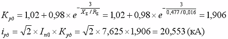
| Tap changer in positive position | Short circuit current, kA | - | 13,12 | 7,625 |
| Surge current short circuit, kA | - | 34,59 | 20,553 | |
7. Calculation of short circuit current made in Excel
If you perform this calculation using a piece of paper and a calculator, it takes a lot of time, besides, you can make a mistake and the whole calculation will go down the drain, and if the initial data is constantly changing, this all leads to an increase in design time and unnecessary waste of nerves.
Therefore, I decided to perform this calculation using an Excel spreadsheet, so as not to waste my time on recalculating the TKZ and protect myself from unnecessary errors, with its help you can quickly recalculate the short circuit currents, changing only the initial data.
I hope that this program will help you and you will spend less time designing your facility.
8. References
- 1. Guidelines for the calculation of short-circuit currents and the choice of electrical equipment.
RD 153-34.0-20.527-98. 1998 - 2. How to calculate the short circuit current. E. N. Belyaev. 1983
- 3. Calculation of short circuit currents in power networks 0.4-35 kV, Golubev M.L. 1980
- 4. Calculation of short circuit currents for relay protection. I.L. Nebrat. 1998
- 5. Rules for the installation of electrical installations (PUE). Seventh edition. 2008
Hello dear friends! In this article, you will learn what short circuit current is, its causes and how to calculate it. A short circuit occurs when current-carrying parts of different potentials or phases are connected to each other. A short circuit can also form on the equipment case that is connected to the ground. This phenomenon is also typical for electrical networks and electrical receivers.
Causes and effects of short circuit current
The causes of a short circuit can be very different. This is facilitated by wet or aggressive environment, in which the insulation resistance deteriorates significantly. A closure can result mechanical influences or human error during repairs and maintenance. The essence of the phenomenon lies in its name and is a shortening of the path along which the current passes. As a result, current flows past the resistive load. At the same time, it increases to unacceptable limits if the protective shutdown does not work.
Short-circuit currents have an electrodynamic and thermal effect on equipment and electrical installations, which ultimately leads to their significant deformation and overheating. In this regard, it is necessary to pre-calculate the short-circuit currents.
How to calculate short circuit current at home
Knowledge of the magnitude of the short circuit current is essential to ensure fire safety. Obviously, if the measured short circuit current is less than the set current maximum protection circuit breaker or 4 times the fuse current rating, then the response time (fusible link burnout) will be longer, and this, in turn, can lead to excessive heating of the wires and their ignition.
How can this current be determined? Exist special techniques and special devices for this. Here we consider the question of how to do this, having only or even a voltmeter. It is obvious that this method has not very high accuracy, but still sufficient to detect the discrepancy between the overcurrent protection and the value of this current.
How to do it at home? It is necessary to take a sufficiently powerful receiver, for example, Electric kettle or iron. It would be nice to have a trio. We connect our consumer and a voltmeter or multimeter to the tee in voltage measurement mode. We write down the steady value of the voltage (U1). We turn off the consumer, and record the voltage without load (U2). Next, we make a calculation. You need to divide the power of your consumer (P) by the difference in the measured voltages.
Ic.c.(1) = Р/(U2 – U1)
Let's count on an example. Kettle 2 kW. The first measurement is 215 V, the second measurement is 230 V. According to the calculation, it turns out 133.3 A. If, for example, there is a VA 47-29 machine with characteristic C, then its setting will be from 80 to 160 Amperes. Therefore, it is possible that this machine will work with a delay. According to the characteristics of the machine, it can be determined that the response time can be up to 5 seconds. Which is basically dangerous.
What to do? It is necessary to increase the magnitude of the short circuit current. You can increase this current by replacing the wires of the supply line with a larger cross section.
Useful short circuit
It would seem that the obvious fact is that a short circuit is an extremely bad, unpleasant and undesirable phenomenon. It may lead to best case to de-energize the facility, turn off emergency protective equipment, and at worst - to burn out the wiring and even fire. Therefore, all efforts must be focused on avoiding this scourge. However, the calculation of short-circuit currents has a very real and practical meaning. A lot has been invented technical means operating in the mode of high current values. An example is the usual welding machine, especially arc, which at the time of operation almost short-circuits the electrode with grounding. Another issue is that these regimes are of a short-term nature, and the power of the transformer makes it possible to withstand these overloads. When welding at the point of contact of the end of the electrode, huge currents pass (they are measured in tens of amperes), as a result of which enough heat is released to locally melt the metal and create a strong seam.