By the amount of torque asynchronous motor The phase shift between current I 2 and e has a great influence. d.s. E 2S rotor.
Let us consider the case when the inductance of the rotor winding is small and therefore the phase shift can be neglected (Fig. 223, a).
The rotating magnetic field of the stator is here replaced by the field of the poles N and S, rotating, suppose, in a clockwise direction. Using the rule right hand, determine the direction of e. d.s. and currents in the rotor winding. The rotor currents, interacting with the rotating magnetic field, create a torque. The directions of forces acting on current-carrying conductors are determined by the left-hand rule. As can be seen from the drawing, the rotor under the influence of forces will rotate in the same direction as the rotating field itself, i.e. clockwise.
Let's consider the second case, when the inductance of the rotor winding is large. In this case, the phase shift between the rotor current I 2 and e. d.s. the E 2S rotor will also be large. In fig. 223, b, the magnetic field of the stator of an asynchronous motor is still shown in the form of poles N and S rotating clockwise. The direction of the e.g. induced in the rotor winding. d.s. remains the same as in Fig. 223, a, but due to the phase lag of the current, the axis magnetic field The rotor will no longer coincide with the neutral field line of the stator, but will shift by a certain angle against the rotation of the magnetic field. This will lead to the fact that, along with the formation of a torque directed in one direction, some conductors will create a counter torque.
From this it can be seen that the total torque of the motor with a phase shift between current and e. d.s. the rotor is smaller than for the case when I 2 and E 2S are in phase. It can be proven that the torque of an asynchronous motor is determined only by the active component of the rotor current, i.e., the current I 2 cos and that it can be calculated using the formula:
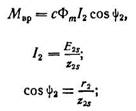
Ф m - magnetic flux of the stator (and also approximately equal to the resulting magnetic flux of the asynchronous motor);
Phase shift angle between e. d.s. and winding phase current
C is a constant coefficient.
After substitution:
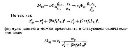
From the last expression it is clear that the torque of an asynchronous motor depends on slip.
In fig. 224 shows curve A of the dependence of engine torque on slip. It is clear from the curve that at the moment of starting, when s=l and n = 0, the engine torque is small. This is explained by the fact that at the moment of starting the frequency of the current in the rotor winding is the highest and the inductive reactance of the winding is high. As a result, cos has a small value (by
|
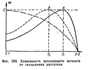
row 0.1-0.2). Therefore, despite the large size starting current, the starting torque will be small.
At some slip S 1, the engine torque will have a maximum value. With a further decrease in slip or, in other words, with a further increase in the engine rotation speed, its torque will quickly decrease.
When sliding s = 0, the rotational torque of the engine will also be zero.
It should be noted that an asynchronous motor practically cannot have zero slip. This is only possible if the rotor is provided with external torque in the direction of rotation of the stator field.
The starting torque can be increased if, at the moment of starting, the phase shift between the current and the e is reduced. d.s. rotor. From the formula
It can be seen that if, with a constant inductive resistance of the rotor winding, the active resistance is increased, then the angle itself will decrease, which will lead to the fact that the engine torque will become greater. This is used in practice to increase the starting torque of the engine. At the moment of starting, an active resistance (starting rheostat) is introduced into the rotor circuit, which is then removed as soon as the engine increases speed.
An increase in starting torque leads to the fact that the maximum engine torque is obtained with greater slip (point S 2 of curve B in Fig. 224). By increasing the active resistance of the rotor circuit at start-up, it is possible to ensure that the maximum torque will be at the moment of start-up (s = 1 curve C).
The torque of an asynchronous motor is proportional to the square of the voltage, so even a small decrease in voltage is accompanied by a sharp decrease in torque.
Power P 1 supplied to the stator winding of an asynchronous motor is equal to:
![]()
where m 1 is the number of phases.
The motor stator has the following energy losses:
1) in the stator winding R es. =m 1 I 1 2 r 1 ;
2) in stator steel there is hysteresis and eddy currents Р C .
The power supplied to the rotor is the power of the rotating magnetic field, also called electromagnetic power P eM.
Electromagnetic power is equal to the difference between the power supplied to the motor and the losses in the motor stator, i.e.
|
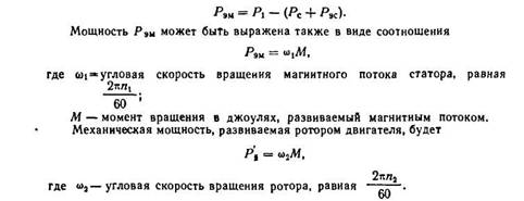
The difference between R eM and represents electrical losses in the rotor winding Р eP, if we neglect losses in the rotor steel due to their insignificance (the frequency of rotor magnetization reversal is usually very small):
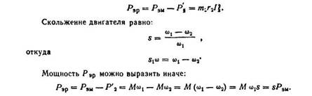
Therefore, the losses in the rotor winding are proportional to the rotor slip.
If from mechanical power developed by the rotor, subtract the mechanical losses P mx caused by friction in the rotor bearings, friction with air, etc., as well as additional losses P D arising under load and caused by stray fields of the rotor, and losses caused by: pulsations of the magnetic field in the stator teeth and the rotor, then it will remain useful power on the motor shaft, which we denote by P 2.
The efficiency of an asynchronous motor can be determined by the formula:
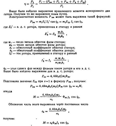
From the last expression it is clear that the rotational torque of an asynchronous motor is proportional to the product of the value of the rotating magnetic flux, the rotor current and the cosine of the angle between e. d.s. rotor and its current,
From the equivalent circuit of an asynchronous motor, the value of the reduced rotor current is obtained, which we present without proof.
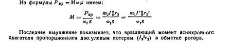
The torque developed by the motor is equal to the electromagnetic power divided by the synchronous rotation speed of the electric drive.
M = P em /ω 0
Electromagnetic power is the power transmitted through the air gap from the stator to the rotor, and it is equal to the losses in the rotor, which are determined by the formula:
P em = m I 2 2 (r 2 '/s)
m – number of phases.
M = M em = (Pm/ω 0) (I 2 ') 2 (r 2 '/s)
An electromechanical characteristic of an asynchronous motor is the dependence of I2’ on slip. But since an asynchronous machine works only as an electric motor, the main characteristic is the mechanical characteristic.
M = Me m = (Pm/ω 0) (I 2 ') 2 (r 2 '/s) - a simplified expression of the mechanical characteristic.
Substituting the current value into this expression, we obtain: M = / [ω 0 [(r 1 + r 2 '/s) 2 + (x 1 + x 2 ') 2 ]]
Instead of ω 0 it is necessary to substitute mechanical speed, as a result of which the number of pole pairs is reduced.
M = / [ω 0 [(r 1 + r 2 ’/s) 2 + (x 1 + x 2 ’) 2 ]] is the equation for the mechanical characteristics of an asynchronous motor.
When the asynchronous motor enters the generator mode, the rotation speed ω > ω 0 and the slip becomes negative (s When the slip changes from 0 to +∞, the mode is called “electromagnetic brake mode”.
Specifying slip values from o to +∞, we obtain the characteristic:
Complete mechanical characteristics of an asynchronous motor.
As can be seen from the mechanical characteristics, it has two extrema: one in the interval of slip change in the area from 0 to +∞, the other in the interval from 0 to -∞. dM/ds=0
M max = / ] + refers to the motor mode. – refers to the generator mode.
M max =M cr M cr – critical moment.
The slip at which the moment reaches its maximum is called critical slip, and it is determined by the formula: s cr = ±
The critical slip has the same meaning in both motor and generator modes.
The value of Mcr can be obtained by substituting the value of the critical slip into the torque formula.
The sliding torque equal to 1 is called the starting torque. The expression for the starting torque can be obtained by substituting 1 into the formula:
M p = / [ω 0 [(r 1 + r 2 ’) 2 + (x 1 + x 2 ’) 2 ]]
Since the denominator in the maximum moment formula is several orders of magnitude greater than U f, it is generally accepted that M cr ≡U f 2.
The critical slip depends on the value of the active resistance of the rotor winding R 2 '. The starting torque, as can be seen from the formula, depends on the active resistance of the rotor r 2 '. This property of the starting torque is used in asynchronous motors with a wound rotor, in which the starting torque is increased by introducing active resistance into the rotor circuit.
7.Idling transformer
Mode idle move transformer is the operating mode when one of the windings of the transformer is powered from a source with alternating voltage and with open circuits of the other windings. A real transformer can have this mode of operation when it is connected to the network, and the load powered from its secondary winding is not yet turned on. Current I 0 passes through the primary winding of the transformer, while at the same time there is no current in the secondary winding, since its circuit is open. Current I 0 passing through the primary winding creates a sinusoidally varying tray F 0 in the magnetic circuit, which, due to magnetic losses, lags in phase with the current by the loss angle δ. 
![]()
The graphically expressed dependence of the electromagnetic torque on slip is called mechanical characteristics asynchronous motor (Fig. 3.3).
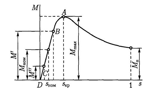
Rice. 3.3. Mechanical characteristics of an asynchronous motor
A simplified formula for calculating the electromagnetic torque of an asynchronous motor (Kloss formula) can be used to construct a mechanical characteristic
In this case, the critical slip is determined by the formula
![]()
where λ m = M max / M nom - overload capacity of the engine.
When calculating the mechanical characteristics, it should be borne in mind that at slip values exceeding the critical value, the accuracy of the calculations sharply decreases. This is explained by a change in the parameters of the equivalent circuit of an asynchronous motor, caused by magnetic saturation of the stator and rotor teeth, and an increase in the frequency of the current in the rotor winding.
The shape of the mechanical characteristics of an asynchronous motor largely depends on the voltage applied to the stator winding U 1 (Fig. 3.4) and the active resistance of the rotor winding r" 2 (Fig. 3.5).
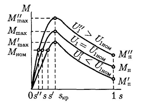
Rice. 3.4. Effect of voltage U 1 on the mechanical characteristics of an asynchronous motor
The data given in catalogs for asynchronous motors usually does not contain information about the parameters of the equivalent circuit, which makes it difficult to use formulas for calculating the electromagnetic torque. Therefore, to calculate the electromagnetic torque, the formula is often used
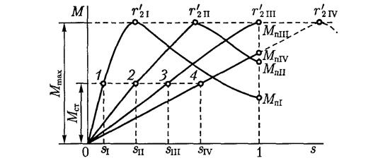
Rice. 3.5. Impact of resistance r" 2 on the mechanical characteristics of an asynchronous motor
The operational properties of an asynchronous motor are determined by its operating characteristics: the dependence of the rotation speed n 2, torque on the shaft M 2 ,efficiency and power factor cosφ 1 from engine payload R 2 .
When calculating parameters to determine performance characteristics a synchronous motors They use either a graphical method, which is based on the construction of a pie chart, or an analytical method.
The basis for performing any of the performance calculation methods is the results of no-load and short-circuit experiments. If the engine is being designed, then this data is obtained during its calculation.
When calculating resistor resistances r add, used in stator or wound rotor circuits to limit the starting current or control the rotation speed, use the principle: for this particular asynchronous motor, slip s proportional to the active resistance of the rotor circuit of this motor. In accordance with this, the equality is true
(r 2 + r ext) /s= r 2 /s nom,
Where r 2- active resistance of the rotor winding itself at operating temperature; s- sliding when a resistor is introduced into the rotor circuit with resistance r ext.
From this expression we obtain a formula for calculating the active resistance of the additional resistor g to6, necessary to obtain a given increased slip s at a given (nominal) load:
r ext = r 2 (s/s nom - 1).
There are two methods for calculating starting rheostats: graphical and analytical.
Graphical method more accurate, but requires the construction of a natural mechanical characteristic and starting diagram of the engine, which is associated with a large amount of graphic work.
Analytical method calculating starting rheostats is simpler, but less accurate. This is due to the fact that the method is based on the assumption that the working section of the natural mechanical characteristic of an asynchronous motor is straight. But when sliding is close to critical, this assumption causes a noticeable error, which is more significant the closer the initial starting moment M 1 to maximum torque M m ah. Therefore, the analytical calculation method is applicable only for values of the initial starting torque M 1 < 0.7· M m ah .
Resistor resistances at the starting rheostat stages:
third r ext3 = r 2 (λ m - 1);
second r ext2 = r ext3 λ m;
first r ext1 = r ext2 λ m,
Where r 2 - active resistance of the phase winding of the rotor of an asynchronous motor,
Where E 2 and I 2nom - catalog data for the selected motor size.
Resistance of the starting rheostat at its stages:
first R PR1 = r ext1 + r ext2 + r ext3 ;
second R PR2 = r ext2 + r ext3
third R PR2 = r ext3 .
To limit the starting current of asynchronous motors with squirrel-cage rotor special circuits for their inclusion are used with elements that limit the starting current. All these methods are based on reducing the voltage supplied to the stator winding. Most Applications received circuits with the inclusion of resistors or chokes in the linear wires of the stator (see Fig. 3.14, b The calculation of the required resistance of these elements for a given decrease in starting current a, relative to its natural value, is carried out using the formulas:
for resistors with active resistance
R n = 
for chokes
X L= 
Impedance motor in short circuit mode Z k, Ohm,
Z k =U 1 /I P
Here X to and r k - inductive and active components of this resistance
R k = Z k cosφ k ; x k =
Reducing artificial starting torque when turning on R or L will be
α m = α 2 i
Table 3.1
Thus, if the value α m is given, which determines the value of the artificial starting torque M" p, then to calculate the corresponding values R p or x L you can use the above formulas by substituting in them instead of α 2 i, value α m.
Electrical resistance The motor windings listed in the catalogs usually correspond to a temperature of +20 °C. But when calculating the characteristics and parameters of motors, the resistance of their windings must be brought to operating temperature. In accordance with the current standard, the operating temperature is taken depending on the heat resistance class electrical insulation applied in the engine: with heat resistance class B, the operating temperature is 75 °C, and with heat resistance classes F and H - 115 °C. Conversion of winding resistance to operating temperature is performed by multiplying the winding resistance at a temperature of 20 °C by the heating coefficient k t:
r= r 20k t.
The values of this coefficient are taken depending on the purpose of the engines and their dimensions (height of the axis of rotation) (Table 3.1).
SYNCHRONOUS MACHINES
BASIC CONCEPTS
A characteristic feature synchronous machines is a rigid connection between the rotor speed n 1 and frequency alternating current in the stator winding f 1:
n 1 = f 1 60/ R.
In other words, the rotating magnetic field of the stator and the rotor of the synchronous machine rotate synchronously, i.e. with the same frequency.
According to their design, synchronous machines are divided into salient-pole and non-salient-pole. In salient-pole synchronous machines, the rotor has salient poles on which the field winding coils, powered by DC. A characteristic feature of such machines is the difference in magnetic resistance along the longitudinal axis (along the axis of the poles) and along the transverse axis (along the axis passing in the interpolar space). Magnetic resistance to stator flux along the longitudinal axis dd much less magnetic resistance to stator flux along the transverse axis qq. In non-salient-pole synchronous machines, the magnetic resistances along the longitudinal and transverse axes are the same, since the air gap of these machines around the perimeter of the stator is the same.
The design of the stator of a synchronous machine is, in principle, no different from the stator of an asynchronous machine. In the stator winding, during operation of the machine, an EMF is induced and currents flow, which create a magnetomotive force (MF), the maximum value of which is
F 1 =0,45m 1 I 1 w 1 k rev1 / R
This MMF creates a rotating magnetic field, and in the air gap δ The machine creates magnetic induction, the distribution graph of which within each pole division m depends on the design of the rotor (Fig. 4.1).
For a salient-pole synchronous machine, the voltage equation is valid:
Ú 1 =Ė 0 + Ė 1 d + Ė 1 q + Ė σ1 – İ 1 r 1
Where Ė 0 - main EMF of a synchronous machine, proportional to the main magnetic flux of the synchronous machine F 0 ; Ė 1 d - EMF of the armature reaction of a synchronous machine along the longitudinal axis, proportional to the MMF of the armature reaction along the longitudinal axis F 1d; Ė σ1 - EMF of the armature reaction along the transverse axis, proportional to the MMF of the armature reaction along the transverse axis F 1 q ; Ė σ1 - leakage emf due to the presence of magnetic leakage flux F 0, the magnitude of this EMF is proportional to the inductive leakage resistance of the stator winding X 1
Ė σ1 = jİ 1 r
İ 1 r 1 - active voltage drop in the stator phase winding; usually this value is neglected when solving problems due to its small value.
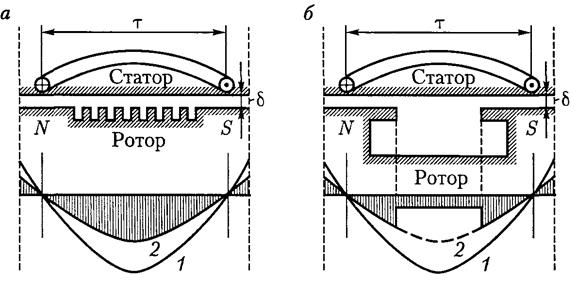
Rice. 4.1. Graphs of magnetic induction distribution along the transverse axis
non-salient pole ( A) and salient pole ( b)synchronous machines:
1 - MDS schedule; 2 - magnetic flux graph
For a non-salient-pole synchronous machine, the voltage equation has the form
Ú 1 =Ė 0 + Ė c – İ 1 r 1
Here
Ė c = Ė 1 + Ė σ1
Where Ė 1 - EMF reaction of the armature of a non-salient-pole synchronous machine. The stress equations considered above correspond to stress vector diagrams. These diagrams have to be constructed to determine either the main emf of the machine E 0, or stator winding voltage U 1. It should be borne in mind that the voltage equations and the corresponding vector diagrams do not take into account the magnetic saturation of the magnetic circuit of a synchronous machine, which, as is known, affects the value of inductive reactances, causing them to decrease. Taking into account this saturation is a difficult task, therefore, when calculating the EMF and voltages of synchronous machines, they usually use practical diagram EMF, which takes into account the state of saturation of the magnetic system caused by the action of the armature reaction when the synchronous machine is loaded. When constructing a practical EMF diagram, the magnetizing force of the armature reaction is not decomposed into longitudinal and transverse components, therefore this diagram can be used both in the calculations of salient-pole and non-salient-pole machines.
When solving problems associated either with synchronous generators connected in parallel with the network, or with synchronous motors, they use angular characteristics synchronous machines, representing the dependence of the electromagnetic torque M on the load angle θ. It should be remembered that in salient-pole synchronous machines two points operate: the main M basic and reactive M p, and in non-salient pole machines - only the main point:
![]()
Load angle θ nom corresponds to rated torque M nom. The maximum torque of a synchronous machine determines the overload capacity of the synchronous machine, which is important both for synchronous generators operating in parallel with the network and for synchronous motors. In non-salient-pole synchronous machines, the maximum torque corresponds to the load angle θ = 90°, in salient-pole machines θ cr< 90° и обычно составляет 60 - 80° в зависимости от соотношения основного и реактивного electromagnetic moments this car.
To calculate the critical load angle, which determines the overload capacity of salient-pole synchronous machines, you can use the expression.