When starting, i.e. when starting off and accelerating, the torque developed by the motor must exceed the moment of resistance of the load, otherwise the motor will not be able to accelerate. At the initial moment of starting, when the motor speed is zero, and the slip is one, the EMF in the rotor winding is maximum (see 2.37), and the starting current in the stator winding I 2, in accordance with (2.40), significantly exceeds the rated operating current. Accordingly, the current in the stator winding also increases, that is, the current consumed by the motor from the supply network. Multiplicity of starting current y p \u003d I P / I NOM for motors with squirrel-cage rotor reaches 5 - 7. As the motor accelerates, the slip decreases, which leads to a decrease in the EMF and current in the rotor winding. Accordingly, the current in the stator winding also decreases.
A large starting current may be unacceptable, both for the motor itself and for the network supplying the motor. If starts are carried out frequently, then a large starting current leads to an increase in the temperature of the motor windings, which can lead to premature aging its isolation. If, after applying voltage to the motor, it does not start for any reason, the motor must be switched off immediately, automatic device overcurrent protection, or manually. In the supply network, with a large current strength, the voltage decreases, which affects the operation of other consumers connected to the network. Therefore, direct starting of the engine by direct connection to the mains is allowed only if the engine power is much less than the power for which the power supply is designed.
For motors with a phase rotor, the reduction in starting current is achieved by including a three-phase starting rheostat in the rotor circuit. The active resistances included in the circuit of each phase of the rotor provide a decrease in the current in the rotor winding, and hence in the stator winding. At the same time, an increase in active resistance in the rotor circuit provides an increase in the power factor cosψ 2, and obtaining a sufficiently large starting torque with reduced starting current. As the engine speed increases, the resistance of the starting rheostat gradually or stepwise decreases to zero.
It is possible to reduce the starting current of a squirrel-cage induction motor by starting at a reduced supply voltage. It is also possible to turn on for the time of starting according to the star scheme, the stator winding designed for delta connection. However, these methods significantly reduce torque and are only applicable to no-load or light-load starting. Reduce starting current while maintaining high torque by starting at a reduced supply voltage frequency.
For mechanisms with difficult conditions start, in which it is desirable to use an asynchronous motor with a squirrel-cage rotor, it is advisable to use motors with improved starting properties: with a large starting torque and less than that of motors general purpose, starting current. These are engines with a two-cell and deep-slot rotor. The shape of the grooves and active conductors of the armature winding of a two-cell and deep-groove rotor is shown in fig. 2.30
The rotor of a two-cell motor has two short-circuited windings: external 1 (Fig. 2.30a.), or starting, made with rods with a small cross section of a material with low electrical conductivity (brass, bronze) and internal 2, or working - made with rods with a large cross section from a material with high electrical conductivity (copper). At the beginning of the motor start (at n = 0, s = 1), the frequency of the current in the rotor is equal to the frequency of the network. In this case, the inductive resistances of the cells are large compared to the active ones (X L = 2πfL). The inductive resistance of the lower, working, cage, deeply immersed in the body of the rotor and coupled with a large leakage flux, is especially high (shown by dotted lines in Fig. 2.30). The current passes mainly through the upper cage with a large active resistance, due to which the starting current decreases and the starting torque increases. As the engine accelerates, the rotor current frequency decreases tenfold, since the slip decreases from one to hundredths of it. Consequently, the inductive resistance of the rotor, proportional to the frequency, decreases and becomes insignificant for both the starting and working windings. In this case, the rotor current, which is distributed between the cells in inverse proportion to their resistances, begins to flow mainly in the working winding with low active resistance. Thus, the process of starting a two-cell engine is similar to the process of a rheostatic start of an engine with a phase rotor.
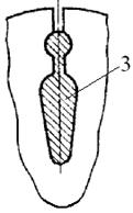
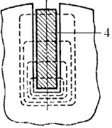
Figure 2.30 - Forms of grooves of a two-cell and deep-slot rotor
There are other rotor designs with a double cage, for example, with figured grooves 3 filled with aluminum (Fig. 2.30b). Here, the increased active resistance of the cell during start-up is provided only by displacing the current into the upper parts of the conductors, since the material of both cells is the same. This design is simpler and cheaper, but the starting characteristics of the engine are somewhat worse.
Similarly, the displacement of current in upper part conductor at start-up, when the current frequency in the rotor is high, is provided in a deep-groove rotor (Fig. 2.30c), in which conductor 4, usually copper, is very elongated in height. Displacement of the current into the upper part of the conductor is equivalent to a decrease in its cross section and provides an increase in the active resistance of the rotor during start-up and a decrease in the starting current.
Everyone who has encountered the starting of electric motors is familiar with the expression, the starting current of an electric motor. When starting, the starting current of the electric motor, depending on the power and rated speed, can be from 2 to 8 times the value.
All this negatively affects the work of other consumers working in the same line with this equipment. With such launches, which are characterized high level consumption reactive power behind short period time, other electric motors and those consumers for which the voltage stability indicator is a priority are in an uncomfortable state. This situation leads to unpredictable consequences in the operation of this electrical equipment. After all, each such start-up sharply lowers the voltage of the supply network. In order to reduce negative impacts There are several such processes traditional methods in order to reduce
1. The start of the electric motor is carried out after removing the mechanical loads on the drive shaft of the electric motor, the so-called idle start. Then the electric motor is loaded, gradually bringing it to the operating mode. This method is applicable to the operation of pumps and ventilation systems, where it is possible to regulate the load on the electric motor using consumable and suction locking elements. This reduces the amount of reactive power, and hence motor starting current.
2. Turning on the electric motor according to the star → delta scheme. This method is applicable for certain condition. The motor must have a winding for the required voltage range. For our industrial network this range is 380/660V. If this condition is met, the motor is started in a soft mode, in which the starting currents do not exceed the rated currents by more than 2 times.
3. Autotransformer start. Starting in this way is somewhat reminiscent of the previous action, only the supply of voltage to the starting electric motor is carried out by smoothly applying voltage through an autotransformer.
This type of launch is practically not used due to its high cost and significant dimensions of ballasts.
4. Use of starting resistors or reactors to limit starting currents. Where a current exceeding a certain predetermined value is released in the form of thermal energy on quenching resistors.
5. Frequency regulators. A new direction in launch solutions and the ability to reduce . This method is being implemented everywhere where it is necessary and not necessary. This starting method does not require significant financial investments, if it concerns electric motors of small power 10–30 kW. When equipping electric motors of higher power with such devices, their cost can significantly exceed the cost of the electric motor itself.
6.Soft start device based on modern solid-state electronic elements - thyristors, such starting devices are controlled by the phase control method. But this method has one significant drawback; in networks of insufficient power, voltage dips cannot be compensated. Such a device is subject to critical operating modes in this mode and its failure is a matter of time.
In solving this problem, the consumer must find an acceptable solution for the efficient and safe start of powerful electric motors and reduce
No related posts
In most cases, asynchronous motors are switched on by direct connection to the network. In the stator circuit of the motor, the contacts of the electromagnetic starter are closed, the windings are connected to the linear voltage of the network, a rotating electromagnetic field appears, and the drive starts to work.
Of course, in this case, an inrush current occurs, exceeding the nominal value by five to seven times. And the duration of this throw depends on the duration of the start, that is, on the engine power. The larger the motor, the longer it takes to accelerate and the longer the effect of the increased current on the supply network and the stator winding will be.
For "weak" asynchronous electric drives with a power of not more than 3 kW, these disadvantages of direct connection to the network are not critical. Of course, the inrush current that takes place cannot be neglected, but even household network alternating current usually has some power reserve to withstand momentary overload.
As for the drive motor itself, in the absence of voltage drops, it will always start without any consequences for itself. That's why, direct connection in the network is often used for asynchronous drives of small pumping and fan installations, circular saws, emery, machine tools.
The start of these drives occurs in relatively favorable conditions, and the engines are designed for permanent job when connected stator windings into a "star" and a linear voltage of 380 volts (nominal voltage 380/220 volts).
But when the engine power is estimated at ten, 15 or more kilowatts, direct connection to the network becomes simply unacceptable. Then the inrush current surges must be limited, as they create an unnecessary load on the network and can cause a “drawdown” of the voltage.
The most popular way to limit the inrush current of an induction drive is undervoltage starting. For 660/380 volt motors, such a start can technically be implemented by switching the windings from star to delta. In the "star" the motor consumes less current, and the load on the network is reduced.
Switching to the "triangle" a few seconds after the start can be arranged using a time relay, or by controlling the current in the stator circuit. However, there is one problem - when the supply voltage decreases, the motor torque on the shaft also decreases.
Moreover, if the voltage was reduced by half, then the moment decreases by four times - the dependence is quadratic. And this despite the fact that the starting moment induction motors already limited due to the peculiarities of the asynchronous mechanical characteristic.
Therefore, voltage reduction and switching from "star" to "delta" is used only in electric drives that have the technological ability to start in the absence of a load on the shaft. This is relevant for driving engines of converter units, for drives of powerful multi-saw machines and similar drives.
Starting at reduced voltage is not at all suitable, for example, for a belt conveyor drive, which almost always has to be started in a loaded state. For such drives, a rheostatic start is used, which also allows you to limit the starting current of the motor, but without reducing the torque.
For rheostatic starting, motors with a phase rotor are used, which allows you to include additional resistances in your circuit. Resistances can also be output in stages, while the start will be smoother. Rheostat control is often used to change the speed of the drive during operation.
But the most efficient for an asynchronous drive is to start using frequency converter(PC). By changing the frequency and magnitude of the supply voltage, the converter allows the asynchronous motor to start and run with optimal performance in any drive. In this case, current surges are completely excluded, and the torque reaches the maximum possible values.
Calculation of the power system of any submersible pump must include a correction for its inrush current. According to various documentation found on the net, starting current is taken equal to the operating current of the pump, increased by 3-7 times. There is even a mention of a 9-fold multiplier.
Let's see what the magnitude of the starting current depends on. First of all, of course - from the engine model. The more and more powerful engine, the stronger the inertial moment of its rotor, the more energy is needed to spin it. Therefore, the calculated current multiplier at start-up increases from 3 for half-kilowatt motors to 4 for motors with a power of two kilowatts.
at the time of its launch, it also plays an important role - a freely rotating rotor in the pump will provide less current at start-up than loaded with a multi-meter column of water in the water main.Multiplier table for starting currents of Grundfos SP pumps
The table shows the dependence of the operating current In in amperes and the multiplier for the starting current Ist / In on the power P2 for single-phase and three-phase motors Grundfos SP range. The actual acceleration time is 0.1 seconds.
| P2 kWt | In, A (1x230) | Ist/In (1x230) | In, A (3x400) | Ist/In (3x400) |
| 0.37 | 3.95 | 3.4 | 1.40 | 3.7 |
| 0.55 | 5.80 | 3.5 | 2.20 | 3.5 |
| 0.75 | 7.45 | 3.6 | 2.30 | 4.7 |
| 1.1 | 7.30 | 4.3 | 3.40 | 4.6 |
| 1.5 | 10.2 | 3.9 | 4.20 | 5.0 |
| 2.2 | 14.0 | 4.4 | 5.50 | 4,7 |
Do not be surprised by the discrepancy between the current consumed by the motor in the table and the power in kilowatts - manufacturers of motors for pumps give the power on the motor shaft in the characteristics, and it depends on the efficiency and is less than the power consumed by it electrical power. And the current is given for the motor at full load.
The limitation on the number of pump starts per hour is due to the large heat generation on the motor windings by the starting current. With too frequent switching on, the windings will overheat.
Too much overheating of the windings leads to a loss of the insulating properties of the varnish that covers the turns, an interturn circuit and failure of the pump motor.
Side effects
During heavy engine operation ( high altitude pressure, clogged inlet filter, deposits in the water supply, wear of the pump components) the magnitude and duration of the starting current can be significantly higher than calculated.
During the inrush current, the voltage drop across the pump power cable increases. IES 3-64 rules allow a drop of no more than 4% of the input voltage.
Starting current fight
Direct-on-line starting is the simplest and cheapest solution, but the high starting current limits its use. To get rid of this disadvantage, other methods are used:
1. Soft starter- this is the most effective method reducing the starting current. One of its main disadvantages is the high cost of the converter.
For Grundfos pumps SQ and SQE have no limits on the number of starts per hour because the frequency converter and soft starter are already built into the motor housing.
Simplified, the work of the soft starter consists in a smooth increase in voltage on the motor for 2 seconds. During this time, the rotor has time to spin up to the required speed, without increasing the load on the network.
2. Consistent connection via transformer with multiple windings. For pumps, 1-2 sections are usually used, which limit the current when turned on, and as the pump speeds up, they are taken out of the circuit in turn. The initial voltage drop occurs up to a maximum of 50% of the supply voltage.
3. For three-phase pump motors with a power of more than 3 kilowatts, you can apply a start-up scheme with switching from star to delta. At the moment of starting, the motor is switched on according to the "star" scheme, which gives a decrease in the starting current by 3 times, and only after the motor has accelerated, the connection is switched over according to the "triangle" scheme.
Limitation of starting currents asynchronous
When an asynchronous motor is connected to the network, a large starting current occurs, which exceeds the rated current in 5…
7 times and causing a significant voltage drop in the line, which can lead to a stop of a number of running motors. Under the action of the starting current, dynamic forces arise in the motor that damage and destroy the winding, are loaded power transformers and the line, which also leads to additional power losses - the limitation of starting currents is especially important for agricultural installations due to the remoteness of electric motors from power sources and the commensurability of the power of transformers and the starting power of electric motors. Frequent starts heat up the motor windings.
There are several ways to limit starting currents: by including additional active or inductive resistance in the stator circuit; inclusion of additional active or inductive resistance in the rotor circuit; switching the stator winding for the start-up period from the "triangle" to the "star"; voltage drop across the stator. Schemes for reducing starting currents by switching windings from "star" to "triangle" (Fig. 4.21) can be recommended for electric motors whose phase windings are designed for line voltage. This applies to electric drives of press granulators, powerful crushers, etc.). In a network with a voltage of 380 V, it is necessary to use motors designed for a voltage of 660/380 V. With a mains voltage of 380 Vu, the voltage of the motor must be 380/220 V.
Consider the ratio of the starting currents of the motor when connected to the "star":
(4.73)
Where - impedance stator windings when turned on. 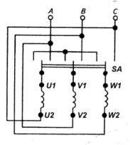
Rice. 4.21. Asynchronous stator winding switching circuit
motor from star to delta.
Starting currents motor when the windings are turned into a "triangle": ![]()
Current ratio:  (4.74)
Thus, when the motor windings are turned on in a “star”, the phase current decreases by a factor, and the linear current by a factor of three. When the phase voltage drops by a factor, the motor torque decreases by a factor of three.
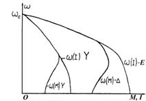
Fig.4.22. Characteristics of an asynchronous motor at
switching the stator windings from star to delta.
Mechanical and electromechanical characteristics when starting the engine in this way are shown in Fig. 4.22. The starting currents of induction motors can be limited by lowering the stator voltage.
Starting current of an asynchronous motor at rated voltage power is equal to:
where is the resistance of the motor phase at the moment of switching on.
To reduce the starting current by a factor, the voltage on the stator of an induction motor must be reduced by the same number of times.
(4.75)
A decrease in the voltage on the stator causes a decrease in the starting torque of the motor in or (1 -. Figure 4.23 shows the mechanical and electromechanical characteristics of an asynchronous motor with a two-fold decrease in starting current. A significant decrease in starting torques allows you to use this way mainly when starting engines on Idling with a relatively small starting moment.

Fig.4.23. Characteristics of an induction motor when stepping down
voltage.
In calculations, when choosing a motor, it is mandatory to check for the possibility of starting with a decrease in voltage: .
You can limit the starting currents of asynchronous motors by including additional active or inductive resistance in the stator circuit.
The calculation of the value of additional active or inductive resistance begins with the choice of the required starting current and the determination of the reduction ratio of this current:
,
where is the starting current of the motor in the absence of resistance in
stator circuits,=
nominal phase voltage networks; stator phase winding resistance; - starting current with the introduction of additional resistance in the stator circuit,  - impedance of the stator winding circuit upon introduction or
Let us substitute the values of the currents and
a =  .
.
To determine the required value, a resistance triangle is built (Fig. 4.24).
We calculate the impedance of the motor winding:
Then active resistance
,
where is the engine power factor at start-up; 
Fig.4.24. triangles starting resistances when included in the stator circuit of an asynchronous motor: a - active resistance;
b - inductive resistance.
inductive reactance ![]()
From the triangle of resistance (Fig. 4.25, a) we have
(4.76)
Similarly, we determine the value of the additional inductive
resistance (Fig. 4.24, b): ![]() (4.77)
(4.77)
The mechanical and electromechanical characteristics of the engine with the introduction of additional resistances were considered earlier.
The starting diagram of the engine is shown in Fig. 4.25. The resistance or is turned off after the motor has accelerated or at some point in time at which the current surge does not exceed .
Limiting the starting currents of asynchronous motors is also possible by including additional resistors in the rotor circuit. When starting an asynchronous motor with a phase rotor with short-circuited rings, the starting torque is (0.5 ... 1.5), and the stator and rotor current exceeds the rated current by 5 ... 10 times.
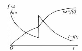
Fig.4.25. Starting current curves of an asynchronous motor with
using a resistor in the stator circuit.
The introduction of active resistances into the rotor circuit reduces the motor currents and increases the starting torque up to (see Fig. 4.7). The circuits for switching on the stages of starting resistors are shown in Fig. 4.2, 6.
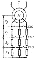
Rice. 4.26. Schemes for switching on starting resistors of asynchronous
engine.
4.11. Calculation of starting resistors for asynchronous motors
Calculations of starting resistors for asynchronous motors with a phase rotor are similar to calculations of starting resistors for shunt and serial motors. In this case, it must be taken into account that on the working part of the mechanical characteristic of an induction motor, the moment is proportional to the current, therefore, calculations are carried out for moments, and not for current. The value of the maximum starting torque is limited by the dynamic forces in the windings and the heating of the machine. In some cases, this moment is limited by the requirements of technology. The calculation of the resistance of starting resistors can be performed using accurate and approximate methods, an analytical and graphical method. Let's consider an approximate method, which is used for maximum switching torques not exceeding 0.7. The diagram for starting an asynchronous motor in two stages is shown in Fig. 4.28.
Analytical method. If the number of steps m is given, then
switching torque ratio ![]() (4.78)
(4.78)
where is the maximum resistance of the rotor circuit at the moment of switching on, ![]() ; resistance scale
; resistance scale

Fig.4.28. Starting diagram of an asynchronous motor.  , - rotor resistance, ab
After substituting the values and  (4.79)
Segment ab = , and the size of the segment is determined from similar
triangles Oad and ofl:
ad/ao = lf/of;
segments aO = ; lf = 1; jf = , therefore:
ad= ao lf/of = ; .
; .
Thus,
The value must be greater than , i.e. . By analogy with cars direct current(chapter 2 and 3)
define the resistance:
(4.80)
When the number of steps is not set, we take the values of the switching times and , then determine the number of steps m:
(4.81)
(4.82)
where , are the nominal values of EMF and rotor current.
For verification, it is necessary to determine the resistance of the rotor and compare it with the obtained graphical method ![]() (4.83)
(4.83)
4.12. Electric drives with linear electric motors
Currently, about 40-50% of serial electric motors are used in production mechanisms with translational or reciprocating motion of the working body. For conversion rotary motion a variety of devices are used in translation: pneumatic and hydraulic transmission, a pair of "screw - nut"; crank mechanism, pinion and rack, wheel and track structure in transport systems, etc. In addition, such drives, as a rule, use gearboxes, which are the place of additional losses and failures.
Linear electric motors allow direct translational movement without mechanical contact between the primary (usually stator) and secondary (rotor) structures, therefore eliminating the transmission mechanism. At the same time, the kinematic scheme is greatly simplified, reliability and control accuracy are increased, and the linear electric motors themselves are well adapted to executive mechanism, have manufacturability in production and less steel consumption due to low-waste cutting.
In practice, linear DC motors are used (mainly stepper), asynchronous (LAD), synchronous (LSD) and electromagnetic (LEMD). Linear asynchronous motors are gaining popularity due to their design simplicity, low cost, manufacturability, reliability, diversity. constructive solutions. Structurally, LAD is cylindrical and flat.
Figure 4.29 shows a flat LIM device.
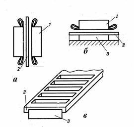
Fig.4.29. The device of flat linear asynchronous motors:
1-inductor with winding (stator); 2 - reactive bus; 3- reverse magnetic circuit; a - bilateral LAD; b - one-sided LAD; c - short-circuited winding with a reverse magnetic circuit.
The LIM movement parameters are controlled in the same way as conventional IM: by changing the resistance of the reactive bus, by regulating the frequency and duration of inclusions. LAD are used in conveyors, agitators of bunkers-feeders of bulk cargoes, vehicles, hand tool and so on. An important advantage LAD consists of high value.