Notes: 1. Volume control - in the maximum volume position; tone controls - roll off low and high frequencies.
2. Range switch - in the “CB” position.
3. The sound generator is connected to pin 27 of the IF-LF board, and the output voltmeter is connected to pin 30 of the board “” of both devices is connected to blade 2 of connector Ш (“tape recorder”).
For check frequency response The ULF frequency on the sound generator is set to 1000 Hz. The volume control at the ULF output sets the voltage to 0.56 V ("Spidola"), 1.1 V ("VEF-12", "VEF-201", "VEF-202") and then the position of the RG does not change. The input voltage (mx) should not exceed 12 mV ("Spidola"), 10 mV ("VEF-12", "VEF-201", "VEF-202"). Then a signal with a frequency of first 200 Hz and then 4000 Hz (playback band) is supplied to the ULF input, and in both cases the voltage u2t is set by the regulator of the output of the generator, which corresponds to the output voltage of 0.56 V (1.1 V). The unevenness of the frequency response N is determined from the ratio N = 20 lg (u2/u1) and should not exceed the standards specified in table. 2. Correction of the frequency response can be carried out by selecting the capacitance of the capacitor C78 ("Spidola"), C73 ("VEF-12", "VEF-201", "VEF-202").
Rice. 70. Structural scheme measuring the input impedance of ULF receivers
1,2 - ULF input; Hin - resistance between points 1 and 2
Sometimes it is useful to know the input impedance of a low-frequency amplifier. For this, a circuit is assembled in accordance with Fig. 70.
The volume control is set to the maximum volume position. From the SG, a signal with a frequency of 1000 Hz is supplied to the base of the first transistor of the low-frequency amplifier through a resistor R1 (2 - 3 kohms) of such a value that the output voltage is 0.56 V ("Spidola") and 1.1 V ("VEF-12" , "VEF-201", "VEF-202"). In this case, the lamp voltmeter (LV1) at the output of the SG will show the voltage value ut, and LV2 - u2 (VLF input). Knowing the value of R1 and the voltages u2 and u1, you can calculate the input resistance of the amplifier (RBX) using the formula:
Rinput= u2 R1/uR1 = u2/(u1-u2) R1,
where uR1 == u1 - u2.
The value of resistor R1 is selected so that it is 2 and 2.
If at the ULF output a voltage corresponding to the rated output power can be obtained at very low input voltages, then this will indicate that the amplifier is close to self-excitation. The reasons for this phenomenon may be positive feedback instead of negative, an open circuit feedback or incorrect wiring of the matching (output) transformer leads. This mode is characterized by a very high nonlinear distortion coefficient and large uneven frequency response.
After completing the ULF adjustment, you need to turn on the supply voltage and check by ear the operation of the low-frequency amplifier at all positions of the volume control. At the position of the RG, corresponding to the minimum volume, there should be no signal at the output of the receiver, and at maximum volume and a ULF signal from the RG with a frequency of 1000 Hz and a value of 15 - 25 mV is supplied to the input, the shape of the output voltage should be undistorted and without kinks, shining brightly points, etc.
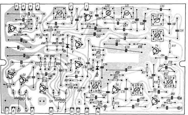
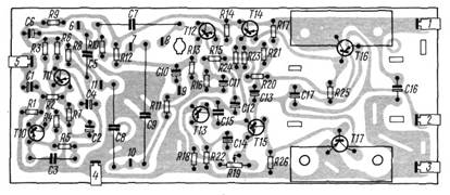
Rice. 2. Wiring diagram of the IF-LF board of the “Spidola”, “VEF-Spidola” and “VEF-Spidola-10” radio receiversResistorR42 installed on the foil side

Rice. 6. Wiring diagram of the IF-LF board of the VEF-12, VEF-201 and VEF-202 radio receivers
ResistorsR10, R22 andR47 installed on the foil side
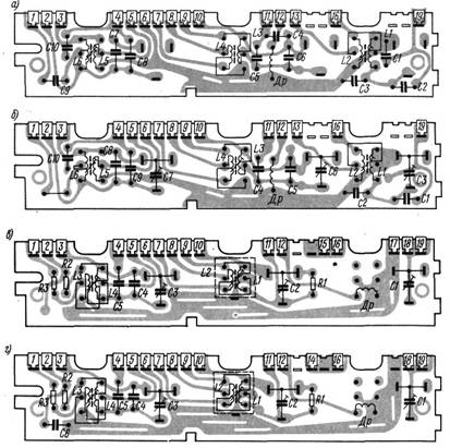
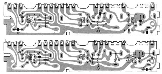
Rice. 10. Wiring diagrams for 25 m range strips - P1
31 m - P2, 41 m - PZ, 49 m - P4 (a), - 50 - 75 g - P5 (b); SV - P6(v) and DV - P7(g) radio receiver "Ocean" On the bands of 25 m (P1) and 31 m (P2) ranges there is no choke (Dr), its connection points are short-circuited with a jumper
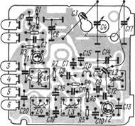
Rice. 11. Wiring diagram of the board of the VHF radio receiver “Ocean”
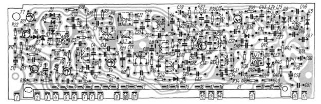
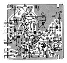
Rice. 12. Wiring diagram of the HF-IF board of the Ocean radio receiver
The diagram does not show the screens of transistors T3, T4, T5, T8 and T9 and the position of the movable knives of switch B1. Points 20 and 21 of the board are connected by a jumper
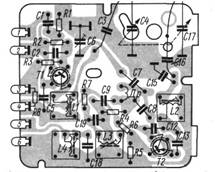
Rice. 13. Wiring diagram of the ULF radio receiver board "Ocean"
Rice. 15. Wiring diagrams of strips for ranges 2o m - P1, 31 m - P2, Im - PZ, 49 m - - P4(a); 50 - 75 m - 115(6) radio receiver "Ocean-203"
On 25 m band bars (III) and 31 l (P2) the throttle (Dr) is missing, its connection points are short-circuited with a jumper
Rice. 16. Wiring diagram of the board of the VHF radio receiver “Ocean-203”
Rice. 1.35 Fig. 1.36 Fig. 1.37 This ends the first stage of solving the problem. Second stage Let's return to the diagram (Fig. 1.31) and for convenience, draw it again (Fig. 1.38). When powered from a single energy source, it is easy to indicate the directions of currents in each resistance (Fig. 1.38). second and third currents: I = I2 +I 3. In this equality, the current of the third resistance is unknown, which is determined as follows: I3 = I − I 2 = 6 − 2 = 4 A. The value of the third resistance is given, and the current in it is found. Consequently, the voltage across this resistance is easy to calculate: U 3 = I 3 R3 = 4 ⋅ 9 = 36 V. 41 The voltage across the fourth resistance U4 is less than the voltage of the second resistance by the amount of voltage applied to the third resistance. Therefore, U4 = U2 – U3 = 84 – 36 = 48 V. In other words, the voltage of the fourth resistance is less than the source voltage by the voltage of the first and third resistances: U 4 = U − (U1 + U 3) = 120 − (36 + 36) = 48 V. Using Ohm’s law, we find the current of the fourth resistance: U 4 48 I4 = = =1 A. R4 48 Let’s apply Kirchhoff’s first law for point a or b. For point a I1 = I 2+ I 4 + I 5, for point at I3 = I 4 + I5. resistance. Then U 6 = U 7 = U 4 − U 5 = 48 − 18 = 30 V, or U 6 = U − (U1 + U 5 + U 3) = 120 − (36 − 18 + 36) = 30 V. Solution Problems of the first type do not cause difficulties, no matter how complex the proposed scheme may seem. Using the considered solution method, you can find the required quantities without much difficulty. 1.2.34. Second type of problem Problems of the second type, in which either the source voltage or any resistance inside the circuit is unknown, are more difficult problems in the sense that it is impossible to indicate in advance the way to solve them for any condition, based only on those solution techniques. which are discussed above. consumers in order to apply this knowledge in the analysis of processes occurring in electrical circuits. You can know the wording of the law, you can list the properties of the circuit for one or another method of connecting consumers. But if you do not understand the processes occurring in circuits when any parameters change, then we can assume that the laws have not been learned and the properties of the circuit are not understood. Check to what extent 43 laws have been mastered direct current and the properties of the circuit with different connections of consumers, very easily. In Fig. 1.40 shown electrical diagram with five resistances. If a student (cadet) correctly explains what happens to the currents in each resistance when one (any) of these resistances decreases or increases, without making any calculations, then we can safely assume that this student (cadet) is good knows the laws of direct current. Of course, he must give this explanation for any diagram, and not just for the image. 1.40 wife in fig. 1.40. Using this diagram as an example, we will show how it is most expedient to carry out such an analysis. decreases in the chain. Accordingly, as any of the circuit resistances increases, the total resistance of the circuit increases. In this case, as the resistance R4 decreases, the total resistance of the circuit decreases, as a result of which the total current (this will be the current of the first resistance I1) will increase. An increase in current I1 causes an increase in the voltage at the first resistance (U1 = I1R1) and a decrease in voltages U2 and U3,4,5, since U2 = U – U1. A decrease in voltage U2 will be accompanied by a decrease in current I 2. The current I 3 will increase, since I 3 = I1 − I 2. As a result of increasing the current I3, the voltage U3 = I3R3 will increase, and the voltage U4 = U5 will decrease, since U4 = U2 – U3. At the same time, U2 decreased and U3 increased. You can also reason like this: U4 = U – (U1 + U3). the algebraic sum of the EMF is equal to the algebraic sum of the voltage drops across the resistances included in this circuit. When composing equations according to Kirchhoff’s second law, they walk around the selected contour in an arbitrary direction. EMF and voltage drops are considered positive (put into the equation with a + sign) if the directions of the EMF and the corresponding currents coincide with the direction of bypassing the circuit; EMF and voltage drop are considered negative if the directions of the EMF and currents in the corresponding resistances are opposite to the direction of bypassing the circuit. Any complex circuit with any number of power supplies can be calculated using Kirchhoff’s laws. When solving such problems, one arbitrarily sets the directions of currents in the branches and composes as many equations as there are unknown quantities (currents, resistance or emf), applying Kirchhoff’s first law for individual branch points and Kirchhoff’s second law for individual internal circuits. We will assume that the current along this branch flows from right to left, and we will denote it by I2. But U, according to the condition, remained unchanged, and U1 and U3 increased. As a result of U, we can draw the following conclusion: the voltages U4 and U5 decreased, thereby the current I 5 = 5 R5 decreased, since R5 did not change. The current I 4 = I 3 − I 5 increased because I3 increased and I5 decreased. 1.2.36. Kirchhoff's second law This law is usually applied when calculating electrical circuits with multiple power sources. For the circuit shown in Fig. 1.41, the voltage between points a and b can be expressed by the following equations: Uav = E1 − I1R1, Uav = E2 − I 2 R2, Uav = I 3 R3. Rice. 1.41 From these equations it is clear that their right-hand sides are equal to each other, i.e. E1 − I1R1 = E2 − I1R1 = E2 − I 2 R2 , (1) whence 44 E1 − E2 = I1R1 − I 2 R2 . Accordingly, we will have: E1 = I1R1 + I 3 R3, E1 = I1R1 + I 3 R3, (2) E2 − I 2 R2 = I 3 R3, E2 = I 2 R2 + I 3 R3. (3) Equations 1–3 express Kirchhoff’s second law, which reads as follows: in any closed loop charge Q has a potential at point b equal to 4 V. What will the potential at point b be equal to if: a) at point c we place a charge equal to charge Q and of the same sign; 48 22. Capacitors are connected according to the indicated diagram. In this case, C1 = C3 = C5 = C6 = 4 µF, and C2 = C4 = 2 µF. The voltage across the fifth capacitor (U5) is 50 V. What is the source voltage? electrical circuit energy?
Answer: 1) at resistance R1; 2) at resistance R2; 3) at resistance R3.
32. Lamps are designed for the same voltage. Which one will give more light?
Answer: 1) lamp No. 1;
2) lamp No. 2;
3) lamp No. 3. 33. What will happen to the current in consumer R2 if consumer R4 is disconnected?
Answer: 1) will increase;
2) will decrease;
3) will not change.
It is easy to check that in this example, putting the capacitance equal to 40 picofarads (this is the capacitance of the piezoelectric elements of the piezo lighter), we obtain that the voltage at a force of 1N will be equal to 6V. If we act with a force of 1000N, we get 6 kV.
2. What is the discharge power of the piezoelectric element? It is extremely difficult to make an accurate calculation, and it makes no sense, but it is interesting to estimate the order of magnitude. The spark current power is the square of the voltage divided by the resistance of the discharge gap. The voltage, of course, changes during the lifetime of the discharge from 3000 volts to almost zero... Therefore, let’s take the average value of 1500 volts. But what is the resistance of the discharge gap? We will roughly estimate it at 1 ohm, since it has been noted that increasing the current lead resistance to 1 ohm reduces the brightness of the spark. Now let's do the calculation.
P =U *U /R =1500*1500/1=2250000 watts=2.25 megawatts
3. What is the energy spent on the spark discharge? This is the energy of the electric field of the piezoelectric element. Let's calculate it using the formula:
W =CU *U /2 in Joules;
We know that the capacitance C is 40 pF, and the voltage U at the beginning of the breakdown is 3000 volts. We calculate the energy W=40*10^(-12)*3000*3000/2=180*10^(-6)=18 0 micro Joules.
Let's calculate the same for 1500 volts, the average breakdown voltage. It is equal to 45 micro Joules.
Let us determine the time during which the discharge will occur:
T =2*R *C =2*1 Ohm*40 pF=80 picoseconds,
Dividing the work of the current by the time it flows, we obtain the following power value:
P =W /T =180 microjoules/80 picoseconds=2250 kilowatts.
4. What is the efficiency of a lighter's piezoelectric generator?
The force varies linearly from 0 to 500 Newton. It can be easily measured using a household steelyard. In the calculation, you should take the average value (250N). Multiplying 250N by 0.002m we get 0.05 J. Then the efficiency will be equal to 0.03%. The question arises: Why is it so small?
5. Let's calculate the current strength.
I =g /T ;g =C *U ;I =C *U /T =40 picofarads * 3000 volts / 80 picoseconds = 1500 Amperes.
This is a rather steep front, and according to all laws, at the moment of formation of an ionized gas channel through which charges flow, they neutralize the local tension of the crystal. The electrical resistance of the feeder channel is an order of magnitude lower than the resistance of copper, therefore there will not be a large thickness of ionized gas. The thickness of the streamer is microns and the volume of ionized gas is minimal.
The inductance of the streamer gap is not known, but it is not important, it is minimal and practically we will accept it as a constant, non-differentiable quantity.
Then the energy magnetic field W =L *I *I /2, over an interval of 80 picoseconds will increase 2.25 million times, since our current flows in a square.
Such a pretty spark)
It spends less than 1/10000 of the power on ionization, and the rest is converted into magnetic field energy.
Does everyone remember the moped running under the window without spark protection?
When neither the TV nor the radio works)))))))
Nothing disappears without a trace. We just don’t know how to use the crystal’s energy to full power, so we’ll be heating our potbelly stoves with banknotes for the rest of our adult lives.