Dear Clients!
When our company sells electric motors for various purposes Consumers have a number of questions regarding their operation and possible problems that may arise during operation.
On this page we have tried to answer the questions that are most frequently encountered.
Three-phase asynchronous electric motors.
How to connect a three-phase asynchronous electric motor with the ability to turn it on from two places?
The connection diagram for an electric motor controlled from two places is not much different from standard motor connection diagram controlled by one post:
It is clear from the diagram that only two more buttons “Start” and “Stop” have been added to it (the posts are circled in red and green dotted lines). Please note that the "Stop" buttons are connected in series with each other, and the "Start" buttons are connected in parallel with each other in the control circuit.
When any “Start” button is pressed, the coil circuit is closed, the coil is retracted, and when the button is opened, the supply voltage to the coil will flow through the KM block contact.
The control circuit is interrupted by pressing any of the "Stop" buttons.
How to connect a three-phase asynchronous electric motor with the possibility of its reversible use?
This circuit is often used to connect three-phase asynchronous electric motor where to control the rotation of the motor shaft - for example, in garage doors, pumps, various loaders, beam cranes, etc.
To reverse the electric motor, a circuit is implemented that changes phasing its supply voltage. For example: if the connection of the electric motor phases is conditionally taken as L1, L2,L3, then the direction of shaft rotation will be opposite than when connected with phasing L3, L2,L1.
Feature reverse circuit connection there is the use of two magnetic starters. At the same time, the main power contacts of the magnetic starters are connected to each other so that when the coil of the first starter is triggered, the phasing of the supply voltage of the electric motor will differ from the phasing when the coil of the other is triggered.

When the first starter KM1 is triggered, its power contacts are attracted (circled in green dotted line) and voltage with phasing L1, L2, L3 is supplied to the motor windings. When the second starter - KM2 - is triggered, the voltage to the engine will go through its power contacts KM2 (circled in red dotted line) and will already have phasing L3, L2, L1.
Magnetic starters are connected via standard scheme. Only the normally closed block contact of another starter is connected in series to the circuit of each coil. This will prevent the circuit from closing if you mistakenly press both Start buttons at the same time.
How to connect a three-phase asynchronous electric motor to a single-phase household network?
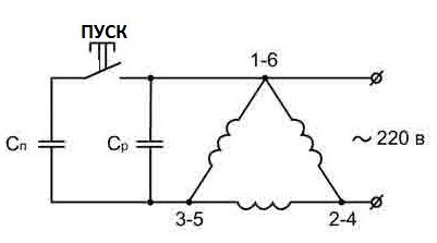
Of course it is possible and the most frequent and simpler method of connecting a three-phase electric motor to a single-phase network ( in the absence of a supply voltage of ~ 380 V), this is the use of a phase-shifting capacitor, through which the third winding of the electric motor is powered. We described this more fully in the article “ Connecting a three-phase electric motor to a household network"

Before connecting a three-phase electric motor to a single-phase network, make sure that the electric motor is connected in a delta (see figure below, option 2 ), this connection causes minimal losses power three-phase motor when you plug it into the network ~ 220 V.
The power that a three-phase electric motor can produce when connected to a single-phase network using a delta winding connection diagram can be up to 75% of its rated value. And the rotation speed of the electric motor does not differ from its frequency when operating in passport mode (3 phases 380V).
Below are examples of connecting terminal blocks of three-phase asynchronous electric motors 1-star, 2-delta, but I should note that their appearance is not always the same; in the connection box there may simply be two separated bundles of wires with three wires each.
These bundles of wires are the beginning and end of the motor windings, “ring” them, separate the windings from each other and connect them in series, when the end of one winding is connected to the beginning of the other - this is the “triangle” connection (C1-C6, C2-C4 , C3-C5). Add a starting capacitor Sp (used briefly during startup) and a running capacitor to the switching circuit WITH R.

If you have an engine with a power of up to 1.5 kW, for the SB button you can use a regular “start” button from the control circuits of magnetic starters, but if the power is higher, it is better to use a more powerful switching device, such as an automatic machine, in which case you will have to manually turn off starting capacity Sp after the electric motor gains speed.
In the circuit below, the possibility of two-stage control of the electric motor is implemented, which allows you to reduce the total capacitance of the capacitors as the electric motor speed increases.

I also note that if your electric motor has a power of up to 1 kW, the starting capacitor can be completely removed from the circuit.
To calculate the capacity of the working capacitor, I propose the following formulas:
"Triangle" - Serb=4800xI/U, µF
"Star" - C slave = 2800. I/U, µF
These are more accurate methods that require measuring the current in the motor circuit.
However, knowing the rated power of the electric motor, you can use the following formula:
C slave = 66 R n, µF, where R n- and there is the rated power of the engine.
Simply put, every 0.1 kW of electric motor power is 7 µF of a working capacitor.
Power 1.1 kW – capacity 77 µF.
This capacitance is usually collected by several capacitors, which are connected to each other in parallel (the total capacitance is equal to the total), types of capacitors: MBGCh, BGT, KBG, the operating voltage should exceed the network voltage by 1.5 times.


Knowing the capacity of the working capacitor, we determine the starting capacitor; its capacity should exceed the capacity of the working one on average by 2-3 times; use capacitors for starting of the same types as the working ones. As a last resort, if the start is very short, you can use electrolytic ones - types K50-3, KE-2, EGC-M, with a voltage of at least 450 V.
Are there protection systems that can increase the service life of an electric motor?
Of course they exist, and they were not invented yesterday, in answer to the first question, we general outline gave examples correct inclusion electric motor, not leading to emergency mode operation and, as a consequence, damage to the electric motor and its premature failure. But we would like to cover this issue in more detail.
So before we move on to the methods motor protection it is necessary to consider the most frequent and basic reasons for emergency operationasynchronous electric motors:
1. Single-phase and interphase short circuits- in the cable, electric motor terminal box, stator winding (on the housing, interturn short circuits).
Attention! Short circuit (short circuit) is the most dangerous and common view malfunctions in the electric motor, as it is accompanied by the occurrence of very high currents, leading to overheating and burning of the stator windings.
2. Thermal overload of the electric motor-occur when the rotation of the shaft is very difficult (bearing failure, debris getting into the auger, starting the engine under too much load, or stopping it completely).
Most common cause thermal overload of the electric motor leading to abnormal operation is disappearance one of the supply phases. This causes a significant increase in current (twice the rated current) in the stator windings of the other two phases.
As a result of thermal overload of the electric motor, very strong overheating and destruction of the general insulation of the stator windings occurs, leading to short-circuiting of the windings and complete inoperability of the electric motor.
So how to protect an electric motor? from current overloads?
Main secret consists of timely de-energizing the electric motor when large currents appear in its power circuit or control circuit, i.e., when short circuits occur.
To protect electric motors from short circuits the most commonly used are fuses (fuses), electromagnetic relays, automatic switches with an electromagnetic break, selected so that they can withstand high starting currents, but were immediately triggered when short circuit currents appeared.
If the task is protect the electric motor from thermal overload used in the electric motor connection diagram thermal relay, which has in its execution control circuit contacts– through which supply voltage is supplied to the coil of the magnetic starter.
If thermal overloads occur, these contacts will open and interrupt the power supply to the coil, which will lead to the return of the group of power contacts to their original position - the electric motor is de-energized.
In the simplest and most trouble-free way protection of the electric motor against phase loss There will be an additional magnetic starter added to the electric motor connection diagram:

When turning on the circuit breaker 1 the power circuit of the magnetic starter coil is closed 2 (in this case, the operating voltage of the specified coil should be ~ 380 volts) and closing the power contacts 3 starter, through which (only one contact is used) power is supplied to the coil of the magnetic starter 4 .
Enable the Start button 6 directly through the "Stop" button 8 causes the coil power circuit to short-circuit 4, the next magnetic starter (its operating voltage is both 380 and 220 V), closes its power contacts 5, and voltage is supplied to the motor.
If you press the "Start" button 6, voltage from power contacts 3 will pass through a normally open block contact 7 , while ensuring continuity of the power supply circuit of the magnetic starter coil.
As you can see from this scheme motor protection, the absence (for any reason) of any of the phases of voltage supplied to the electric motor will de-energize the electric motor, which will save it from thermal overloads and premature failure.
Without going into detail about the basic theory of electrical engineering, we note the main thing - electric motors with star-connected windings operate much softer than electric motors with a delta-connected winding, but it should be noted that when the windings are connected by a star, the motor is not able to produce maximum power. If the windings are connected in a delta, the motor will produce full rated power (approximately 1.5 times higher than with a star connection), but the starting currents will be high.
Therefore, it is most desirable (in particular, this is very important for electric motors) high power) star-delta connection; in this case, the electric motor starts according to the star circuit, after which (when the electric motor “reaches its rated speed”), it automatically switches to the delta connection circuit.
In this case, the control scheme should look like this:

When connecting the operational voltage through the NC (normally closed) contact of the time relay K1 and the NC contact K2, in the starter coil circuit K3.
When the starter K3 is turned on, it opens contact K3 in the coil circuit of the starter K2 (blocking accidental activation) and closes contact K3 in the coil circuit of the magnetic starter K1 - it is combined with the contacts of the time relay.
When the starter K1 is turned on, contact K1 closes in the coil circuit of the magnetic starter K1 and at the same time the time relay turns on, the time relay contact K1 opens in the coil circuit of the starter K3, and the time relay contact K1 closes in the coil circuit of the starter K2.
Disabling the starter K3, contact K3 closes in the coil circuit of the magnetic starter K2. Turning on the K2 starter opens the K2 contact in the K3 starter coil circuit.

The beginnings of the windings U1, V1 and W1 are supplied with operating voltage through the power contacts of the magnetic starter K1. The magnetic starter K3 is triggered by its power contacts K3, thus connecting the ends of the windings U2, V2 and W2 - the motor windings are star-connected.
Next, the time relay, combined with the starter K1, is activated, turning off the starter K3 and simultaneously turning on K2 - the power contacts of K2 are closed and voltage is supplied to the ends of the motor windings U2, V2 and W2. The electric motor is now switched on in a delta configuration.
How to correctly connect a three-phase asynchronous electric motor to the mains supply?
Regular scheme connecting a three-phase asynchronous electric motor consists of the following elements:
· magnetic starter and overcurrent protection (circuit breaker - automatic).
The connection diagrams themselves may be different and depend on:
· type of magnetic starter, and more specifically - from the operating voltage of its coil K (220 V or 380 V);
· from the presence of a thermal relay, which is connected in series with the starter coil. Exceeding the current consumed by the electric motor causes the contacts of the thermal relay to open, which leads to de-energization of the coil and shutdown of the electric motor.
Connection diagrams for a three-phase electric motor


Symbols on diagrams:
1 - automatic switch (3-pole circuit breaker),
2 - thermal relay with normally open contacts,
3 - group of magnetic starter contacts,
4 - magnetic starter coil (in this case, the operating voltage of the coil is 220 V), 5 - normally open block contact,
6 - "Start" button,
7 - "Stop" button.
The difference between these circuits for connecting electric motors is the use of different magnetic starters in these circuits. In the first case it is used magnetic switch with coil operating voltage 4 - 220 V; to power it, phase C is used (any other phase can be used) and zero - N.
In the second case, the electric motor is connected through a magnetic starter with a coil 4 at 380 V. To power it, phases B and C are used.
Motor connection
Often you have to look for diagrams for connecting an electric motor to a 220 or 380 volt network for your own needs, which do not comply with the equipment’s specifications. Although this approach implies a decrease in efficiency, it is sometimes justified. This block contains the most accessible and technically sound diagrams for connecting a motor to a three-phase and single-phase network.
If in single-phase electric motors only one winding is placed (according to the number of phases), then the field inside the stator will not be rotating, but pulsating, and starting or pushing will not occur unless the shaft is untwisted by hand. To allow rotation to occur without manual intervention, an auxiliary winding was added - a starting winding. It is the second phase, shifted by 90 degrees, pushing the rotor at the moment of switching on, but since the motor is connected to a single-phase network, it is still called single-phase. Now single-phase asynchronous electric motors have two windings - working and starting. The starting winding is turned on a short time only to start the shaft (no more than 3 seconds). The working one is always on. You can determine the winding terminals using a tester. The figure shows the relationship between the windings and the common terminal. To start the motor, you need to apply 220 volts to both windings and, after gaining speed, immediately turn off the starting winding. To shift the phase, ohmic resistances, capacitors and inductances are used. Moreover, the resistance may not be in the form of a separate resistor, but part of the starting winding, wound using bifilar technology, when the inductance of the coil remains the same, and its resistance increases due to longer copper wire. Connection diagram single-phase electric motor shown in Figure 1.
There are motors in which the working and auxiliary windings are constantly connected to the electrical network. Essentially, they are two-phase. The field inside the stator rotates. The capacitor in this case serves to shift the phases. In such a system, both windings are made of wire of the same cross-section.
Connecting a three-phase electric motor
As you know, three-phase motors have higher efficiency than single-phase and two-phase ones. A rotating magnetic field in the stator appears immediately after being connected to a 380-volt network without the help of starting devices. Two common electric motor connection schemes are star and delta, as shown in Figure 2.

It should be noted that when connected with a star, the start will be smooth, but it is impossible to achieve this maximum power operation of the electric motor. When connected with a triangle, the motor will produce its full rated power, which is 1.5 times more than when connected with a star, but during startup the current is so high that it can damage the insulation of the wires. Therefore for powerful engines apply combined scheme star-delta connections. Starting occurs according to the star circuit (starting currents are small), and after the electric motor enters the operating state, automatic or manual switching to a triangle circuit (power increases by 1.5 times and approaches the nominal). Switching is done using magnetic starters, a starting time relay or a packet switch. The connection diagram to the 380 volt network is shown in Figure 3. With the keys K1 and K3 closed, the engine is connected in a star circuit, and with the keys K1 and K2 closed, the engine is connected in a triangle.
Connecting a three-phase motor to a single-phase network through a capacitor (380 to 220)
In practice, it is often necessary to connect a three-phase motor to a 220 volt network. Although the efficiency drops to 50% (in best case scenario up to 70%), such alteration may be justified. In fact, the motor begins to work as a two-phase one. This is done according to a star or delta circuit using a working and starting capacitor, which serve for phase shift and acceleration (Figure 4). The acceleration button must be held until the shaft spins up to maximum, and then released. Capacitors are calculated using formulas.
For a star, Cp = 2800 x I / U (µF);
For a triangle, Cp = 4800 x I / U (uF);
Sp = Av x (2...3).
Where I is the current consumed by the motor (measured manually), U is the supply voltage equal to 220V.

The difficulty is that under load and when idling The current flowing through the windings is different, which means that the capacitance will need to be selected experimentally for a specific load. If the capacity is larger than needed, the motor will overheat. To approximately determine the ratings based on the power of the electric motor, use this table.
 The voltage of the capacitors must be at least 1.5 times greater, otherwise they may fail due to voltage surges at the moment of switching on and off. If it is difficult to obtain metal-paper capacitors of the required capacity, some use electrolytic capacitors, soldered according to a special circuit with diodes. But you need to be careful and close them in a housing so that in the event of an explosion, the electrolyte does not get into your eyes. You also need to take into account that by connecting the circuit, as shown in Figure 5, the capacitance is halved. You still need to understand that in order to operate powerful machines, you should avoid replacing metal-paper capacitors with electrolytic ones.
Three-phase motor connection diagrams - motors designed to operate from three-phase network, have a performance much higher than single-phase 220 volt motors. Therefore, if three phases are carried out in the workroom alternating current, then the equipment must be installed taking into account the connection to three phases. As a result, a three-phase motor connected to the network provides energy savings and stable operation of the device. No need to connect additional elements for start. The only condition for good operation of the device is error-free connection and installation of the circuit, in compliance with the rules.
Three-phase motor connection diagrams
Of the many schemes created by specialists, two methods are practically used for installing an asynchronous motor.
1. Star diagram.
2. Triangle diagram.
The names of the circuits are given according to the method of connecting the windings to the supply network. To determine on an electric motor which circuit it is connected to, you need to look at the specified data on a metal plate that is installed on the motor housing.
Even on old motor samples you can determine the connection method stator windings, as well as the mains voltage. This information will be correct if the engine has already been in operation and there are no operational problems. But sometimes you need to make electrical measurements.
Star connection diagrams for a three-phase motor make it possible to start the motor smoothly, but the power is 30% less than the rated value. Therefore, in terms of power, the triangle circuit remains the winner. There is a feature regarding the current load. The current increases sharply during startup, this negatively affects the stator winding. The generated heat increases, which has a detrimental effect on the winding insulation. This leads to insulation failure and damage to the electric motor.
Many European devices supplied to domestic market, are equipped with European electric motors operating with voltages from 400 to 690 V. Such 3-phase motors must be installed in a 380 volt network of domestic voltage only according to the triangular pattern of stator windings. Otherwise, the motors will immediately fail. Russian motors for three phases are connected in a star. Occasionally, a triangle circuit is installed to obtain from the engine highest power, used in special types industrial equipment.
Manufacturers today make it possible to connect three-phase electric motors according to any circuit. If there are three ends in the mounting box, then the factory star circuit has been produced. And if there are six terminals, then the motor can be connected according to any scheme. When mounting in a star, you need to combine the three terminals of the windings into one unit. The remaining three terminals are supplied to phase power with a voltage of 380 volts. In a triangle circuit, the ends of the windings are connected in series in order to each other. Phase power is connected to the node points of the ends of the windings.
Checking the motor connection diagram
Let's imagine the worst case scenario for connecting the windings, when the wire terminals are not marked at the factory, the circuit assembly is carried out in the inside of the motor housing, and one cable is brought out. In this case, it is necessary to disassemble the electric motor, remove covers, disassemble inner part, deal with the wires.
Stator phase determination method
After disconnecting the lead ends of the wires, use a multimeter to measure the resistance. One probe is connected to any wire, the other is brought in turn to all wire terminals until a terminal belonging to the winding of the first wire is found. Do the same for the other terminals. It must be remembered that marking the wires in any way is mandatory.
If there is no multimeter or other device available, then use homemade probes made from a light bulb, wires and batteries.
Winding polarity
To find and determine the polarity of the windings, you need to apply some techniques:
• Connect pulsed direct current.
• Connect an alternating current source.
Both methods operate on the principle of applying voltage to one coil and transforming it along the magnetic circuit of the core.
How to check the polarity of the windings with a battery and a tester

A voltmeter with increased sensitivity is connected to the contacts of one winding, which can respond to a pulse. Voltage is quickly connected to the other coil with one pole. At the moment of connection, the deviation of the voltmeter needle is monitored. If the arrow moves to the positive, then the polarity coincides with the other winding. When the contact opens the arrow will go to the minus. For the 3rd winding the experiment is repeated.
By changing the terminals to another winding when the battery is turned on, it is determined how correctly the markings of the ends of the stator windings are made.
AC test
Any two windings are connected in parallel with their ends to the multimeter. The voltage is turned on to the third winding. They look at what the voltmeter shows: if the polarity of both windings matches, then the voltmeter will show the voltage value, if the polarities are different, then it will show zero.
The polarity of the 3rd phase is determined by switching the voltmeter, changing the position of the transformer to another winding. Next, control measurements are made.
Star diagram
This type of motor connection circuit is formed by connecting the windings into different circuits, connected by neutral and common point phases.
Such a circuit is created after the polarity of the stator windings in the electric motor has been checked. A single-phase voltage of 220V is supplied through a machine to the beginning of 2 windings. Capacitors are inserted into the gap into one: working and starting. The stars are brought to the third end neutral wire nutrition.

The capacitance value of capacitors (working) is determined by the empirical formula:
C = (2800 I) / U
For the starting circuit, the capacity is increased by 3 times. When the motor is operating under load, it is necessary to control the magnitude of the winding currents by measurements, adjust the capacitance of the capacitors according to medium load mechanism drive. Otherwise, the device will overheat and an insulation breakdown will occur.
It is best to connect the motor to operation through the PNVS switch, as shown in the figure.

It already contains a pair of closure contacts, which together supply voltage to 2 circuits by means of the “Start” button. When the button is released, the circuit breaks. This contact is used to start the circuit. A complete power shutdown is done by clicking on “Stop”.
Triangle diagram
The diagram for connecting a three-phase motor with a delta is a repetition of the previous version in startup, but differs in the method of connecting the stator windings.
The currents passing through them more values star chains. The operating capacitances of capacitors require increased rated capacitances. They are calculated using the formula:
C = (4800 I) / U
The correct choice of capacitances is also calculated by the ratio of currents in the stator coils by measuring with a load.
Motor with magnetic starter
A three-phase electric motor operates via similar scheme with automatic switch. This circuit additionally has an on and off block, with Start and Stop buttons.

One phase, normally closed, connected to the motor, is connected to the Start button. When it is pressed, the contacts close and current flows to the electric motor. It must be taken into account that when the Start button is released, the terminals will open and the power will turn off. To prevent this situation from happening, the magnetic starter is additionally equipped with auxiliary contacts, which are called self-retaining. They block the chain and prevent it from breaking when the Start button is released. You can turn off the power using the Stop button.
As a result, a 3-phase electric motor can be connected to the network three-phase voltage absolutely different methods, which are selected according to the model and type of device, operating conditions.
Connecting a motor from a machine
A general version of this connection diagram looks like in the figure:

Shown here is a circuit breaker that turns off the power supply to the electric motor when there is excessive current load, and short circuit. The circuit breaker is a simple 3-pole switch with thermal automatic characteristic workload.
For an approximate calculation and assessment of the required thermal protection current, it is necessary to double the rated power of a motor designed to operate from three phases. The rated power is indicated on a metal plate on the motor housing.
Such connection diagrams for a three-phase motor may well work if there are no other connection options. The duration of the work cannot be predicted. It's the same if you twist it aluminum wire with copper. You never know how long it will take for the twist to burn out.
When using such a scheme, you need to carefully select the current for the machine, which should be 20% greater than the operating current of the motor. Select the thermal protection properties with a reserve so that the blocking does not work during startup.
If, for example, the motor is 1.5 kilowatts, the maximum current is 3 amperes, then the machine needs at least 4 amperes. The advantage of this motor connection scheme is low cost, simple design and maintenance. If the electric motor is in the same number and works a full shift, then there are the following disadvantages:
- It is impossible to adjust the thermal current of the circuit breaker. To protect the electric motor, current protective shutdown the machine is set to 20% more operating current according to the motor rating. The motor current needs to be through certain time measure with clamps, adjust the thermal protection current. But a simple circuit breaker does not have the ability to adjust the current.
- The electric motor cannot be turned off and on remotely.
Theoretical material presented in the first part of the topic dedicated to single-phase connection three-phase electric motor, designed so that the home master can consciously translate industrial devices 380 volt network for household electrical wiring 220.
Thanks to it, you will not just mechanically repeat our recommendations, but will implement them consciously.
Optimal diagrams for connecting a three-phase motor to a single-phase household network
Among the many ways to connect an electric motor in practice, only two are widely used, called briefly:
- star;
- triangle.
The name is given by the method of connecting windings in an electrical circuit inside the stator. Both methods differ in that they apply a different voltage to each phase of the motor.
In the star scheme line voltage is supplied to two windings connected in series at once. Their electrical resistance folds up and provides greater resistance to passing current.
In a triangle, linear voltage is applied to each winding individually and therefore has less resistance. Currents are created higher in amplitude.
Let us pay attention to these two differences and draw practical conclusions for their use:
- the star circuit has reduced currents in the windings, allows you to operate the electric motor for a long time with minimal loads, and provide small torques on the shaft;
- more high currents, created by the delta circuit, provides better power output, allows the engine to be used under extreme loads, so it requires reliable cooling for long-term operation.
These two differences are explained in detail in the picture. Look at her carefully. For clarity, red arrows specifically mark the incoming voltages from the line (linear) and those applied to the windings (phase). For a triangle circuit they are the same, but for a star they are reduced by connecting two windings through the neutral.

These methods should be analyzed in relation to the operating conditions of your future mechanism at the design stage, before the start of its creation. Otherwise, the motor of the star circuit may not be able to cope with the connected loads and will stop, while the motor of the delta circuit may overheat and eventually burn out. The motor current load can be determined by selecting the connection diagram.
How to find out the connection diagram for the stator windings of an asynchronous motor
At each plant it is accepted on the body electrical equipment place information signs. An example of its implementation for a three-phase electric motor is shown in the photograph.

For the home handyman You may not pay attention to all the information, but only to:
- power consumption: its value is used to judge the performance of the connected drive;
- winding connection diagram - the question has just been sorted out;
- the number of revolutions that may require connecting a gearbox;
- currents in phases - windings are created for them;
- impact protection class external environment- determines operating conditions, including protection from atmospheric moisture.
Factory information can usually be trusted, but it was created for a new engine being sold. This scheme may undergo reconstruction several times during its entire operation, losing its original appearance. Old engine improper storage may lose functionality.
Electrical measurements of its circuit should be performed and the insulation condition should be checked.
How to determine stator winding connection diagrams
To carry out electrical measurements, it is necessary to have access to each end of all three windings. Typically, six of their pins are connected to their own bolts inside the terminal box.
But, among the methods of factory installation, there is one when special asynchronous models are made according to a star circuit so that the neutral point is assembled by the ends of the windings inside the housing, and one core of its assembly is connected to the input box. This option, which is unsuccessful for us, will require unscrewing the studs securing the covers on the body to remove them. Then you need to get to the junction of the windings and disconnect their ends.
Electrical inspection of stator winding ends

After finding both ends for one winding, they must be marked with their own markings for subsequent checks and connections.
Polarity measurements of stator windings
Since the windings are wound in a strictly defined way, we need to accurately find their beginnings and endings. There are two simple electrical methods for this:
- short-term supply direct current in one winding to create a pulse;
- use of a source of variable EMF.
In both cases the principle works electromagnetic induction. After all, the windings are assembled inside a magnetic circuit, which ensures good transformation of electricity.
Battery pulse test
The work is performed on two windings at once. The picture shows this process for three - so it's less to draw.

The process consists of two stages. First, unipolar windings are determined, and then a control check is carried out to eliminate possible error of the measurements taken.
To search for unipolar terminals, a DC voltmeter switched to the limit of the sensitive scale is connected to any free winding. We will use it to implement , which appears due to the transformation of the impulse.
The negative terminal of the battery is rigidly connected to an arbitrary end of the second winding, and the positive terminal is briefly touched to its second end. This moment is shown in the picture by the contact of the button.
Observe the behavior of the voltmeter needle, which reacts to the supply of an impulse in its circuit. It can move towards plus or minus. The coincidence of the polarities of both windings will be shown by a positive deviation, and the difference - negative.
When the pulse is removed, the arrow will go to reverse side. They also pay attention to this. Then the ends are marked.
After this, the measurement is performed on the third winding, and the control check is carried out by switching the battery to another circuit.
Testing with a step-down transformer
It is recommended to use a 24 volt AC EMF source to ensure electrical safety. It is not recommended to neglect this requirement.
First, take two arbitrary windings, for example, No. 2 and No. 3. Connect their terminals together in pairs and connect a voltmeter, but with alternating current, to these places. The remaining winding No. 1 is supplied with voltage from the step-down transformer and the readings from it appear on the voltmeter.

If the vectors are directed equally, then they will not influence each other and the voltmeter will show their total value - 24 volts. When the polarity is reversed, then on the voltmeter the opposing vectors will add up and add up to the number 0, which will be displayed on the scale as an arrow. Immediately after measuring, the ends should also be marked.
Then you need to check the polarity for the remaining pair and perform a test measurement.
So simple electrical experiments you can reliably determine the belonging of the ends to the windings and their polarity. This will help to assemble them correctly for the capacitor starting circuit.
Checking the insulation resistance of the stator windings
If the engine was stored in unheated room, then he was in contact with moist air, damp. Its insulation is broken and can create leakage currents. Therefore, its quality must be assessed by electrical measurements.
A tester in ohmmeter mode is not always able to detect such a violation. It will only show an obvious defect: the power of its current source is too low and does not provide an accurate measurement result. To check the insulation condition, you must use a megohmmeter - a special device with a powerful power source that provides application to the measuring circuit high voltage 500 or 1000 volts.
An assessment of the insulation condition must be carried out before applying operating voltage to the windings. If leakage currents are detected, you can try to dry the engine in a warm, well-ventilated environment. Often this technique allows you to restore functionality electrical diagram, assembled inside the stator core.
Starting an asynchronous motor according to a star circuit
For this method, the ends of all windings K1, K2, K3 are connected at the neutral point and are isolated, and line voltage is applied to their beginnings.

The working zero of the network is rigidly connected to one beginning, and the phase potential to the other two in the following way:
- the first winding is rigidly connected;
- the second cuts through the capacitor assembly.
For a stationary connection of an asynchronous motor, it is necessary to first determine the phase and working zero of the supply network.
How to choose capacitors
The electric motor starting circuit uses two chains to connect the winding through capacitor assemblies:
- working - connected in all modes;
- starting - used only for intensive rotation of the rotor.
At the moment of startup, both of these circuits operate in parallel, and when brought into operating mode, the starting circuit is turned off.
The capacity of the working capacitors must correspond to the power consumption electric motor. To calculate it, use the empirical formula:
C slave=2800∙I/U.
The quantities included in it rated current I and voltage U are precisely what makes the adjustment according to electrical power engine.
The capacity of starting capacitors is usually 2–3 times higher than the working one.
The correct selection of capacitors affects the formation of currents in the windings. They must be checked after starting the engine under load. To do this, measure the currents in each winding and compare them in magnitude and angle. Good operation carried out with the minimum possible distortion. Otherwise, the engine will run unstably, and one or two windings will begin to overheat.
IN starting circuit switch SA is shown, which puts the starting capacitor into operation for a short start-up time. There are many button designs that allow you to perform this operation.
However, I would like to draw your attention to a special device produced in Soviet times industry for washing machines with an activator - a centrifuge.

Its closed case contains a mechanism consisting of:
- two contacts that close when the top “Start” button is pressed;
- one contact that opens the entire circuit from the “Stop” button.
When you press the Start button, the circuit phase is supplied to the engine through working capacitors in one chain and starting capacitors in another. When the button is released, one contact is broken. It is connected to the starting capacitors.
Starting an asynchronous motor using a triangle pattern
There are practically no big differences between this method and the previous one. The starting and working chains operate according to the same algorithms.

In this circuit, it is necessary to take into account the increased currents flowing in the windings and other methods of selecting capacitors for them.
Their calculation is carried out using a formula similar to the previous one, but different:
C slave=4800∙I/U.
The relationship between the starting and running capacitors does not change. Do not forget to evaluate their selection by control measurements of currents under rated load.
Final conclusions
- Existing technical methods allow you to connect three-phase asynchronous motors to a single-phase 220 volt network. Numerous researchers offer a wide range of experimental schemes for this purpose.
- However, this method does not ensure efficient use of electrical power resources due to large energy losses associated with poor-quality voltage conversion for connection to the stator phases. Therefore, the engine operates with low efficiency and increased costs.
- Long-term operation of machines with such engines is not economically justified.
- The method can only be recommended for connecting non-critical mechanisms for a short period of time.
- With the aim of effective use of an asynchronous electric motor, it is necessary to use full three-phase connection or a modern expensive inverter converter of appropriate power.
- Single-phase electric motor with the same power in household network it will cope with all tasks better, and its operation will be cheaper.
Thus, the designs asynchronous motors, previously massively connected to home wiring, are not popular now, and the method of connecting them is outdated and rarely used.

A variant of such a mechanism is shown in a photograph of an emery board with the protective shield and limit stop removed for clarity. Even with this design, it is difficult to work on it due to power losses.
Practical advice from Alexander Shenrok, presented in his video, clearly complements the material in the article and allows you to better understand this topic. I recommend viewing it, but be critical of measuring the insulation resistance with a tester.
Ask questions in the comments, share the article with friends via social network buttons.
Most often, our houses, plots, garages are connected single-phase network 220 V. Therefore, equipment and all homemade products are made so that they work from this power source. In this article we will look at how to make the connection correctly single phase motor.
Asynchronous or collector: how to distinguish
In general, you can distinguish the type of engine by the plate - the nameplate - on which its data and type are written. But this is only if it has not been repaired. After all, anything can be under the casing. So if you are not sure, it is better to determine the type yourself.
How do collector motors work?
You can distinguish between asynchronous and commutator motors by their structure. The collectors must have brushes. They are located near the collector. Another mandatory attribute of this type of engine is the presence of a copper drum, divided into sections.
Such motors are produced only single-phase; they are often installed in household appliances, since they allow you to get big number rpm at the start and after acceleration. They are also convenient because they easily allow you to change the direction of rotation - you just need to change the polarity. It is also easy to organize a change in the rotation speed by changing the amplitude of the supply voltage or its cutoff angle. That is why such engines are used in most household and construction equipment.

The disadvantages of commutator motors are high operating noise at high speeds. Remember a drill, an angle grinder, a vacuum cleaner, a washing machine, etc. The noise during their operation is decent. At low speeds brushed motors not so noisy ( washing machine), but not all tools work in this mode.
The second unpleasant point is that the presence of brushes and constant friction leads to the need for regular Maintenance. If the current collector is not cleaned, contamination with graphite (from brushes being worn out) can cause adjacent sections in the drum to become connected and the motor simply stops working.
Asynchronous
An asynchronous motor has a starter and a rotor, and can be single or three phase. In this article we consider connecting single-phase motors, so we will only talk about them.
Asynchronous motors are characterized by a low noise level during operation, therefore they are installed in equipment whose operating noise is critical. These are air conditioners, split systems, refrigerators.

There are two types of single-phase asynchronous motors - bifilar (with a starting winding) and capacitor. The whole difference is that in bifilar single-phase motors the starting winding works only until the motor accelerates. Then it turns off special device- centrifugal switch or start-protection relay (in refrigerators). This is necessary, since after overclocking it only reduces efficiency.
In capacitor single-phase motors, the capacitor winding runs all the time. Two windings - main and auxiliary - are shifted relative to each other by 90°. Thanks to this, you can change the direction of rotation. The capacitor on such engines is usually attached to the housing and is easy to identify by this feature.
You can more accurately determine the bifolar or capacitor motor in front of you by measuring the windings. If the resistance of the auxiliary winding is less than half (the difference can be even more significant), most likely this is a bifolar motor and this auxiliary winding is a starting winding, which means that a switch or starting relay must be present in the circuit. In capacitor motors, both windings are constantly in operation and connecting a single-phase motor is possible through a regular button, toggle switch, or automatic machine.
Connection diagrams for single-phase asynchronous motors
With starting winding
To connect a motor with a starting winding, you will need a button in which one of the contacts opens after switching on. These opening contacts will need to be connected to the starting winding. In stores there is such a button - this is PNDS. Its middle contact closes for the holding time, and the two outer ones remain in a closed state.

Appearance of the PNVS button and the state of the contacts after the “start” button is released"
First, using measurements, we determine which winding is working and which is starting. Typically the output from the motor has three or four wires.
Consider the option with three wires. In this case, the two windings are already combined, that is, one of the wires is common. We take a tester and measure the resistance between all three pairs. The working one has the lowest resistance, the average value is the starting winding, and the highest is the common output (the resistance of two windings connected in series is measured).
If there are four pins, they ring in pairs. Find two pairs. The one with less resistance is the working one, the one with more resistance is the starting one. After this, we connect one wire from the starting and working windings, output common wire. A total of three wires remain (as in the first option):
- one from the working winding is working;
- from the starting winding;
- general.
With all these 
connecting a single-phase motor
We connect all three wires to the button. It also has three contacts. Be sure to place the starting wire on the middle contact(which is closed only during start-up), the other two are extremelyie (arbitrary). We connect to the extreme input contacts of the PNVS power cable(from 220 V), we connect the middle contact with a jumper to the working one ( note! not with the general). That's the whole circuit for switching on a single-phase motor with a starting winding (bifolar) through a button.
Condenser
When connecting a single-phase capacitor motor, there are options: there are three connection diagrams and all with capacitors. Without them, the engine hums, but does not start (if you connect it according to the diagram described above).
The first circuit - with a capacitor in the power supply circuit of the starting winding - starts well, but during operation the power it produces is far from rated, but much lower. The connection circuit with a capacitor in the connection circuit of the working winding gives the opposite effect: not very good performance at start-up, but good performance. Accordingly, the first circuit is used in devices with heavy starting (for example), and with a working capacitor - if good performance characteristics are needed.
Circuit with two capacitors
There is a third option for connecting a single-phase motor (asynchronous) - install both capacitors. It turns out something between the options described above. This scheme is implemented most often. It is in the picture above in the middle or in the photo below in more detail. When organizing this circuit, you also need a PNVS type button, which will connect the capacitor only during the start time, until the motor “accelerates”. Then two windings will remain connected, with the auxiliary winding through a capacitor.

Connecting a single-phase motor: circuit with two capacitors - working and starting
When implementing other circuits - with one capacitor - you will need regular button, automatic or toggle switch. Everything connects there simply.
Selection of capacitors
There is a rather complex formula by which you can calculate the required capacity accurately, but it is quite possible to get by with recommendations that are derived from many experiments:
- The working capacitor is taken at the rate of 0.7-0.8 µF per 1 kW of engine power;
- starting - 2-3 times more.
The operating voltage of these capacitors should be 1.5 times higher than the network voltage, that is, for a 220 V network we take capacitors with an operating voltage of 330 V and higher. To make starting easier, look for a special capacitor in the starting circuit. They have the words Start or Starting in their markings, but you can also use regular ones.
Changing the direction of motor movement
If, after connecting, the motor works, but the shaft does not rotate in the direction you want, you can change this direction. This is done by changing the windings of the auxiliary winding. When assembling the circuit, one of the wires was fed to the button, the second was connected to the wire from the working winding and the common one was brought out. This is where you need to switch the conductors.
