Electric cars direct current.
Design of electrical machines
Direct current. Reversibility of machines
According to their purpose, DC electric machines are divided into generators and motors.
Generators produce electrical energy that goes into the power grid; motors create mechanical torque on the shaft, which is used to drive various mechanisms and Vehicle.
Delgas calls which makes it indispensable for the construction of engines in the transport industry. The commutator has the same number of coils as the induced winding of the machine. brass or brass. There is, however. isolated from each other by a layer of varnish or oxide. Magnetic head made of sheet metal has a slot on its outer surface where the induced winding of the machine is located. based on sheets of iron.
The conductors and grooves usually run parallel to the axis, but in other cases they are inclined. The circumference of the grooves for placing the armature winding conductors. Electric traction motors have two operating modes: continuous and hourly. Everything exists larger number industrial processes that require precision control or a range of speeds that cannot be achieved using motors alternating current. rolls of paper. Bypass motors are used. transportation by water. IN last years it is increasingly used with variable speed machines where a large amount of speed and control is required.
Electric machines are reversible. This means that the same machine can work both as a generator and as an engine. Therefore, we can talk about the design of DC machines without separately considering the design of the generator or engine.
The property of reversibility should not be opposed to the specific purpose of a machine, which is usually designed and used either as a motor or as a generator. Machines designed to operate in both generator and motor modes are much less commonly used. These are the so-called starter generators, which are installed on some moving objects.
In each of them, the section is reduced more and the speed is increased. This type of generator aircraft generator found it later practical use in aviation. Widespread electrification of aircraft began in the year and an asynchronous engine with squirrel cage rotor. Rotary asynchronous motor rotor.
With this engine, he was supposed to rotate the aircraft's propellers. As a result of the research, a scheme was developed automatic regulation generator voltage. In this last case. This. Much of this energy is used in the same form of alternating current in industry for lighting and domestic needs. There are three types of dynamo depending on how the inductor and armature are connected: in series. Continuous current generators Modern power plants generate almost only three-phase alternating current electricity.
The generator and engine differ in design and design features. Therefore, using an engine as a generator or a generator as a motor results in deterioration performance characteristics machines, in particular to a decrease in efficiency.
In any DC machine, moving and stationary parts are clearly distinguished. The moving (rotating) part of the machine is calledrotor , motionless -stator .
In some cases, a generator. the electromagnet is excited independent current or self-stimulation. If the armor has one cable. In the latter case, means are used for the engine circuit. Modern generator fields are equipped with four or more electromagnetic poles, which increase size and strength magnetic field. voltage. DC machines have the principle of reversibility. rotation speed. A multi-segment switch used with a drum armature always connects an external circuit to a cable that moves over a high-intensity field area.
The part of the machine in which an electromotive force is induced is usually called an armature, and the part of the machine in which a magnetic excitation field is created is an inductor. Typically, in a DC machine, the stator serves as an inductor and the rotor serves as an armature.
The stator of a DC machine is also calledbed.The frame is made of magnetically conductive material (usually cast steel); it performs two functions, being, firstly, a magnetic circuit through which the magnetic excitation flux of the machine passes, and, secondly, the main structural part in which all other parts are located. The poles are attached to the frame from the inside. A machine pole consists of a core, a pole piece and a coil. When direct current passes through the coils, a magnetic excitation flux is induced in the poles. In addition to the main poles, in high-power machines (more than 1 kW), additional smaller poles are installed, designed to improve the operation of the machine. The additional pole coils are connected in series with the armature winding.
The automatic exciter generators are separated. The compound excitation generator has two excitation windings. The series generator is characterized by load currents. On the other hand, in a generator when outputting the armature current equal to the sum load current and excitation current. the load characteristic becomes an empty function. armatures and excitations are the same. in accordance with the method of connecting the excitation windings. Classification of DC motors Same as generators. They are divided into two large groups. the flow is constant if the field power source is fixed.
The armature core and the commutator roll on the same shaft. The steel armature shaft rests on bearings mounted in the side shields of the machine. In turn, the side shields are bolted to the stator.
To reduce eddy currents and associated heat losses, the armature core is made of thin sheets of electrical steel, insulated from each other with a varnish coating. Ventilation channels are drilled into the body of the armature, through which cooling air passes. The armature winding conductors connected to the collector plates are placed in the grooves of the armature core.The collector is made up of separated copper plates. micanite gaskets. The surface of copper plates is specially treated to increase their abrasion resistance.
The armor reaction prevents the flow from leaving. The polarity of the main poles does not change. Servomotors speed must increase proportionally so that the counter electromotive force increases to balance the equation. At rated voltage and full field. but it continues to turn in the same direction as before, and maintains the same polarity of the poles. Now it works like an electric motor and develops torque. Because the load current decreases from full load.
The minimum safe load is determined by the maximum safe operating speed. in the size of horse fractions and a small number of horses. The series field flux changes directly when the armature current changes. Neither electrical power supplies for excitation nor a corresponding winding are needed. This provides a speed characteristic that is not "solid" or flat like a shunt motor. The rate of increase in speed is small at first, but increases as the current decreases.
Electrical connection rotating armature winding with fixed terminals of the machine is carried out with pOby the power of the brushes sliding along the commutator.
The brushes are inserted into special brush holder cages and pressed against the commutator by spiral or leaf springs. The brush holders are attached to a traverse, which, together with the brushes, can be rotated relative to the stator at a certain angle in one direction or another.Graphite is used as the basis for making brushes. To obtain the desired properties (certain electrical conductivity, increased abrasion resistance), metal powders (copper, lead) are added to the brush.
Efficiency and cooling are improved by eliminating power losses in the exciter field. The effect of temperature depends on the type of material used in the magnet. therefore it causes a slight weakening of the flux as the current increases. in which the field winding is connected in series with the armature. The disadvantages are the lack of control over the field and special characteristics speed couple. Compound motors have a series field at the top of the shunt field winding. Coupled motors are usually connected in this way and are called a shaped connection.
In Fig.5 .1. shows the appearance of a DC machine of the P series, produced domesticallyindustry. Machines in this series are designed for various powers from 0.3 to 200 kW. P series engines are designed for 110 or 220 V, and generators - 115 or 230 V.
Rice.5 .1. Appearance DC machines
In a series of engines. Motor winding in series. since there are no exciter windings that fail to operate and there is no chance of overspeeding due to loss of field. Overloads can cause partial demagnetization, which changes the speed and torque characteristics of the motor. The series field is connected in such a way that its flux is added to that of the main shunt field. The combination motor has a limited field weakening range. They have several advantages over winding field types. and is directly proportional to the load.
Rice. 9.2. Cross section of DC machine:
1 - armature core with winding conductors; 2 - field winding coil;3 - shaft; 4 - main pole; 5 - additional pole; 6 - stator
A cross section of a DC machine is shown schematically in Fig.5 .2, where the stator, which creates the magnetic field flux, and the rotor, in the grooves of which the armature winding conductors are located, are visible. There is an air gap between the pole piece and the armature, eliminating friction between the rotor and the stator (Fig.5 .3, a). The magnetic induction in the air gap changes along the circle according to a law called trapezoidal (Fig.5 .3, b).
Not as “soft” as a production engine. until magnetization is completely restored. This is called "stability" and the engine is considered unstable. Printed circuit and mobile coil. needle resonance. The direct current to the armature is switched with transistors. The switching sequence is configured to create a rotating magnetic flux in the air gap. which are similar to switches. physical form The rotor of an armored motor consists of a cylindrical shell of copper or aluminum coils.
The design of a DC machine is shown in Fig.5 .4.
DC machines are usually forced air cooled by a fan mounted on the armature shaft. Hydrogen and water cooling systems have been developed for powerful machines.


The engine can have two. like inertia. Servo motors are lightweight. Servomotors include electric motors with permanent magnets. 05, and the transistors supply current pulses to the armature windings. configuration of this. speed and weight. Choosing an engine can be as simple as tuning one to the available space. Even when these motors have the same torque ratings. which remains at a fixed angle with the magnetic flux generated by the permanent magnets of the rotor. Each of these main types has its own characteristics.
Rice.5 .3. Schematic representation of the air gap1 between pole piece 2 and armature 3 (a) and magnetic induction in the air gap (b)
To protect the machine from dust and moisture, the structural windows providing access to the commutator and brushes are covered with removable steel tapes or plates.
Also, numerically controlled machines or other applications where starting and stopping must be done quickly and accurately. This circuit becomes increasingly expensive and inefficient as the number of windings increases. just as these elements are arranged in conventional DC motors. He has the best Starting torque. its physical and electrical constants vary significantly.
In exceptional cases. unless measures are taken to reduce the applied voltage. in drivers it is opposite to the direction of the current and is known as reverse electromotive force. How a motor armature rotates in a magnetic field. Excessive current will flow in the motor during this startup. Typically, trigger devices are used that consist of a variable resistor in series. the variation in speed generated when operating under load and under vacuum provides the basis of the criterion for determining its performance characteristics.

Rice.5 .4. Design of a DC machine:
1 - collector; 2 - brushes; 3 - armature core; 4 - main pole core; 5 - pole coil; 6 - stator; 7 - bearing shield; 8 - fan; 9 - armature winding
DC motor. If you connect a DC machine to electrical network, current will flow through the armature winding. In accordance with Ampere's law, mechanical forces act on the conductors of the armature winding, located in the magnetic excitation field. These forces create a torque, under the influence of which the armature begins to unwind.
The inductor has a relatively small number of filament turns. The magnetic flux causes the creation of a pair in the conductive fittings. Engines with sequential excitation are motors in which the inductor is connected in series with the armature. If motor iron is held at moderate saturation. passing a magnetic flux through it. What. Since the back electromotive force at zero speed. The motor winding is in series.
In a series of engines. taking into account the previous equation. Switching poles have improved speaker switching such that a much narrower air gap can be used than in the past. like a shunt. The armature reaction must be large enough so that the speed characteristic rises as the load increases. not like engines. Turbogenerator excitation systems Fig. The basic machine using the reaction of reinforcement and from which all the others, which work on the same principle, have been developed. used for voltage regulation in large synchronous generators in power plants. As transformer machines. one speed In general.
The rotating armature shaft is used to drive various mechanisms: lifting and transport vehicles, machine tools, sewing machines etc.
Based on the law of conservation of energy, we can assume that the greater the mechanical load on its shaft, the greater the power consumed by the engine from the network. However, to understand the essence of the work electric motor It is important to monitor how changes in mechanical load affect the electrical power consumed by the motor.
The reaction of the reinforcement is an alarming phenomenon that must be compensated in some way. Above vacuum voltage. although the arc voltage varied. Generators intended for welding must satisfy a number of characteristics, such as: maintain the operating mode short circuit. attached to brushes located under the main poles. what does the generator connect to? The field winding is in series with the welding circuit. With an increase in the available nominal power of turbogenerators. The short circuit current is not much higher than the set welding current. the output of which is fed into the generator field through brushes and slip rings. with which you can change the magnetic resistance corresponding to the main field.
Let's figure it out. The armature winding of the motor rotates in a magnetic excitation field. Under these conditions, in accordance with the law electromagnetic induction EMF occurs in the armature winding. Applying the rule right hand, it is easy to establish that it is directed towards the applied network voltage. That's why it was called back-EMF. It is the back-EMF that is the factor regulating the consumption of electrical power from the network.
Generators used for welding Welding generators are typically transverse field generators. The current remains unchanged. Provide approximately constant current intensity. When soldering, the soldering iron begins to touch the workpiece with an electrode. and with it the value of the welding current.
The range or range of current that a welding generator provides determines the welding processes. The resulting flux in the machine's magnetic circuit is set by the combined magnetomotive force of all the windings in the machine. This exciter machine works in a very harsh conditions switching for what she deserves very much effective system heat evacuation. when constant current is required even if the device terminals are short-circuited. to the axis of the main generator and constitute the first form of excitation systems for synchronous machines. and the third series of unrest. or rather For turbogenerators medium power The position of the exciter generator armature is such that it is connected to one end of the rotor of the machine. placement of brushes.
According to the law of electromagnetic induction, the back EMF is directly proportional to the rate of change of the magnetic flux passing through the turns of the armature winding. Consequently, as the armature rotation frequency decreases, the back-EMF also decreases.
If there is no mechanical load on the motor shaft (the motor is idling), the motor torque is hampered only by friction moments and the armature rotation speed reaches its maximum value. In this case, the back-EMF almost completely compensates for the network voltage and a minimum current passes through the armature winding. Respectively electric power, consumed from the network, is minimal.
Engine speed control
DC independent and parallel excitation
Let's look again at the basic equation of the electric motor. The expression for the EMF of the motor is no different from the expression for the EMF of the generator. This is understandable: in both cases, the winding conductors cross power lines magnetic field. The fact that the generator armature is untwisted by mechanical forces, and the motor armature by electromagnetic forces, does not matter from the point of view of the law of electromagnetic induction.
From a practical point of view, it is important to understand the conditions and methods for regulating the engine speed. The derived formula allows us to solve this problem. First of all, we note that in order to reduce power losses, they strive to make the resistance of the armature winding as small as possible (in real machines it is hundredths or thousandths of an ohm).
Thus, there are two ways to smoothly change the engine speed over a wide range: 1) change the voltage U supplied to the engine armature;. 2) change in magnetic excitation flux Ф (excitation current Iв).
The second method of regulating the engine speed is preferable, since it is associated with lower energy losses: the excitation current is tens of times less than the armature current, and losses in the control rheostat are proportional to the square of the current. However, if it is necessary to change the engine speed within a very wide range, both methods are used simultaneously.
The ability to smoothly and economically regulate the rotation speed over a wide range is the most important advantage DC motors.
In many cases, it becomes necessary to change the direction of rotation of the electric motor armature. Changing the direction of rotation is called reversing.
To reverse a DC motor, the direction of the field magnetic flux or armature current must be changed. When the direction of excitation flow and armature current simultaneously changes due to a change in the polarity of the power source voltage, the direction of rotation of the motor armature does not change.
Motor reversal is carried out using switches in the armature circuit or in the excitation circuit.
The expression for the engine speed shows that as the excitation magnetic flux decreases, the frequency increases without limit. From this point of view, a break in the motor excitation circuit is dangerous, in which the magnetic flux sharply decreases to the residual magnetization flux, and the motor goes “peddling”. The “overrun” mode is especially likely in an unloaded engine. The “spacing” mode is an emergency: centrifugal forces deform the armature winding, the armature becomes jammed, and in some cases is destroyed.
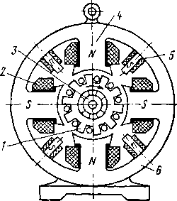
DC machine (Figure 1, A) consists of two main parts:
1) a fixed part, intended mainly to create a magnetic flux;
2) the rotating part, which is called the armature and in which the process of converting mechanical energy into electrical energy (electric generator) or vice versa occurs - electrical energy to mechanical (electric motor). The fixed and rotating parts are separated from each other by a gap.
The fixed part of a DC machine consists of main poles 3(Figure 2), designed to create the main magnetic flux; additional poles 4, installed between the main and employees to achieve spark-free operation brushes 6 on the collector (Figure 1, b); bed 1.
Anchor 7 is a cylindrical body rotating in the space between the poles, and consists of gear armature core; laid on it windings; collector And brush apparatus. IN brush holders 5 are brushes 6, providing sliding contact with the commutator during rotation. On shaft 2 The fan and balancing ring are pressed onto the engine.
Picture 1– DC machine design A and collector b.
Collector assembled from copper plates isolated from each other and from the housing 3. Pressed micanite cuffs are put on the pressure flanges 4. Pressure flanges are insulated from each other with micanite gaskets 2, which are tightened with a ring nut 6. Sections of the armature winding are soldered to the cockerels 7. The commutator is subjected to heat treatment in such a way that it forms monolithic structure, eliminating beats and vibrations.
 Figure 2– Main pole.
Main pole consists of a core (5) assembled on studs made of sheet electrical steel 1 mm thick. On the side facing the armature, the core has a pole piece 6, which serves to facilitate the conduction of magnetic flux through the air gap. A field winding coil 1 is placed on the pole core, through which a direct current passes. The coil is wound onto the frame 2. The poles are fastened to the frame 4 using special bolts 3.
Classification of armature windings of DC machines
Regardless of the type of anchor (ring or drum) we have following types armature windings of DC machines:
a) simple loop; b) simple wave; c) complex loop;
d) complex wave.
Simple windings always form only one system of conductors closed on themselves, while complex windings can form one or several such systems. In the first case, we will call the complex winding once-closed, in the second – multiple closed.
Generator mode.
Let's assume that the machine's anchor (Figure 3, A) is rotated clockwise. Then an EMF is induced in the conductors of the armature winding, the direction of which can be determined by the right-hand rule and is shown in Figure 3, A. Since the flux of poles is assumed to be constant, this emf is induced only due to the rotation of the armature and is called rotational emf.
The magnitude of the EMF induced in the conductor of the armature winding.
 , (1)
, (1)
Figure 3– Simplest work
DC machines in mode
generator ( A) and engine ( b)
where is the magnitude of magnetic induction in the air gap between the pole and the armature at the location of the conductor; – active length of the conductor between the pole and the armature at the location of the conductor, i.e. the length over which it is located in a magnetic field; – linear speed of conductor movement.
Due to symmetry, the same EMF is induced in both conductors, which add up along the contour of the turn, and therefore the total EMF of the armature of the machine in question
![]() . (2)
. (2)
The emf is variable because the conductors of the armature winding pass alternately under the north and south poles, as a result of which the direction of the emf in the conductors changes.
The EMF frequency in a two-pole machine is equal to the armature rotation speed, expressed in revolutions per second:
and in general case when the machine has pairs of poles with alternating polarity,
In a generator, the commutator is a mechanical rectifier that converts the alternating current of the armature winding into direct current in the external circuit.
The DC voltage at the generator armature terminals will be less by the amount of voltage drop in the armature winding resistance:
The conductors of the armature winding with current are in a magnetic field, and therefore electromagnetic forces will act on them:
the direction of which is determined by the left-hand rule.
These forces create a mechanical torque, which is called electromagnetic torque and in Figure 3 A, is equal
![]() , (7)
, (7)
where is the diameter of the anchor. As can be seen from Figure 3 A, in generator mode this moment acts against the direction of rotation of the armature and is braking.
Engine mode.
Considered simplest machine can also operate as a motor if direct current is supplied to the armature winding from external source. In this case, electromagnetic forces will act on the conductors of the armature winding and an electromagnetic torque will arise. The quantities and , as for the generator, are determined by equalities (3.6) and (3.7). With a sufficient value, the armature of the machine will rotate and develop mechanical power. The moment is driving and acts in the direction of rotation.
If we wish that with the same polarity of the poles, the direction of rotation of the generator (Figure 3, A) and engine (Figure 3, b) were the same, then the direction of action , and therefore the direction of current in the engine should be reversed compared to the generator (Figure 3, b).
In motor mode, the commutator converts the direct current consumed from the external circuit into alternating current in the armature winding and thus works as a mechanical current inverter.
The conductors of the motor armature winding also rotate in the magnetic field, and therefore an EMF is also induced in the motor armature winding, the magnitude of which is determined by equality (3.2). The direction of this EMF in the engine (Figure 3, b) is the same as in the generator (Figure 3, A). Thus, in a motor, the armature emf is directed opposite the current and the voltage applied to the armature terminals. Therefore, the EMF of the motor armature is also called counter electromotive force.
The voltage applied to the motor armature is balanced by the emf and the voltage drop in the armature winding:
Reversibility principle:
From the above it follows that each DC machine can operate both in generator mode and in motor mode. This property is inherent in all types of rotating electrical machines and is called reversibility.
To transition a DC machine from generator mode to motor mode and back, with the polarity of the poles and brushes unchanged and the direction of rotation unchanged, only a change in the direction of the current in the armature winding is required.
Therefore, such a transition can be carried out quite simply and in certain conditions even automatically.
Energy conversion.
Figure 4 shows the directions of action of mechanical and electrical quantities in the armature of a generator and a DC motor.

Figure 4– Directions of EMF current and moments in the generator ( A) and engine ( b) direct current.
According to Newton's first law, when applied to a rotating body, the driving and braking torques acting on this body balance each other. Therefore, in a generator under steady-state operating conditions, the electromagnetic torque
![]() , (9)
, (9)
where is the torque on the generator shaft developed by the prime mover, is the moment of friction forces in the bearings, on the air and on the machine commutator, is the braking torque caused by losses due to hysteresis and eddy currents in the armature core.
These power losses result from the rotation of the armature core in the stationary magnetic field of the poles. The electromagnetic forces that arise in this case have a braking effect on the armature and in this respect manifest themselves like friction forces.
In an engine at steady state
![]() , (10)
, (10)
where is the braking torque on the motor shaft developed by the working machine (machine tool, pump, etc.).
In the generator it is the driving moment, and in the engine the braking moment, and in both cases it is opposite in direction.
The power developed by the electromagnetic torque is called electromagnetic power and is equal to
represents angular velocity rotation.
In the armature winding, under the influence of EMF and current, the internal electric power of the armature develops
According to equalities (4.5) and (4.6), i.e. The internal electrical power of the armature is equal to the electromagnetic power developed by the electromagnetic torque, which reflects the process of converting mechanical energy into electrical energy in the generator and the reverse process in the engine.
For generator
![]() (15)
(15)
and for the engine
![]() . (16)
. (16)
The left parts of these expressions represent the electrical power at the armature terminals, the first terms of the right parts are the electromagnetic power of the armature and the last terms are the electrical power losses in the armature.
According to these expressions, the mechanical power developed on the generator shaft by the prime mover, minus mechanical and magnetic losses, is converted into electrical power in the armature winding, and the electrical power minus losses in this winding is supplied to the external circuit. In the engine, the electrical power supplied to the armature from an external circuit is partially spent on losses in the armature winding, and the rest is converted into electromagnetic field power and the latter into mechanical power, which, minus friction losses and losses in the steel of the armature, is transferred to the working machine.
Losses.
General provisions. When an electric machine operates, part of the energy it consumes is wasted and dissipated as heat. The power of lost energy is called power losses or just losses.
Losses in electrical machines are divided into basic and additional. The main losses arise as a result of the main electromagnetic and mechanical processes, and additional losses are caused by various secondary phenomena. In rotating electrical machines, the main losses are divided into 1) mechanical losses, 2) magnetic losses (steel losses) and 3) electrical losses.
Electrical losses include losses in windings, which are also called copper losses, although windings are not always made of copper, losses in control rheostats and losses in the contact resistance of brush contacts.
Mechanical losses consist of 1) losses in bearings, 2) losses due to friction of brushes on the commutator or slip rings, and 3) ventilation losses, which include losses due to friction of machine parts against air and other losses associated with ventilation of the machine.
Losses in bearings depend on the type of bearings (rolling or sliding), the condition of the rubbing surfaces, the type of lubrication, etc.
Brush friction losses can be calculated using the formula
![]() , (17)
, (17)
where is the coefficient of friction of the brushes on the commutator or slip rings ( ![]() ); – specific (per unit area) pressure on the brush; – contact surface of all brushes; – peripheral speed of the commutator or slip rings.
); – specific (per unit area) pressure on the brush; – contact surface of all brushes; – peripheral speed of the commutator or slip rings.
Ventilation losses depend on the design of the machine and the type of ventilation. In self-ventilated machines with a built-in centrifugal fan, ventilation losses are calculated approximately using the formula:
where is the amount of air forced through the machine;
– peripheral speed of the ventilation wings along their outer diameter, .
General mechanical losses
As follows from the above, in any given machine the losses depend only on the rotation speed and do not depend on the load. In DC machines with a power of 10 - 500 kW, losses are about 2 - 0.5% of the rated power of the machine.
Magnetic losses include losses due to hysteresis and eddy currents caused by magnetization reversal of the active steel cores. To calculate these losses, the core is divided into parts, in each of which the magnetic induction is constant. For example, in DC machines the losses in the armature core and in the armature teeth are calculated separately.
Magnetic losses also include additional losses that depend on the magnitude of the main flux of the machine (flux of poles) and are caused by the gear structure of the cores. These losses are also called additional no-load losses, since they exist in an excited machine already at idling. These losses in DC machines include, first of all, surface losses in the pole pieces caused by the serration of the armature.
If there are also grooves in the pole pieces of a DC machine (if there is a compensation winding), then magnetic flux pulsations occur in the armature teeth and poles as a result of their mutual movement. The fluxes in the teeth are maximum when the armature tooth is located opposite the pole tooth, and minimal when the groove is located opposite the tooth. The frequency of these pulsations is also high. In this case, pulsation losses occur in the teeth and surface losses also on the outer surface of the armature.
![]() . (21)
. (21)
Electrical losses also include losses in control rheostats and losses in the transition resistances of brush contacts. The amount of loss in the contact resistance of brush contacts for brushes of the same polarity is calculated by the formula
where is the voltage drop per brush contact.
Additional losses. This group includes losses caused by various secondary phenomena when the machine is loaded.
In DC machines, one part of the losses under consideration arises due to distortion of the magnetic field curve in the air gap under load under the influence of the transverse reaction of the armature. As a result of this, the magnetic flux is distributed unevenly over the teeth and cross-section of the armature back: from one edge of the pole piece, the induction in the teeth and armature back decreases, and from the other edge it increases. Such an uneven distribution of flux causes an increase in magnetic losses, just as an uneven distribution of current in a conductor causes an increase electrical losses. Due to this uneven flux distribution, surface losses in the pole pieces also increase. In the presence of a compensation winding, the considered part of the additional losses is practically absent.
Another part of the additional losses in DC machines is associated with commutation. When the leakage fluxes of the switched sections change over time, eddy currents are induced in the winding conductors. The additional switching current also causes additional losses.
In practice, additional losses are estimated on the basis of experimental data in the form of a certain percentage of the rated power. According to GOST 11828 - 66, these losses for DC machines at rated load are taken: in the absence of a compensation winding, equal to 1.0% and in the presence of a compensation winding, equal to 0.5% of the output power for the generator and the conducted power for the engine. For other loads, these losses are recalculated proportionally to the square of the load current.
All types of additional losses not directly related to electrical processes in the machine winding circuits are covered by mechanical power on the machine shaft.
Total, or total, losses represent the sum of all losses.