Page 2
The current rating of a fuse is the highest current that the fuse can withstand indefinitely. for a long time without collapsing. It is indicated on the fuse insert. But the strength of the melting current of the fuse insert depends on a number of reasons and, first of all, on the duration of the current load and the cooling conditions of the fuse.
For current ratings the following normal scale is adopted: 200, 400, 600, 1000, 1500, 2000, 3000 and 4000 A.
The unit is designed for a rated current of 10 A, a maximum current of 30 A, and its weight is 2 kg. Testing points on the communication cable are placed on cable couplings in increments of 800 - 1000 m, which corresponds to the construction length of the cable. Independent control and measuring points are installed on gas pipelines. The armor and sheath of the cable in the couplings are not bridged, but the conductors are brought out into the instrumentation, which has five terminals, separately from the armor and sheath and marked.
If the generator delivers the rated current and its voltage is at least 12 5 V for 12-volt and 25 V for 24-volt generators, then it should be considered serviceable. In the event of a decrease in current output, close terminals I and Ш of the generator with a conductor; If at the same time the voltage and current of the generator increase, then the relay-regulator should be considered faulty.
V are designed for a rated current of 200 and 400 A, respectively.
Command controllers of the KA-5000 series with a rated current of up to 15 A have up to 12 operating circuits and, in addition to the zero position, seven handle positions in each direction. The handle can be fixed in each position or have a self-return to the zero position.
The motor windings are designed for a certain rated current. As power consumption increases, the current increases. In addition, the current increases when the voltage in the network decreases and when one phase is disconnected. If a phase failure occurs while the compressor is stopped, then when the electric motor is turned on, its power is insufficient to accelerate the compressor. The current in the windings is approximately 4 times the rated value. The engine does not spin up and overheats greatly.
Hello, dear readers and guests of the Electrician's Notes website.
I decided to write an article about calculating the rated current for a three-phase electric motor.
This question is relevant and does not seem so complicated at first glance, but for some reason errors often occur in the calculations.
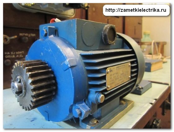
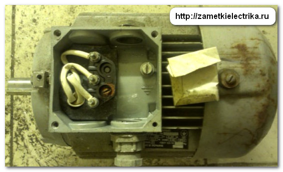
As an example for calculation, I will take a three-phase asynchronous motor AIR71A4 with a power of 0.55 (kW).
Here it is appearance and a technical data label.
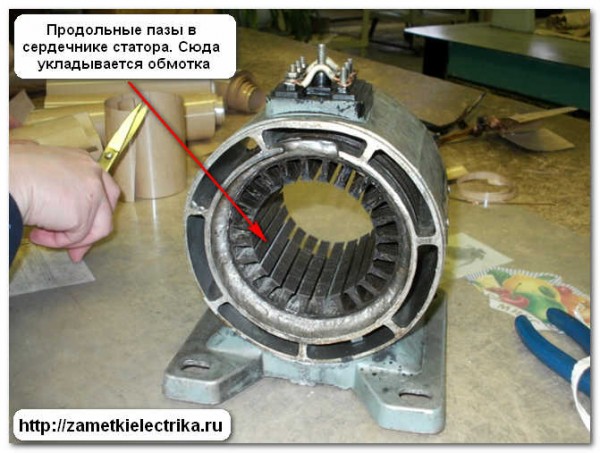
If you plan to connect the engine to three-phase network 380 (V), which means its windings need to be connected in a star circuit, i.e. on the terminal block it is necessary to connect the terminals V2, U2 and W2 to each other using special jumpers.
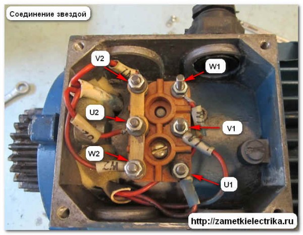
When connecting this motor to a three-phase network with a voltage of 220 (V), its windings must be connected in a triangle, i.e. install three jumpers: U1-W2, V1-U2 and W1-V2.
So let's get started.
Attention! The power on the engine nameplate is not electrical, but mechanical, i.e. useful mechanical power on the motor shaft. This is clearly stated in the current GOST R 52776-2007, clause 5.5.3:

Useful mechanical power denoted as P2.
Even more rarely, the label indicates the power in horsepower(hp), but I have never seen anything like this in my practice. For information: 1 (hp) = 745.7 (Watt).
But we are interested precisely electric power, i.e. power consumed by the motor from the network. Active electrical power is designated as P1 and it will always be greater than mechanical power P2, because it takes into account all engine losses.
1. Mechanical losses (Рmech.)
Mechanical losses include bearing friction and ventilation. Their value directly depends on engine speed, i.e. the higher the speed, the greater the mechanical losses.
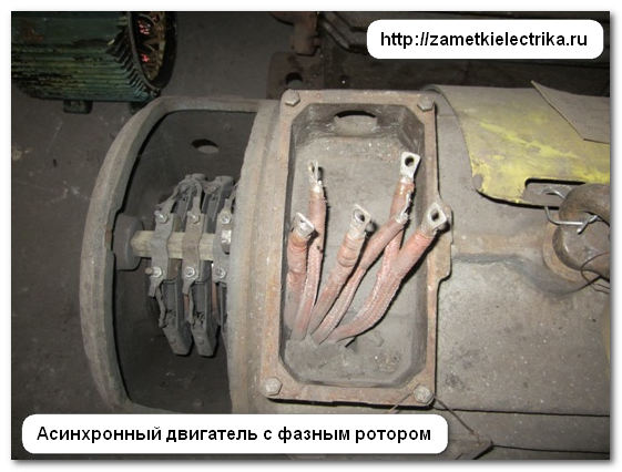
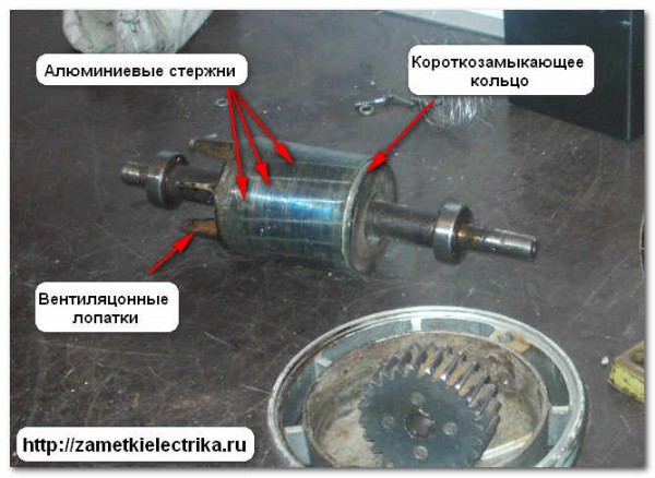
For asynchronous three-phase motors with a wound rotor, losses between brushes and slip rings are also taken into account. More details about the device asynchronous motors You can .
2. Magnetic losses (Рmagn.)
Magnetic losses occur in the “iron” of the magnetic circuit. These include losses due to hysteresis and eddy currents during magnetization reversal of the core.
The magnitude of magnetic losses in the stator depends on the frequency of magnetization reversal of its core. The frequency is always constant and is 50 (Hz).
Magnetic losses in the rotor depend on the frequency of magnetization reversal of the rotor. This frequency is 2-4 (Hz) and directly depends on the amount of motor slip. But magnetic losses in the rotor are small, so they are most often not taken into account in calculations.
3. Electrical losses in stator winding(Re1)
Electrical losses in the stator winding are caused by their heating from the currents passing through them. The higher the current, the more the motor is loaded, the more electrical losses- everything is logical.
4. Electrical losses in the rotor (Re2)
Electrical losses in the rotor are similar to those in the stator winding.
5. Other additional losses (Radd.)
Additional losses include higher harmonics of the magnetomotive force, pulsation of magnetic induction in the teeth, etc. These losses are very difficult to take into account, so they are usually taken as 0.5% of the consumed active power P1.
You all know what's in the engine Electric Energy transforms into mechanical. To explain in a little more detail, when electrical active power P1 is supplied to the motor, some of it is spent on electrical losses in the stator winding and magnetic losses in the magnetic core. The residual electromagnetic power is then transferred to the rotor, where it is consumed by electrical losses in the rotor and converted into mechanical power. Part of the mechanical power is reduced due to mechanical and additional losses. As a result, the remaining mechanical power is useful power P2 on the motor shaft.
All these losses are included in a single parameter - the coefficient useful action(efficiency) of the engine, which is denoted by the symbol “η” and is determined by the formula:
By the way, the efficiency is approximately equal to 0.75-0.88 for engines with power up to 10 (kW) and 0.9-0.94 for engines over 10 (kW).
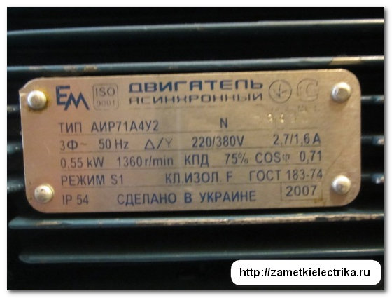
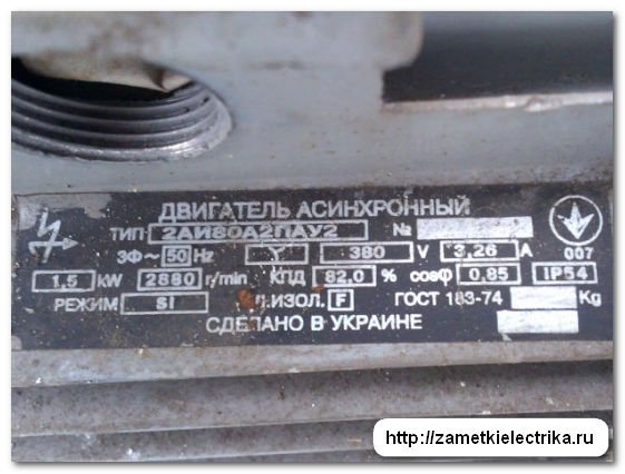
Let us once again turn to the data of the AIR71A4 engine discussed in this article.
Its nameplate contains the following information:
- engine type AIR71A4
- serial number No. ХХХХХ
- type of current - alternating
- number of phases - three-phase
- supply frequency 50 (Hz)
- winding connection diagram ∆/Y
- Rated voltage 220/380 (V)
- rated current at delta 2.7 (A) / at star 1.6 (A)
- rated useful shaft power P2 = 0.55 (kW) = 550 (W)
- rotation speed 1360 (rpm)
- Efficiency 75% (η = 0.75)
- power factor cosφ = 0.71
- operating mode S1
- insulation class F
- protection class IP54
- name of the company and country of manufacture
- year of manufacture 2007
Calculation of the rated current of the electric motor
First of all, it is necessary to find the electrical active power consumption P1 from the network using the formula:
P1 = P2/η = 550/0.75 = 733.33 (W)
Power values are substituted into the formulas in watts, and voltage in volts. Efficiency (η) and power factor (cosφ) are dimensionless quantities.
But this is not enough, because we did not take into account the power factor (cosφ ) , but the motor is an active-inductive load, so to determine the total power consumption of the motor from the network, we use the formula:
S = P1/cosφ = 733.33/0.71 = 1032.85 (VA)
Let's find the rated current of the motor when connecting the windings in a star:
Inom = S/(1.73 U) = 1032.85/(1.73 380) = 1.57 (A)
Let's find the rated current of the motor when connecting the windings in a triangle:
Inom = S/(1.73 U) = 1032.85/(1.73 220) = 2.71 (A)
As you can see, the resulting values are equal to the currents indicated on the motor tag.
To simplify, the above formulas can be combined into one general one. The result will be:
Inom = P2/(1.73 U cosφ η)
Therefore, in order to determine the rated current of the motor, it is necessary to substitute the mechanical power P2 taken from the tag into this formula, taking into account the efficiency and power factor (cosφ), which are indicated on the same tag or in the passport for the electric motor.
Let's recheck the formula.
Motor current when connecting the windings in a star:
Inom = P2/(1.73 U cosφ η) = 550/(1.73 380 0.71 0.75) = 1.57 (A)
Motor current when connecting the windings in a triangle:
Inom = P2/(1.73 U cosφ η) = 550/(1.73 220 0.71 0.75) = 2.71 (A)
I hope everything is clear.
Examples
I decided to give a few more examples with different types of engines and powers. Let's calculate their rated currents and compare them with the currents indicated on their labels.
As you can see, this motor can only be connected to a three-phase network with a voltage of 380 (V), because its windings are assembled into a star inside the motor, and only three ends are brought out into the terminal block, therefore:
Inom = P2/(1.73 U cosφ η) = 1500/(1.73 380 0.85 0.82) = 3.27 (A)
The resulting current of 3.27(A) corresponds to the rated current of 3.26(A) indicated on the tag.
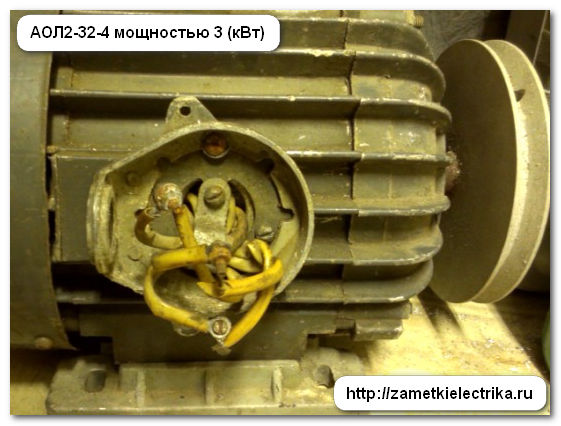
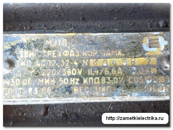
This motor can be connected to a three-phase network with a voltage of both 380 (V) star and 220 (V) delta, because It has 6 ends connected to the terminal block:
Inom = P2/(1.73 U cosφ η) = 3000/(1.73 380 0.83 0.83) = 6.62 (A) - star
Inom = P2/(1.73 U cosφ η) = 3000/(1.73 220 0.83 0.83) = 11.44 (A) - triangle
The obtained current values for different winding connection schemes correspond to the rated currents indicated on the label.
3. AIRS100A4 asynchronous motor with a power of 4.25 (kW)
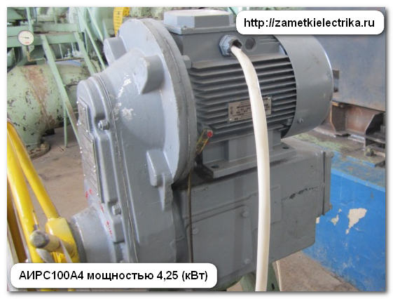
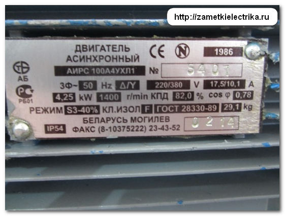
Similar to the previous one.
Inom = P2/(1.73 U cosφ η) = 4250/(1.73 380 0.78 0.82) = 10.1 (A) - star
Inom = P2/(1.73 U cosφ η) = 4250/(1.73 220 0.78 0.82) = 17.45 (A) - triangle
The calculated current values for different winding connection schemes correspond to the rated currents indicated on the motor nameplate.
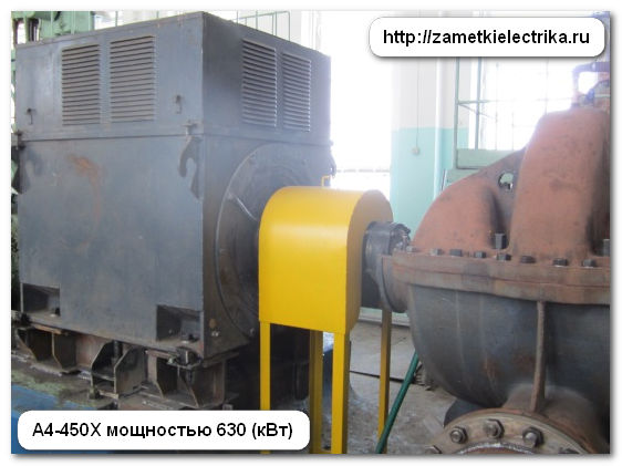
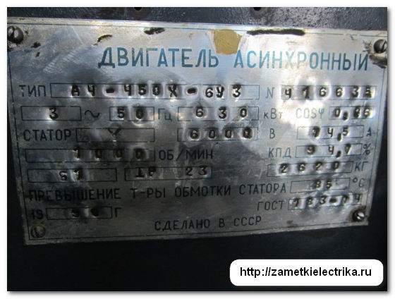
This motor can only be connected to a three-phase network with a voltage of 6 (kV). The connection diagram of its windings is a star.
Inom = P2/(1.73 U cosφ η) = 630000/(1.73 6000 0.86 0.947) = 74.52 (A)
The rated current of 74.52(A) corresponds to the rated current of 74.5(A) listed on the tag.
Addition
The formulas presented above are of course good and according to them the calculation is more accurate, but among the common people there is a more simplified and approximate formula for calculating the rated current of the motor, which is most widespread among home craftsmen and craftsmen.
It's simple. Take the engine power in kilowatts indicated on the tag and multiply it by 2 - here is the finished result. Only this identity is relevant for 380 (V) engines assembled into a star. You can check and increase the power of the above engines. But personally, I insist that you use more accurate calculation methods.
P.S. But now, as we have already decided on the currents, we can begin to select a circuit breaker, fuses, thermal protection of the motor and contactors for its control. I will tell you about this in my next publications. In order not to miss the release of new articles, subscribe to the newsletter of the Electrician's Notes website. Until next time.
To provide reliable protection cable using a circuit breaker, you need to take into account some of the operating features of this device and carry out correct selection. The fact is that the current (I n), which is indicated in the marking of the machine, is actually the operating current, and its excess in a certain range does not cause an immediate shutdown of the network.
Ratings of machines for protecting electrical cables
For example, if the marking is C25, then this means that a current of 25A can flow through this circuit unlimited time. If the excess is up to 13% (28.5A), then a shutdown may occur after more than an hour of operation, up to 45% (36.25A) - in less than an hour. For guaranteed protection network, it is important that the increased current does not exceed the permissible current in the cable.
Such an algorithm for the operation of the machine, on the one hand, will reduce the likelihood of false positives, but on the other hand, it requires a more thoughtful approach to the choice of machine.
Choosing the right circuit breaker is not an easy task, but its solution depends on safe operation houses or apartments and reducing material costs.
Options
Rated current (I n)
Automatic switches have a standardized range of rated currents, this is reflected in GOST R 50345–99, the data is summarized in a table. These are long-term currents flowing through the machine and not causing it to shut down. Using the table, you can select the rated current of the circuit breaker. It contains standard series rated currents (I n) for automatic machines used in Russia.
Standardized range of rated currents (In) for automatic machines
| Rated current A | |||||||||
|---|---|---|---|---|---|---|---|---|---|
| 0.5 | 1 | 1.6 | 2 | 2.5 | 3 | 4 | 5 | 6.3 (or 6) | |
| 8 | 10 | 16 | 25 | 31.5 (or 32) | 40 | 50 | 63 | ||
| 80 | 100 | 125 | 160 | 200 | 250 | 320 | 400 | 500 | 630 |
| 800 | 1000 | 1600 | 2000 | 2500 | 4000 | 5000 | 6300 |
However, the shutdown time is affected by temperature environment and method of mounting the switch. Thus, an increase in air temperature at the location where the machine is installed shortens this period, while a decrease lengthens it. Single installed switch has more a long period, and the one installed in the group is reduced due to the influence of neighboring machines.
The table below provides information on currents leading to long-term tripping and will allow you to select the required rating.
These are normalized currents according to GOST.
| Standardized currents according to GOST for choosing the rating of the machine Character ristics triggered- vending machines type | B, C, D | ||||||||
|---|---|---|---|---|---|---|---|---|---|
| Machine denomination | 6A | 10A | 13A | 16A | 20A | 25A | 32A | 40A | |
| 50A Turn off reading NOT EARLIER, | than 1 hour (1.13*In) | 6.78 A | 11.3 A | 14.69 A | 18.08 A | 22.6 A | 28.25 A | 36.16 A | 45.2 A |
| 50A Turn off 56.5 A NOT MORE, | than 1 hour (1.45*In) | 8.7 A | 14.5 A | 18.85 A | 23.2 A | 29 A | 36.25 A | 46.4 A | 58 A |
72.5 A Using the table below, you can select a circuit breaker based on the shutdown current. For example, it is known that the cable in open wiring
with a copper conductor cross-section of 4 mm 2 has a permissible current of 30A (t. 1.3.4-1.3.8. PUE). We find in the table the nearest lower shutdown current, this is 29A, which means we need a C20 circuit breaker. If you choose a machine with a rated current of C25, then the long-term flowing current in the cable will be 36.25A; the machine’s shutdown time can reach 1 hour. During this time, the cable can heat up to a significant temperature, which will cause the insulation to melt. If a repetition of such a situation is not excluded, it will certainly lead to an accident.
It is also impossible without complex measurements to accurately determine at what load current this or that particular instance will operate, but there is a corridor in which any instance of this rating is guaranteed to operate.
Time-current characteristics
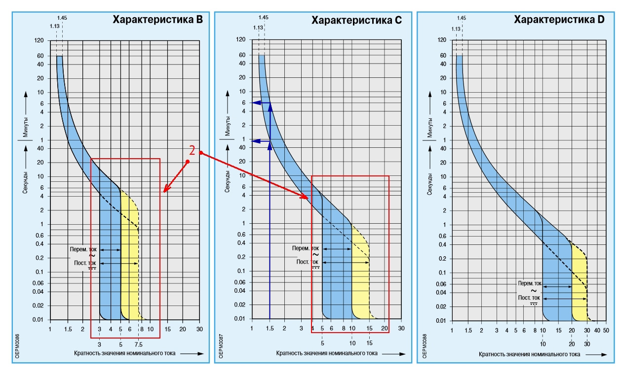
These characteristics are presented in the form of a graph, from which you can quite accurately determine the current and time when the device is guaranteed to turn off.
For example, you can find out after what period of time a type C machine will turn off if a current flows through it one and a half times more than the rated current, i.e. I/I n = 1.5. We draw a vertical line on the graph so that it intersects the range of values and from the points of intersection of this line with the blue zone we draw horizontal lines to the Y axis.
On the Y axis we see the time: minimum - 50 seconds, maximum - around 6 minutes. This means that with double the current, this cable will operate under such a load for up to 6 minutes.
To determine the breaking currents for other types, B or D, horizontal lines should be drawn to the Y axis from the corresponding areas.
In the event of a short circuit, the machines operate very reliably, turning off the network in less than 0.1 seconds; during such a period of time the cable does not have time to noticeably heat up.
If it happened emergency shutdown, do not rush to turn on the machine, first turn off powerful appliances, especially heating ones: iron, boiler, electric stove, microwave, etc. Turn on the machine after 5-10 minutes; if a repeated shutdown occurs, it is better to call a specialist.
Cables GOST 31996–2012
When choosing a machine, it is necessary to take into account the characteristics of the cables. The most important is the permissible current (I add). It shows at what maximum current the cable can operate throughout its entire service life. This table from the PUE contains information about permissible cable currents depending on the material and conditions of cable laying.
Permissible currents for cable depending on materials
| Open wiring | Seche- tion cable la, mm2 | Closed wiring | ||||||||||
|---|---|---|---|---|---|---|---|---|---|---|---|---|
| Copper | Aluminum | Copper | Aluminum | |||||||||
| Current A | Power- ness, kW | Current A | Power- ness, kW | Current A | Power- ness, kW | Current A | Power- ness, kW |
|||||
| 220 V | 380 V | 220 V | 380 V | 220 V | 380 V | 220 V | 380 V | |||||
| 11 | 2.4 | - | - | - | - | 0.5 | - | - | - | - | - | - |
| 15 | 3.3 | - | - | - | - | 0.75 | - | - | - | - | - | - |
| 17 | 3.7 | 6.4 | - | - | - | 1 | 14 | 3 | 5.3 | - | - | - |
| 23 | 5 | 8.7 | - | - | - | 1.5 | 15 | 3.3 | 5.7 | - | - | - |
| 26 | 5.7 | 9.8 | 21 | 4.6 | 7.9 | 2 | 19 | 4.1 | 7.2 | 14 | 3 | 5.3 |
| 30 | 6.6 | 11 | 24 | 5.2 | 9.1 | 2.5 | 21 | 4.6 | 7.9 | 16 | 3.5 | 6 |
| 41 | 9 | 15 | 32 | 7 | 12 | 4 | 27 | 5.9 | 10 | 21 | 4.6 | 7.9 |
| 50 | 11 | 19 | 39 | 8.5 | 14 | 6 | 34 | 7.4 | 12 | 26 | 5.7 | 9.8 |
| 80 | 17 | 30 | 60 | 13 | 22 | 10 | 50 | 11 | 19 | 38 | 8.3 | 14 |
| 100 | 22 | 38 | 75 | 16 | 28 | 16 | 80 | 17 | 30 | 55 | 12 | 20 |
| 140 | 30 | 53 | 105 | 23 | 39 | 25 | 100 | 22 | 38 | 65 | 14 | 24 |
| 170 | 37 | 64 | 130 | 28 | 49 | 35 | 130 | 29 | 51 | 75 | 16 | 28 |
From this table you can find the required cable cross-section and permissible current depending on the wiring conditions, open or buried. For example, the power of all appliances in the apartment is 9 kW. For open single-phase copper wiring, the wire cross-section is 4 mm 2, current 41A, for closed - the nearest higher value power 11 kW, cross-section 10 mm 2, current 50A. The nearest lower rating of the circuit breaker is 32A.
If there is doubt about the quality of the electrical wiring, then it is better to exercise caution and choose a machine with a rating lower than the value in the table.
The residential network has a branched structure: a current of different strength will flow in each branch, so the wires have different cross-sections. If you install one circuit breaker only at the entrance, it will not be able to protect individual sections of the wiring from overload. If the entire network is laid with a cable of the same cross-section, then this is an unjustified financial expense. The best solution would be to install the appropriate current on each section of the machine. The figure shows an approximate structure.
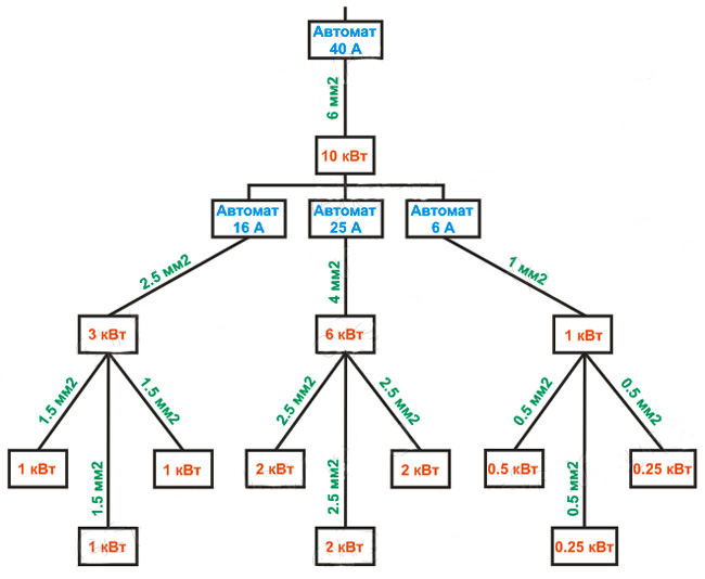
Installation of machines for the appropriate current
The figure clearly shows the load on each section and the cross-section of the wire. By installing the appropriate machines, you can reliably protect the entire network from short circuit or overload. In addition, at any time it is possible to select and disable one or another section, maintaining the functionality of the rest of the network.
When using powerful asynchronous motors in everyday life, especially 3-phase ones, for example, power tools, it is advisable to turn them on through a separate circuit breaker, since they have a large starting current, and when operating through a common circuit breaker, a power outage may occur even during normal operation of the equipment.
Selection of section. Video
You can learn in detail about the choice of cable cross-section and machine rating from this video.
If the selection of a circuit breaker is carried out for an existing network, then first of all you need to know the cross-section of the wiring, and then make a choice based on it. If the network has not yet been laid, then you need to start by calculating the possible load, taking into account all household appliances that are planned to be connected. Wiring serves for correct operation 20-30 years, during this time, most likely, new devices will appear in everyday life, so a power reserve of 20 percent should be provided.
The explanatory dictionary of the Russian language by Academician Ozhegov explains the meaning of the word “nominal”, as designated, called, but not fulfilling its duties, purposes, that is, fictitious.
This definition quite accurately explains the electrical terms of rated voltage, current and power. They seem to be there, assigned and defined, but in fact they only serve as guidelines for electricians. The actual numerical expressions of these parameters in reality differ from the assigned values.
For example, we are all familiar with the variable single-phase network with a voltage of 220 volts, which is considered nominal. In fact, its value according to GOST can only reach the upper limit of 252 volts. This is how the state standard works.
The same picture can be seen with the rated current.
Principle of determining the rated current
The basis for choosing its value is the maximum possible thermal heating electrical conductors, including their insulation, which must operate reliably under load indefinitely.
At rated current, a thermal balance is maintained between:
heating of conductors due to temperature effects electric charges, described by the action of the Joule-Lenz law;
cooling due to the removal of part of the heat to the environment.
In this case, heat Q1 should not affect the mechanical and strength characteristics of the metal, and heat Q2 should not affect the change in the chemical and dielectric properties of the insulation layer.
Even if the rated current value is slightly exceeded, after a certain period of time it will be necessary to remove the voltage from the electrical equipment to cool the metal of the current conductor and insulation. Otherwise, their electrical properties will be disrupted and breakdown of the dielectric layer or metal deformation will occur.
Any electrical equipment (including current sources, its consumers, connecting wires and systems, protective devices) is calculated, designed and manufactured to operate at a certain rated current.
Its value is indicated not only in the technical factory documentation, but also on the housing or nameplates of electrical equipment.
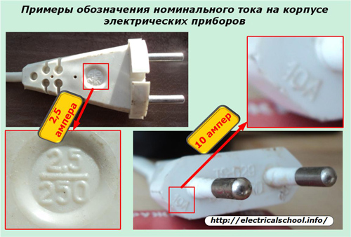
The above photograph clearly shows the rated current values of 2.5 and 10 amperes, which are made by stamping during the manufacture of an electrical plug.
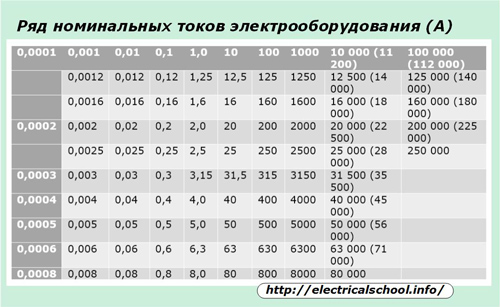
In order to standardize equipment, GOST 6827-76 introduced a number of rated current values at which almost all electrical installations must operate.
How to select a protective device based on rated current
Since the rated current determines the possibility of long-term operation of electrical equipment without any damage, all current protective devices are configured to operate when it is exceeded.
In practice, situations quite often occur when a power supply overload occurs for a short period of time. various reasons. In this case, the temperature of the metal conductor and the insulation layer do not have time to reach the limit when a violation of their electrical properties occurs.
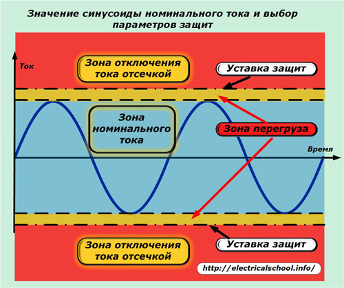
For these reasons, the transfer zone is allocated to separate area, which is limited not only by the magnitude, but also by the duration of action. When the critical temperature values of the insulation layer and metal conductor are reached, the voltage from the electrical installation must be removed to cool it.
These functions are performed by overload protection operating on a thermal principle:
circuit breakers;
thermal releases.
They perceive thermal load and are configured to turn it off with a certain time delay. The setting of the protections that perform “instantaneous” load cutoff lies slightly above the overload current. The term "instantaneous" actually defines action in the shortest possible period of time. For today's fastest current protection cutoff is completed in just under 0.02 seconds.
The operating current in normal power mode is most often less than the nominal value.
In the example given, the case for circuits is analyzed alternating current. In chains DC voltage fundamental difference There is no relationship between the operating, rated current and the choice of settings for the operation of protections.
How is the circuit breaker configured to operate at rated current?
In defense industrial devices and household electrical networks, the most widely used circuit breakers are those that combine in their design:
thermal releases operating with a time delay;
current cut-off, which very quickly turns off the emergency mode.
In this case, circuit breakers are manufactured for rated voltage and current. Based on their size, protective devices are selected for operation in the specific conditions of a certain circuit.
For this purpose, the standards define 4 types of time-current characteristics for different designs machine guns They are designated by the Latin letters A, B, C, D and are designed to guarantee the shutdown of accidents with a rated current ratio of 1.3 to 14.
Based on the time-current characteristic, taking into account the ambient temperature, the circuit breaker is selected for a certain type of load, for example:
semiconductor devices;
lighting systems;
schemes with mixed loads and moderate starting currents;
chains with high overload capacity.
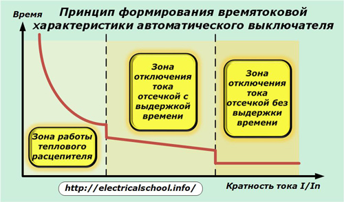
The time-current characteristic can consist of three action zones, as shown in the picture, or two (without the middle one).
The designation of the rated current can be found on the body of the machine. The picture shows a switch with a value of 100 amperes indicated.
This means that it will work (turn off) not from the rated current (100 A), but from its excess. Let’s say that if the cutoff of the machine is set to a multiple of 3.5, then a current of 100x3.5 = 350 amperes or more will be stopped by it without a time delay.
When the thermal release is set to a multiple of 1.25, then when the value reaches 100x1.25 = 125 amperes, the shutdown will occur after some time, for example, one hour. In this case, the circuit will work with overload during this period.
It should be taken into account that the time the machine is turned off is also influenced by other factors related to maintaining temperature regime protection:
environmental conditions;
filling degree distribution panel equipment;
possibility of heating or cooling from external sources.
How to select electrical wiring and circuit breaker based on rated current
To determine the basic electrical parameters of protections and wires in mandatory the load applied to them is taken into account. To do this, it is calculated based on the rated power of the devices connected to the operation, taking into account their occupancy factor.
For example, the socket group located in the kitchen is connected to work Dishwasher, multicooker, electric oven and microwave oven that consume total power in normal mode 5660 watts (taking into account the frequency of switching on).
Rated voltage household network 220 volt. Let's determine the load current that will pass through the wires and protective devices by dividing the power by the voltage. I=5660/220=25.7 A.
Next, look at the table of a number of rated currents for electrical equipment. There is no automatic switch for this current. But, manufacturers produce 25 amp circuit breakers. Its value most closely matches our objectives. That's why we choose it as a basis. protective device for electrical wiring of consumers of the socket group.
After this, we need to decide on the wire material and cross-section. Let's take copper as a basis, because aluminum wiring even for domestic purposes it is no longer popular due to its performance characteristics.
Electricians' reference books provide tables for selecting wires from different materials by current load. Let's take our case, taking into account the fact that the wiring is carried out with a separate cable with polyethylene insulation, hidden in the wall groove. We will accept temperature limits corresponding to room conditions.
The table will provide us with information that the minimum permissible cross-section of a standard copper wire for our case - 4 mm square. You can’t take less, but it’s better to increase it.
Sometimes the task arises of selecting the protection rating for already working wiring. In this case, it is quite justified to determine the load current of the consumer network with an electrical measuring instrument and compare it with that calculated by the above theoretical method.
In this way, the term "current rating" helps electricians navigate technical specifications electrical equipment.
In the previous series of articles, we studied in detail the purpose, design and principle of operation of a circuit breaker, analyzed its main characteristics and connection diagrams, now, using this knowledge, we will come to the issue of choice circuit breakers. In this post we will look at, how to calculate the rated current of a circuit breaker.
This article continues the series of publications. In the following publications I plan to analyze in detail how to choose a cable cross-section, consider the calculation of the electrical wiring of an apartment for specific example with calculation of cable cross-section, selection of ratings and types of machines, breakdown of wiring into groups. At the end of the series of articles on circuit breakers there will be a detailed step-by-step comprehensive algorithm for their selection.
Do you want to not miss the release of these materials? Then subscribe to the site news, the subscription form is on the right and at the end of this article.
So let's get started.
Electrical wiring in an apartment or house is usually divided into several groups.
The group line feeds several consumers of the same type and has a common protection device. In other words, these are several consumers that are connected in parallel to one power cable from and a common circuit breaker is installed for these consumers.
Each group is posted electric cable of a certain cross-section and is protected by a separate circuit breaker.
To calculate the rated current of the machine, it is necessary to know the maximum operating current of the line, which is allowed for its normal and safe operation.
The maximum current that a cable can withstand without overheating depends on the cross-sectional area and material of the cable conductor (copper or aluminum), as well as on the method of wiring (open or hidden).
It is also necessary to remember that the circuit breaker serves to protect electrical wiring from overcurrents, and not electrical appliances. That is, the machine protects the cable that is laid in the wall from the machine in electrical panel to the outlet, not the TV, electric stove, iron or washing machine that are connected to this outlet.
Therefore, the rated current of the circuit breaker is selected, first of all, based on the cross-section of the cable used, and then the connected electrical load is taken into account. The rated current of the machine must be less than the maximum permissible current for a cable of a given section and material.
The calculation for a group of consumers differs from the calculation of a single consumer network.
Let's start with the calculation for a single consumer.
1.A. Calculation of current load for a single consumer
In the passport for the device (or on the plate on the case), we look at its power consumption and determine rated current:
In an AC circuit there are two different types resistance – active and reactive. Therefore, the load power is characterized by two parameters: active power and reactive power.
Power factor cos φ characterizes the amount of reactive energy consumed by the device. Most household and office equipment has an active load nature (they have no or low reactance), for them cos φ = 1.
Refrigerators, air conditioners, electric motors (e.g. submersible pump), fluorescent lamps, etc., along with the active component, also have a reactive component, so for them it is necessary to take into account cos φ.
1.B. Calculation of current load for a group of consumers
The total load power of a group line is determined as the sum of the powers of all consumers in a given group.
That is, to calculate the power of a group line, you need to add up the powers of all devices in this group (all devices that you plan to turn on in this group).
We take a sheet of paper and write down all the devices that we plan to connect to this group (i.e. to this wire): iron, hair dryer, TV, DVD player, table lamp etc.):
When calculating a group of consumers, the so-called demand factor KS, which determines the probability of simultaneous switching on of all consumers in a group over a long period of time. If all electrical appliances in a group operate simultaneously, then Kc = 1.
In practice, usually all devices do not turn on at the same time. In general calculations for residential premises, the demand coefficient is taken depending on the number of consumers from the table shown in the figure.
The power of consumers is indicated on the plates of electrical appliances, in their passports; in the absence of data, you can take it according to the table (RM-2696-01, Appendix 7.2), or look at similar consumers on the Internet:
Based on the calculated power, we determine the total design power: We determine the calculated load current for a group of consumers:
The current calculated using the above formulas is obtained in amperes.
2. Select the rating of the circuit breaker.
For internal power supply residential apartments and houses mainly use modular circuit breakers.
We select the rated current of the machine equal to the design current or the nearest larger one from the standard range:
6, 10, 16, 20, 25, 32, 40, 50, 63 A.
If you choose a smaller circuit breaker, then the circuit breaker may trip at full load in the line.
If the selected rated current of the machine is greater than the maximum possible current of the machine for a given cable cross-section, then it is necessary to select a cable of a larger cross-section, which is not always possible, or such a line must be divided into two (if necessary, more) parts, and conduct the entire above calculation first.
It must be remembered that for the lighting circuit of home wiring, cables of 3 × 1.5 mm 2 are used, and for the socket circuit - with a cross section of 3 × 2.5 mm 2. This automatically means limiting the power consumption for the load supplied through such cables.
It also follows from this that circuit breakers with a rated current of more than 10A cannot be used for lighting lines, and for socket lines - more than 16A. Light switches are produced on maximum current 10A, and sockets for a maximum current of 16A.
I recommend materials