Hello dear friends! In this article, you will learn what is current short circuit, its causes and how to calculate it. A short circuit occurs when current-carrying parts of different potentials or phases are connected to each other. A short circuit can also form on the equipment case that is connected to the ground. This phenomenon is also typical for electrical networks and electrical receivers.
Causes and effects of short circuit current
The causes of a short circuit can be very different. This is facilitated by wet or aggressive environment, in which the insulation resistance deteriorates significantly. A closure can result mechanical influences or human error during repairs and maintenance. The essence of the phenomenon lies in its name and is a shortening of the path along which the current passes. As a result, current flows past the resistive load. At the same time, it increases to unacceptable limits if the protective shutdown does not work.
Short-circuit currents have an electrodynamic and thermal effect on equipment and electrical installations, which ultimately leads to their significant deformation and overheating. In this regard, it is necessary to pre-calculate the short-circuit currents.
How to calculate short circuit current at home
Knowledge of the magnitude of the short circuit current is essential to ensure fire safety. Obviously, if the measured short circuit current is less than the set current maximum protection circuit breaker or 4 times the fuse current rating, then the response time (fusible link burnout) will be longer, and this, in turn, can lead to excessive heating of the wires and their ignition.
How can this current be determined? Exist special techniques and special devices for this. Here we consider the question of how to do this, having only or even a voltmeter. It is obvious that this method has not very high accuracy, but still sufficient to detect the discrepancy between the overcurrent protection and the value of this current.
How to do it at home? It is necessary to take a sufficiently powerful receiver, for example, Electric kettle or iron. It would be nice to have a trio. We connect our consumer and a voltmeter or multimeter to the tee in voltage measurement mode. We write down the steady value of the voltage (U1). We turn off the consumer, and record the voltage without load (U2). Next, we make a calculation. You need to divide the power of your consumer (P) by the difference in the measured voltages.
Ic.c.(1) = Р/(U2 – U1)
Let's count on an example. Kettle 2 kW. The first measurement is 215 V, the second measurement is 230 V. According to the calculation, it turns out 133.3 A. If, for example, there is a VA 47-29 machine with characteristic C, then its setting will be from 80 to 160 Amperes. Therefore, it is possible that this machine will work with a delay. According to the characteristics of the machine, it can be determined that the response time can be up to 5 seconds. Which is basically dangerous.
What to do? It is necessary to increase the magnitude of the short circuit current. You can increase this current by replacing the wires of the supply line with a larger cross section.
Useful short circuit
It would seem that the obvious fact is that a short circuit is an extremely bad, unpleasant and undesirable phenomenon. It may lead to best case to de-energize the facility, turn off emergency protective equipment, and at worst - to burn out the wiring and even fire. Therefore, all efforts must be focused on avoiding this scourge. However, the calculation of short-circuit currents has a very real and practical meaning. A lot has been invented technical means operating in the mode of high current values. An example is the usual welding machine, especially arc, which at the time of operation almost short-circuits the electrode with grounding. Another issue is that these regimes are of a short-term nature, and the power of the transformer makes it possible to withstand these overloads. When welding at the point of contact of the end of the electrode, huge currents pass (they are measured in tens of amperes), as a result of which enough heat is released to locally melt the metal and create a strong seam.
Topic: what is a short circuit in an electrical circuit, what are the consequences of a short circuit.
Many have heard about an electrical short circuit, but not everyone knows the essence of this phenomenon. Let's deal with this. So, if you delve into the very phrase “short circuit”, then you can understand that some kind of process is taking place in which something closes along a short, namely the shortest path of flow electric current (electric charges in the conductor). Simply put, there is a path through which electricity flows, its current of charges. These are various electrical circuits, conductors of electricity. The longer this path, the more obstacles the charges need to overcome, the more electrical resistance this path. And from Ohm's law, we know what more resistance chains, topics less power current will be in it (at a certain voltage value). Therefore, on the shortest path, there will be the maximum possible current, and this path will be short if the ends of the power source itself are shorted.
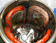
In general, we have, for example, the usual car battery(when charged). If you connect a light bulb designed for battery voltage (12 volts) to it, then as a result of the passage of a current of a certain value through this lamp, we will receive light and heat radiation. The lamp has a certain electrical resistance, which limits the current flowing through this circuit. To intentionally short circuit, we just need to take a piece of wire and connect it to the ends of the battery leads (parallel to the lamp). This wire has very little resistance compared to a lamp. Therefore, there is no special restriction that would prevent the movement of charged particles. And as soon as we close such a circuit, we get our short circuit. A large current will immediately flow through the wire, which can simply heat and melt this piece of wire.
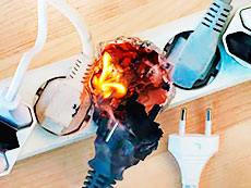 As a result of such a short circuit, the conductor (its insulation) will ignite, up to a fire, if this conductor, by its ignition, transfers fire to flammable things that are nearby. In addition, such a sharp, spasmodic current flow can be harmful to the battery itself. It also starts to heat up at this time. And as you know, batteries really do not like excessive heat. At a minimum, their service life is significantly reduced after this, and as a maximum, they fail and even catch fire and explode. If such a short circuit occurs, for example, with a lithium battery in a phone (which has no electronic protection inside), strong heating occurs for several seconds, then a flame and an explosion form.
There are some batteries that are originally designed to deliver high currents (traction batteries), but even with them a complete short circuit can lead to big trouble. Well, what happens to the voltage during a short circuit? From school physics it should be known that the greater the current, the greater the voltage drop in this section of the circuit. Therefore, when no load is connected to the power supply, you can see the maximum voltage value on it (this is source emf supply, its electromotive force). As soon as we load this power supply, a certain voltage drop immediately appears. And the greater the load, the greater the voltage drop. Since, in the event of a short circuit, the resistance of the circuit is practically zero, and the current strength will be the maximum possible, the voltage drop across the power source will also be maximum (near zero).
 This we considered the option of a complete short circuit, which occurs directly at the terminals of the power source. Yes, here's what else to add about it. In the case of a battery, there will be a large current load on the internal parts and chemical substances the battery itself (electrolyte, plates, leads). In the event of a short circuit on such power sources as electric generators, the current load falls on the windings of these generators, which leads to its excessive heating and damage (well, those circuits that operate in the generator after this winding). A short circuit at the terminals of various power supplies leads to overheating and failure of the electrical circuits current sources and the secondary winding of the transformer.
A short circuit may occur in the electrical circuit wiring diagrams. In this case, the consequences are also extremely negative. But at the same time, the current strength will already be, as a rule, slightly less than in the case of a short circuit at the output of the power source. For example, there is a sound amplifier circuit. Suddenly, due to poor insulation of the speakers themselves, a short circuit occurs at the sound output of this amplifier. As a result, the output transistors, the microcircuit in the last stages of sound amplification, will most likely burn out. The power supply itself in this case may not even be affected, since an excessive current load may not reach it. I think you got the point of the short circuit.
P.S. In any case, the phenomenon of an electrical short circuit leads to disastrous consequences. Normal fuses, circuit breakers, protection circuits, etc. are usually used to protect against this. Their task is to quickly break the electrical circuit with a sharp increase in current strength. That is, an ordinary fuse is, as it were, the weakest link in all electrical circuits. As soon as the current strength has increased sharply, the fusible link simply melts and breaks the circuit. This in most cases results in other circuits in the circuit remaining undamaged.
Hello, dear readers and visitors of the Electrician's Notes website.
I have an article on my site about . I cited cases from my practice in it.
So, in order to minimize the consequences of such accidents and incidents, it is necessary to choose the right electrical equipment. But in order to choose it correctly, you need to be able to calculate the short-circuit currents.
In today's article, I will show you how you can independently calculate the short circuit current, or short circuit current for short, using a real example.
I understand that many of you do not need to make calculations, because. Usually this is done either by designers in organizations (firms) that have a license, or by students who write the next course or diploma project. I especially understand the latter, because being a student himself (back in the year 2000), he was very sorry that there were no such sites on the network. Also, this publication will be useful for power engineers and to raise the level of self-development, or to refresh the memory of the once past material.
By the way, I already brought . If you are interested, please follow the link and read.
So, let's get down to business. A few days ago, we had a fire at our enterprise. cable route near workshop assembly No. 10. The cable tray burned out almost completely with all the power and control cables going there. Here is a photo from the scene.


I won’t go into the “debriefing” much, but my management had a question about the operation of the introductory circuit breaker and its correspondence to the protected line. In simple words I will say that they were interested in the magnitude of the short circuit current at the end of the input power cable line, i.e. in the place where the fire broke out.
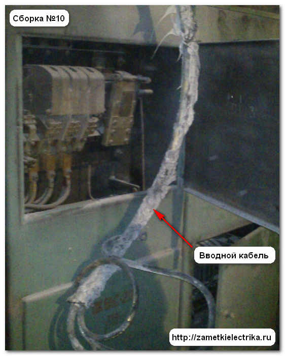
Naturally, no project documentation for shop electricians, according to the calculations of short-circuit currents. there was no one for this line, and I had to do the whole calculation myself, which I post in the public domain.
Data collection for calculation of short-circuit currents
Power assembly No. 10, near which the fire occurred, is powered through the circuit breaker A3144 600 (A) copper cable SBG (3x150) from step-down transformer No. 1 10 / 0.5 (kV) with a capacity of 1000 (kVA).
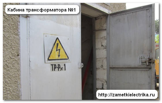
Do not be surprised, we still have many operating substations with isolated neutral at 500 (V) and even 220 (V) at our enterprise.
Soon I will write an article on how to network 220 (V) and 500 (V) with isolated neutral. Do not miss the release of a new article - subscribe to receive news.
Step-down transformer 10/0.5 (kV) is fed power cable AASHv (3x35) with high voltage distribution substation № 20.

Some clarifications for calculating the short circuit current
I would like to say a few words about the short circuit process itself. During a short circuit, transient processes occur in the circuit associated with the presence of inductances in it, which prevent a sharp change in current. In this regard, the short-circuit current during the transition process can be divided into 2 components:
- periodic (appears at the initial moment and does not decrease until the electrical installation is disconnected from protection)
- aperiodic (appears at the initial moment and quickly decreases to zero after the completion of the transient process)
Short circuit current I will calculate according to RD 153-34.0-20.527-98.
In that normative document it is said that the calculation of the short-circuit current is allowed to be carried out approximately, but on condition that the calculation error does not exceed 10%.
I will carry out the calculation of short-circuit currents in relative units. I will approximate the values of the circuit elements to the basic conditions, taking into account the transformation ratio of the power transformer.
The target is an A3144 with a current rating of 600 (A) per switching capacity. To do this, I need to determine the three-phase and two-phase short circuit current at the end of the power cable line.
Example of calculation of short-circuit currents
We take a voltage of 10.5 (kV) as the main stage and set the basic power of the power system:
basic power of the power system Sb = 100 (MVA)
base voltage Ub1 = 10.5 (kV)
short-circuit current on the busbars of substation No. 20 (according to the project) Ikz = 9.037 (kA)
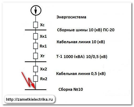
We draw up a calculation scheme for power supply.

In this diagram, we indicate all the elements of the electrical circuit and their. Also, do not forget to indicate the point at which we need to find the short circuit current. In the figure above, I forgot to indicate it, so I will explain in words. It is located immediately after the low-voltage cable SBG (3x150) before assembly No. 10.
Then we will draw up an equivalent circuit, replacing all the elements of the above circuit with active and reactive resistances.
When calculating the periodic component of the short circuit current, it is allowed to ignore the active resistance of cable and overhead lines. For a more accurate calculation, I will take into account the active resistance on cable lines.
Knowing the basic powers and voltages, we find the basic currents for each stage of transformation:

Now we need to find the reactive and active resistance of each circuit element in relative units and calculate the total equivalent resistance of the equivalent circuit from the power source (power system) to the short circuit point. (highlighted with a red arrow).
Let us determine the reactance of the equivalent source (system):
![]()
Let's determine the reactance of the cable line 10 (kV):

- Xo - specific inductive resistance for the AASHv cable (3x35) we take from the reference book on power supply and electrical equipment A.A. Fedorov, volume 2, tab. 61.11 (measured in Ohm/km)
Let's determine the active resistance of the cable line 10 (kV):
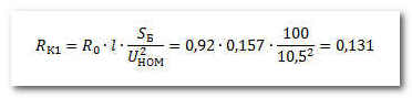
- Ro - specific active resistance for the AASHv cable (3x35) we take from the reference book on power supply and electrical equipment A.A. Fedorov, volume 2, tab. 61.11 (measured in Ohm/km)
- l is the length of the cable line (in kilometers)
Let's determine the reactance of a two-winding transformer 10 / 0.5 (kV):
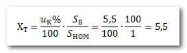
- uk% - short-circuit voltage of a transformer 10 / 0.5 (kV) with a power of 1000 (kVA), we take from the reference book on power supply and electrical equipment A.A. Fedorov, tab. 27.6
I neglect the active resistance of the transformer, because it is incommensurably small in relation to the reactive one.
Let's determine the reactance of the cable line 0.5 (kV):
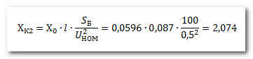
- Ho - resistivity for the SBG cable (3x150) we take from the reference book on power supply and electrical equipment A.A. Fedorov, tab. 61.11 (measured in Ohm/km)
- l is the length of the cable line (in kilometers)
Let's determine the active resistance of the cable line 0.5 (kV):
- Ro - resistivity for the SBG cable (3x150) we take from the reference book on power supply and electrical equipment A.A. Fedorov, tab. 61.11 (measured in Ohm/km)
- l is the length of the cable line (in kilometers)
Let's determine the total equivalent resistance from the power source (power system) to the short circuit point:
Find the periodic component of the three-phase short circuit current:
Find the periodic component of the two-phase short circuit current:

Short circuit current calculation results
So, we calculated the current of a two-phase short circuit at the end of a power cable line with a voltage of 500 (V). It is 10.766 (kA).
The introductory circuit breaker A3144 has a rated current of 600 (A). The setting of the electromagnetic release is set to 6000 (A) or 6 (kA). Therefore, we can conclude that in the event of a short circuit at the end of the input cable line (in my example, due to a fire), the damaged section of the circuit was disconnected.
The obtained values of three-phase and two-phase currents can also be used to select settings for relay protection and automation.
In this article, I did not perform the calculation for the shock current at short circuit.
P.S. The above calculation was sent to my management. For an approximate calculation, it will fit perfectly. Of course, the low side could be calculated in more detail, taking into account the resistance of the contacts of the circuit breaker, contact connections cable lugs to busbars, arc resistance at the point of short circuit, etc. I will write about this some other time.
If you need a more accurate calculation, you can use special programs on your PC. There are many of them on the Internet.
Required to complete calculation of three-phase short-circuit current (TKZ) on the buses of the designed ZRU-6 kV 110/6 kV substation "GPP-3". This substation is powered by two 110 kV overhead lines from the 110 kV GPP-2 substation. ZRU-6 kV "P4SR" receives power from two power transformers TDN-16000/110-U1, which work separately. When one of the inputs is disconnected, it is possible to supply power to the de-energized busbar section by means of a sectional switch in automatic mode (ATS).
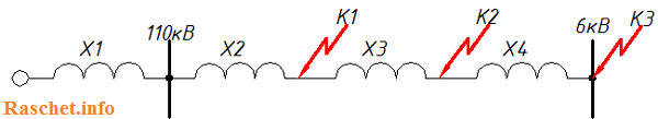
Figure 1 shows design scheme networks
Since the chain from I s.sh. "GPP-2" to I s.sh. "GPP-3" is identical to chain II s.sh. from "GPP-2" to II s.sh. "GPP-3" calculation is carried out only for the first chain.
The equivalent circuit for calculating short-circuit currents is shown in Figure 2.
The calculation will be made in named units.
2. Initial data for calculation
- 1. System data: Ikz=22 kA;
- 2. Data for overhead lines - 2xAS-240/32 (Data are given for one AC-240/32 circuit, RD 153-34.0-20.527-98, Appendix 9):
- 2.1 Direct sequence inductive reactance - Х1ud=0.405 (Ohm/km);
- 2.2 Capacitive conductivity - wsp=2.81x10⁻⁶ (S/km);
- 2.3 Active resistance at +20 C per 100 km of the line - R=R20C=0.12 (Ohm/km).
- 3. Transformer data (taken from GOST 12965-85):
- 3.1 TDN-16000/110-U1, Uin=115 kV, Un=6.3 kV, on-load tap-changer ±9*1.78, Uk.in-nn=10.5%;
- 4. Data of the flexible conductor: 3хАС-240/32, l=20 m. (To simplify the calculation, the resistance of the flexible conductor is not taken into account.)
- 5. Data of the current limiting reactor - RBSDG-10-2x2500-0.2 (taken from GOST 14794-79):
- 5.1 Rated current reactor - Inom. = 2500 A;
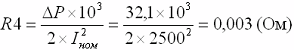
- 5.2 Nominal power losses per reactor phase - ∆P= 32.1 kW;
- 5.3 Inductive resistance - Х4=0.2 Ohm.
3. Calculation of element resistances
3.1 System resistance (for voltage 115 kV):
![]()
3.2 Resistance overhead line(for voltage 115 kV):
Where:
n - Number of wires in one overhead line VL-110 kV;
3.3 Total resistance to the transformer (for voltage 115 kV):
X1.2 \u003d X1 + X2 \u003d 3.018 + 0.02025 \u003d 3.038 (Ohm)
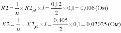
R1.2=R2=0.006 (Ohm)
3.4 Transformer resistance:
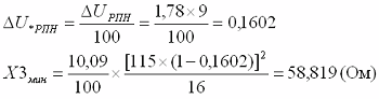
3.4.1 Active resistance of the transformer (OLTC is in the middle position):
3.4.2 Active resistance of the transformer (OLTC is in the extreme "minus" position):
3.4.3 Active resistance of the transformer (OLTC is in the extreme "positive" position):
Minimum inductive resistance of the transformer (OLTC is in the extreme "minus" position)

The maximum inductive resistance of the transformer (OLTC is in the extreme "positive" position)

The value included in the formula above is the voltage corresponding to the extreme positive position of the on-load tap-changer, and it is equal to Umax.VN = 115 * (1 + 0.1602) = 133.423 kV, which exceeds the highest operating voltage of electrical equipment equal to 126 kV (GOST 721-77 " Power supply systems, networks, sources, converters and receivers electrical energy. Rated voltages over 1000 V"). The voltage UmaxVN corresponds to Uk%max=10.81 (GOST 12965-85).
If Umax.VN, it turns out more than the maximum allowable for this network (Table 5.1), then Umax.VN should be taken according to this table. The value Uk% corresponding to this new maximum value Umax.VN is determined either empirically or found from the applications of GOST 12965-85.

3.4.5 Resistance of the current-limiting reactor (at a voltage of 6.3 kV):
4. Calculation of three-phase short-circuit currents at point K1
4.1 Total inductive reactance:
X∑=X1.2=X1+X2=3.018+0.02025=3.038 (Ohm)
4.2 Total active resistance:
R∑=R1.2=0.006 (Ohm)
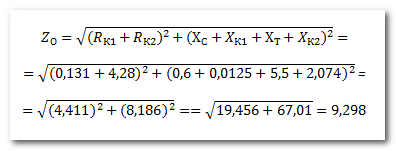
4.3 Total impedance:
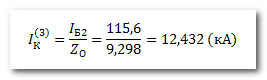
4.4 Three-phase short circuit current:

4.5 Surge short-circuit current:

5. Calculation of three-phase short-circuit currents at point K2
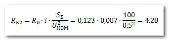
6.1.1 The value of the total resistance at point K2, we lead to a network voltage of 6.3 kV:
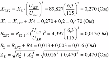
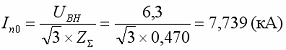
6.1.2 The current at the place of a short circuit, reduced to an effective voltage of 6.3 kV, is equal to:
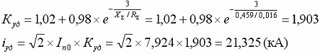
6.1.3 Surge short-circuit current:

6.2 Resistance on the busbars of the ZRU 6 kV with the on-load tap-changer of the T3 transformer set to the minus position
6.2.1 The value of the total resistance at point K2 is reduced to a network voltage of 6.3 kV:
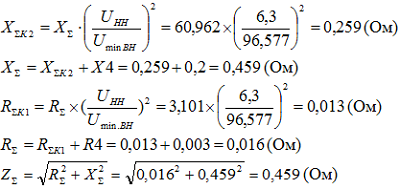
6.2.2 The current at the place of the short circuit, reduced to an effective voltage of 6.3 kV, is equal to:

6.2.3 Surge short-circuit current:
6.3 Resistance on the busbars of the ZRU 6 kV with the on-load tap-changer of the T3 transformer installed in the positive position
6.3.1 The value of the total resistance at point K2, we lead to a network voltage of 6.3 kV:

6.3.2 The current at the place of the short circuit, reduced to an effective voltage of 6.3 kV, is equal to:

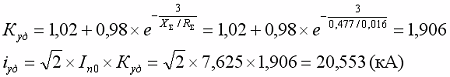
6.3.3 Surge short-circuit current:
The results of the calculations are entered in table РР1.3
Table РР1.3 - Calculation data for three-phase short-circuit currents
| Transformer tap position | Short circuit currents | Short circuit point | ||
|---|---|---|---|---|
| K1 | K2 | K3 | ||
| Tap changer in middle position | Short circuit current, kA | 21,855 | 13,471 | 7,739 |
| Surge current short circuit, kA | 35,549 | 35,549 | 20,849 | |
| Short circuit current, kA | - | 13,95 | 7,924 | |
| Surge current short circuit, kA | - | 36,6 | 21,325 | |
| Tap changer in positive position | Short circuit current, kA | - | 13,12 | 7,625 |
| Surge current short circuit, kA | - | 34,59 | 20,553 | |
7. Calculation of short circuit current made in Excel
If you perform this calculation using a piece of paper and a calculator, it takes a lot of time, besides, you can make a mistake and the whole calculation will go down the drain, and if the initial data is constantly changing, this all leads to an increase in design time and unnecessary waste of nerves.
Therefore, I decided to perform this calculation using an Excel spreadsheet, so as not to waste my time on recalculating the TKZ and protect myself from unnecessary errors, with its help you can quickly recalculate the short circuit currents, changing only the initial data.
I hope that this program will help you and you will spend less time designing your facility.
8. References
- 1. Guidelines for the calculation of short-circuit currents and the choice of electrical equipment.
RD 153-34.0-20.527-98. 1998 - 2. How to calculate the short circuit current. E. N. Belyaev. 1983
- 3. Calculation of short circuit currents in power networks 0.4-35 kV, Golubev M.L. 1980
- 4. Calculation of short circuit currents for relay protection. I.L. Nebrat. 1998
- 5. Rules for the installation of electrical installations (PUE). Seventh edition. 2008