Artificial lighting sources that use an electrical discharge of a gaseous medium in mercury vapor to produce light waves are called gas-discharge mercury lamps.
The gas pumped into the cylinder can be at low, medium or high pressure. Low pressure is used in lamp designs:
linear luminescent;
compact energy-saving:
bactericidal;
quartz.
High pressure is used in lamps:
arc mercury phosphor (MAF);
metallogenic mercury with radiating additives (RAI) of metal halides;
arc sodium tubular (NAT);
arc sodium mirror (DNaZ).
They are installed in places where it is necessary to illuminate large areas with low energy consumption.
DRL lamp
Design Features
The design of a lamp using four electrodes is shown schematically in the picture.
Its base, like that of regular models, serves to connect to contacts when screwed into the cartridge. The glass flask hermetically protects all internal elements from external influences. It contains nitrogen and contains:
quartz burner;
electrical conductors from the base contacts;
two current-limiting resistors built into the circuit of additional electrodes
phosphor layer.
The burner is made in the form of a sealed tube made of quartz glass filled with argon, in which are placed:
two pairs of electrodes - main and additional, located at opposite ends of the flask;
a small drop of mercury.
Argon - chemical element, which refers to inert gases. It is obtained through the process of air separation during deep cooling followed by rectification. Argon is a colorless and odorless monatomic gas, density 1.78 kg/m3, boiling point = –186 °C. Argon is used as an inert medium in metallurgical and chemical processes, in welding equipment (see), as well as in signal, advertising and other lamps that give a bluish light.
Operating principle of DRL lamps
The DRL light source is a discharge electric arc in an argon environment flowing between the electrodes in a quartz tube. It occurs under the influence of voltage applied to the lamp in two stages:
1. Initially, a glow discharge begins between the closely located main and ignition electrodes due to the movement of free electrons and positively charged ions;
2. formation inside the burner cavity large quantity charge carriers leads to rapid breakdown of the nitrogen medium and the formation of an arc through the main electrodes.
Stabilization of the starting mode ( electric current arc and light) requires about 10÷15 minutes. During this period, the DRL creates loads that significantly exceed the rated mode currents. To limit them, .
Arc radiation in mercury vapor is blue and purple shade and is accompanied by powerful ultraviolet radiation. It passes through the phosphor, mixes with the spectrum it creates and creates a bright light that is close to white.
The DRL is sensitive to the quality of the supply voltage, and when it drops to 180 volts, it goes out and does not light up.
During the creation high temperature, transmitted to the entire structure. It affects the quality of the contacts in the socket and causes heating of the connected wires, which because of this are used only with heat-resistant insulation.
When the lamp is operating, the gas pressure in the burner increases greatly and complicates the conditions for breakdown of the medium, which requires an increase in the applied voltage. If the power is turned off and applied, the lamp will not start immediately: it needs to cool down.
DRL lamp connection diagram
A four-electrode mercury lamp is switched on through a choke and.

The fuse link protects the circuit from possible short circuits, and the inductor limits the current passing through the medium of the quartz tube. The inductive reactance of the choke is selected according to the power of the lamp. Turning on the lamp under voltage without a choke leads to its rapid burnout.
A capacitor included in the circuit compensates for the reactive component introduced by the inductance.
DRI lamp
Design Features
The internal structure of the DRI lamp is very similar to that used by the DRL.

But its burner contains a certain dose of additives from hapogenides of the metals indium, sodium, thallium or some others. They allow you to increase the light output to 70÷95 lm/W or more with good color.
The flask is made in the shape of a cylinder or ellipse, shown in the figure below.

The burner material can be quartz glass or ceramics, which has better performance properties: less dimming and longer service life.
Ball burner shape used in modern designs, increases the light output and brightness of the source.
Operating principle
The main processes occurring during the production of light from DRI and DRL lamps are the same. The difference is in the ignition circuit. The DRI cannot be put into operation by the applied mains voltage. This size is not enough for her.
To create an arc discharge inside the torch, it is necessary to apply a high-voltage pulse to the interelectrode space. Its formation is entrusted to the IZU - a pulsed ignition device.
How does IZU work?
The operating principle of the device for creating a high-voltage pulse can be conventionally represented by a simplified circuit diagram.

The operating supply voltage is supplied to the input of the circuit. In a chain of diode D, resistor R and capacitor C, a charging current containers. At the end of the charge, a current pulse is issued through the capacitor through the opened thyristor switch into the winding of the connected transformer T.
A high-voltage pulse of up to 2÷5 kV is created in the voltage-increasing output winding of the transformer. It enters the lamp contacts and creates an arc discharge of the gaseous medium, which provides the glow.
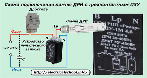
Connection diagrams for a DRI type lamp
IZU devices are produced for gas discharge lamps two modifications: with two or three terminals. For each of them, its own connection diagram is created. It is located directly on the block body.
When using a two-contact device, the network phase is connected through a choke to the central contact of the lamp base and at the same time to the corresponding output of the IZU.

The neutral wire is connected to the side contact of the base and its output of the IZU.
For a three-pin device, the zero connection diagram remains the same, but the phase supply after the inductor changes. It is connected through the two remaining pins on the IZU, as shown in the picture below: the input to the device is through the “B” terminal, and the output to the central contact of the base is through “Lp”.
Thus, the ballasts for mercury lamps with emitting additives must include:
throttle;
pulse charger.
Compensating value reactive power The capacitor may be part of the ballast. Its inclusion determines the overall reduction in energy consumption of the lighting device and the extension of the life of the lamp with the correctly selected capacity.
Approximately its value of 35 μF corresponds to lamps with a power of 250 W, and 45 - 400 W. When the capacitance is too high, a resonance occurs in the circuit, which is manifested by the “blinking” of the lamp light.
The presence of high voltage pulses in a working lamp determines the use in the connection circuit of exclusively high-voltage wires of a minimum length between the ballast and the lamp, no more than 1÷1.5 m.
DRIZ lamp
This is a variation of the DRI lamp described above, inside the bulb of which a mirror coating is partially applied to reflect light, which forms a directed stream of rays. It allows you to focus radiation on the illuminated object and reduce light losses arising from reflections.
HPS lamp
Design Features
Inside the bulb of this gas-discharge lamp, instead of mercury, sodium vapor is used, located in an environment of inert gases: neon, xenon or others, or mixtures thereof. For this reason they are called "sodium".
Due to this modification of the device, the designers managed to give them the highest operating efficiency, which reaches 150 lm/W.
The principle of operation of DNAT and DRI is the same. Therefore, their connection diagrams are the same and, if the characteristics of the ballasts correspond to the parameters of the lamps, they can be used to ignite the arc in both designs.
However, manufacturers of metal halogen and sodium lamps They produce ballasts for specific types of their products and supply them in a single housing. These ballasts are fully adjusted and ready to work.
Connection diagrams for HPS lamps
In some cases, the designs of ballasts for HPS may differ from the DRI launch schemes presented above and be carried out according to one of the three schemes below.
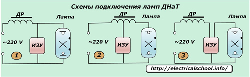
In the first case, the IZU is connected in parallel to the lamp contacts. After the arc is ignited inside the torch, the operating current does not flow through the lamp (see schematic diagram IZU), which saves electricity consumption. In this case, the inductor is exposed to high-voltage pulses. Therefore, it is created with reinforced insulation to protect against ignition impulses.
Because of this, the scheme parallel connection used with low power lamps and ignition pulses up to two kilovolts.
The second scheme uses an IZU that operates without pulse transformer, and high-voltage pulses are generated by a specially designed inductor, which has a tap for connection to the lamp contact. The insulation of the windings of this inductor is also enhanced: it is exposed to high voltage voltage.
In the third case, the method is used serial connection choke, IZU and lamp contact. Here, the high-voltage pulse from the IZU does not enter the inductor, and the insulation of its windings does not require amplification.
The disadvantage of this circuit is that the IZU consumes increased current, which causes additional heating. This necessitates an increase in the dimensions of the structure, which exceed the dimensions of the previous schemes.
This third design option is most often used to operate HPS lamps.
In all schemes it can be used by connecting a capacitor as shown in the diagrams for connecting DRI lamps.
The listed lamp switching circuits high pressure, using a gas discharge for glow, have a number of disadvantages:
reduced glow resource;
dependence on the quality of the supply voltage;
stroboscopic effect;
noise of operating throttle and ballasts;
increased electricity consumption.
Most of these shortcomings are eliminated by the use of electronic launchers (EPG).

They not only allow you to save up to 30% of electricity, but also have the ability to smoothly control the lighting. However, the cost of such devices is still quite high.
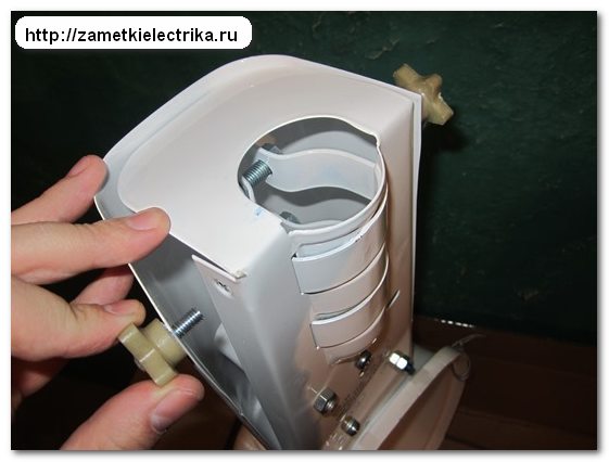
Hello, dear readers of the Electrician's Notes website.
To get to the terminal block, you need to unscrew 2 bolts with plastic heads (wings) and tilt the lamp.

The cores of the power cable are connected to the terminal block of the lamp as follows:

As you can see, . Phase (L) must be connected to a terminal with two outgoing white wires, zero (N) - with a blue outgoing wire, and protective conductor(RE) - in the center.
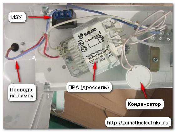
Now let’s look at the internal diagram of the housing and communal services lamp.
Connection diagram for a lamp for sodium lamps
Due to the design features and operating principle of sodium lamps, when connecting them you need:
- pulse ignition device (IZU)
- compensation capacitor
control gear (ballast), also called a throttle or ballast
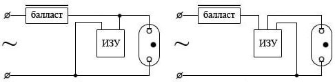
There are two schemes for connecting HPS lamps:

In my case, the second scheme is used:
![]()
I specifically highlighted the wires in the diagram with the appropriate color, which you will see in the photographs below.


Schematic elements
Let's consider all the elements that are included in this diagram:
1. Ballast (choke)
In general, there are two types of ballasts (chokes):
- electromagnetic or inductive (EMPRA)
- electronic (electronic ballasts)
Each ballast has its own advantages and disadvantages. I will tell you about this in my next articles (in order not to miss new articles, subscribe to the newsletter).
The luminaire in question uses a domestic built-in electromagnetic single-winding ballast (choke) “Galad” 1I70DNaT46N-666 UHL2. It is connected in series with the lamp, thereby limiting and stabilizing its current consumption. By the way, it weighs 1.3 (kg) and its retail price is about 350-390 rubles.
My point is that you should be guided by prices, in case you have to change it, because they often fail. There may be several reasons: an interturn short circuit in the winding, or a break in it.
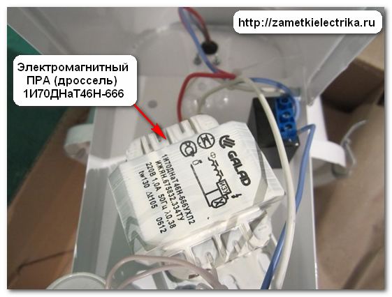
The throttle body shows its connection diagram and some characteristics.
- power 70 (W)
- voltage 220 (V)
- operating current of lamp 1 (A)
- starting current lamps no more than 1.6 (A)
- power factor 0.38
- current consumed from the network 0.54 (A)
- maximum permissible temperature windings in operating mode 130°С
2. Pulse ignition device (IZU)
There are two types of IZU:
- with three terminals
- with two terminals
In our example, we use the domestic compact IZU-1M 35/70-3 from Remar LLC with three terminals. The retail price is about 120-150 rubles.

The IZU is necessary to “start” the HPS lamp. When the lamp is turned on, it delivers a short-term high-voltage pulse of 1.8-2.5 (kV), which ensures breakdown of the gas gap in the lamp bulb.
IZU is not required for DRL lamps.

The connection diagram and some characteristics can be seen on its body.
- voltage 220 (V)
- response voltage 170-195 (V)
- HPS lamp power 35-70 (W)
- parallel connection type
- pulse amplitude 1.8-2.5 (kV)
- pulse duration not less than 1.62 (μs)
3. Capacitor
To increase the power factor (cosine “phi”) of the lamp, a capacitor is used. In my case, this is a polypropylene film capacitor K78-99 with a capacity of 10±10% (uF) with a voltage of 250 (V), which is connected in parallel to the supply network (directly to the terminal block).
Before compensation, the cosine of the lamp was 0.38, after compensation it was 0.85.
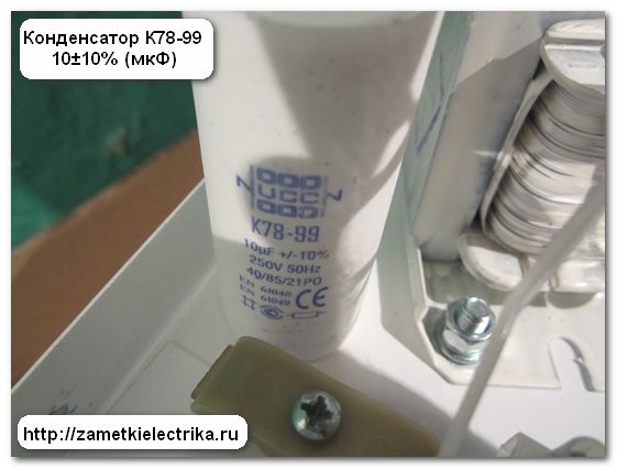
Each type of inductor requires a certain capacitor capacity. You can calculate it using formulas yourself, or you can use special tables from manufacturers.
Maintenance of luminaires with HPS lamps
If carried out in a timely manner maintenance lamps, their service life will correspond to that stated in the passport. You just need to periodically perform the following steps:
check reliability contact connections in the terminal block, choke and IZU
clean the lamp from dust and dirt
if the HPS lamp burns out, then install a lamp of the same power in its place, and not more or less
P.S. That's probably all. If you have questions about the topic of the article, I am ready to answer them. Thank you for your attention.
To ignite gas-discharge lamps, including sodium lamps, you will need specialized ballast equipment (ballast control equipment), because direct connection of HPS lamps to the network is excluded.
Ballasts for sodium lamps (HPS) include:
- IZU (pulse ignition device), which ensures the start of a gas-discharge lamp. At the moment it is turned on, the IZU passes powerful high-voltage pulses to the electrodes, due to which a breakdown occurs in gas mixture bulbs and arc ignition. After this, the issuance of explosive pulses stops, however, as does the influence of the pulse ignition device on the operation of the lamp;
- Throttle. Although electronic ballasts are considered more productive, their cost is much more expensive than pulsed ones. Therefore, the most common and in demand for connecting a HPS lamp is an inductive choke. The electric choke is presented in the form of a small block, which must correspond to the power consumption of the lamp. It limits and stabilizes the current supply, strongly resists any changes in it, maintains a decreasing current and prevents its increase, thereby ensuring long-term performance properties of the lamp and high luminous efficiency.
Thus, the ballast provides standard heating and efficient operation of sodium lamps for the entire period stated by the manufacturers.
HPS connection. Scheme
Possible different methods connections of gas-discharge lamps, in this case HPS: IZU manufacturers can offer a design with two or even three contacts, with parallel, serial and even semi-parallel types, which significantly changes the HPS connection scheme. It is displayed on almost all devices of this type, which eliminates installation errors.

The connection diagram for the HPS lamp, which is shown in the first figure, is designed to contain a compensating capacitor connected in parallel to the power source. This is a dry type C capacitor, which is designed to compensate for the inductive component of the system - reducing reactive power consumption, reducing overall electricity consumption, as well as extending the service life of the finished product.
For example, to connect a HPS lamp with a power of 250 W (3A), a compensating capacitor capacity (operating voltage indicators - 250V) of only 35 μF is provided. This capacitance can be formed using several capacitors connected in parallel.
Sometimes capacitance indicators may be provided by the manufacturer, but an extremely large increase can lead to resonance in the circuit, and, consequently, to ineffective operation of the finished product.
If the HPS connection occurs independently, you should take into account valid value location of the IZU. It should be located as close as possible to the base of the product, while the length of the connecting wires in this area should be minimal (the maximum permissible value is 1.5 m).
To ensure high-quality and safe connection, high-voltage ignition wires for special purposes are used.
Reviews
Guest- 07 Feb 2014 23:58:53
In my opinion, the phase in the lamp is where you have zero.
Igor- 08 Feb 2014 14:56:03
In fact, the lamp will work well with any connection of phase and zero to its base.
But there is a safety issue.
And here you are right.
The pictures do not show the socket into which the lamp is screwed.
For clarity, I omitted it from the diagram.
Assuming that you are unscrewing a burnt-out lamp and at the same time:
1.phase is connected to the threaded part of the cartridge (as in the pictures)
2.You forgot to turn off the switch, or it opens zero, not phase
Then when you touch the base you will get a good knock.
And if the phase is connected to the central contact of the base, then the chance of electric shock is minimal.
But personally, I would unscrew the lamp while holding onto its glass bulb. When the power is off. And I wouldn’t think about the connected phase.
But anyway, thanks for the clarification.
Vitaly- 18 Feb 2014 8:57:24
And what should the phrase “...IZU manufacturers can offer a design with two or even three contacts...” mean? All normal manufacturers of sodium lamps, Philips, OSRAM, General Electric, launch their sodium lamps exclusively in series or semi-parallel circuits, with the exception of lamps with a built-in ignitor. And this means the presence of exactly three contacts. A parallel ignitor (which has two contacts) cannot be used to start such lamps, since the vast majority of ballasts do not have protection against high-voltage pulses and will fail very quickly. Therefore, parallel connection used to start sodium lamps low pressure or metal halide lamps designed to operate with mercury ballast and do not require high-voltage starting pulses. Based on this, I undertake to assert that scheme No. 2, made up of precisely these components, is not correct. The VS catalog, whose ballast is used for the example, can confirm this. The DeLux ignitor was used to start sodium lamps only in combination with a ballast specially produced for this circuit.
What am I doing wrong?
Alexey- 02 Oct 2014 23:16:14
Hello, could you please tell me the connection diagram for the Philips sox-e 131w low pressure lamp?
When using conventional scheme with a two-pin izu it starts to twitch, but does not light up
Guest- 04 Nov 2014 11:48:27
everything lights up perfectly with any ignitor connection diagram, both parallel and serial 3-pin!!!
Sergey- 29 Nov 2014 10:08:52
Good afternoon, could you please tell me the connection diagram:
1 gas-discharge sodium lamp lhp-t 100 W
2 isut 70-700DNaT/220v-02.ukhl2 (2 contacts)
3 ballast galad 1i250drl44-033uhl1 (three contacts, and they are marked 1 2 3)
thanks in advance
Among all the lamps for artificial lighting For plants, a sodium lamp is most suitable, which is very popular.
This light source is highly efficient, and is the most economical and durable. The lamp power can range from 30 to 1000 W, depending on the area of use. As for the service life, the lamp life is designed for 25,000 hours of operation. For most greenhouses, this is a profitable option in terms of savings, since the plants need to be illuminated quite long time, especially in winter.
Russian Reflex lamps, which are equipped with a built-in reflector, are in great demand on the market. Due to this, the light is directed directly at the plants. The Reflex lamp reflector has high efficiency equal to 95%, which remains throughout the entire period of operation. Typically, one Reflax lamp with a power of 70 Watt, suspended at a height of half a meter, is capable of illuminating an area of about 1.6 m2. And since the use of other light sources implies high energy costs, the use of Reflux lamps is more rational. As for the dimensions, Reflax has dimensions of 76x200 mm. Thanks to this, Reflex lamps are best suited for greenhouse owners.
Advantages and disadvantages of sodium lamps
The sodium lamp has significant benefits:
• High efficiency.
• Stable light flow.
• High luminous efficiency of approximately 160 lm/W.
• Long service life, which is 1.5 times longer than the service life of other similar lamps.
• The lamps have a pleasant golden-white emission.
• Efficient work in foggy conditions.
Due to the fact that arc lamp reflex 250 emits a red spectrum - this ideal source light for flowering plants, including fruit-bearing ones. And the presence of a blue light spectrum contributes to their active growth and development. In addition, the lamps can operate in a wide temperature range - from -60 to +40 degrees.
Along with the advantages, there are also some disadvantages. The main one is the complexity of the connection. Normal way does not fit here, and there are some peculiarities here. Other disadvantages include the following:
• Explosion hazard.
• Presence of mercury in the lamp structure.
• For a long time switching on, which can last up to 10 minutes.
• Not suitable for growing non-flowering or green vegetable crops(radish, onion, lettuce).
In addition, if it is necessary to use high-pressure sodium lamps of 250 watts or more, care must be taken to ensure cooling as the lamps become very hot. Although for greenhouses large size this disadvantage can turn into an advantage by providing the plants with additional heat.
Operating principle
By appearance Sodium light sources are a bit like DRL lamps. There is also a glass flask of elliptical or cylindrical, inside it there is a discharge tube (“burner”), on each side of which there are electrodes. These leads are connected to a threaded base. Due to the fact that sodium vapor has a strong effect on glass, this material is not suitable for making a “burner”. It is made from polycor (polycrystalline aluminum oxide), which increases resistance to sodium vapor and transmits up to 90% of visible light. The DNAT 400 lamp has a discharge tube with a diameter of 7.5 mm and a length of 80 mm. The tube electrodes are made of molybdenum.
In addition to sodium vapor, the discharge tube composition contains argon to facilitate starting the lamps, and also contains mercury or xenon, which allows for increased luminous efficiency. During operation, the “burner” heats up to 1300 °C and in order to keep it intact, air is pumped out of the flask. However, it is difficult to maintain a vacuum while the lamp is running because air can leak through the holes. Therefore, special gaskets are used to prevent this. It is worth noting that when the lamp is operating, its bulb heats up to 100 °C. When a pulse ignition device (IZD) is turned on, a pulse voltage is created, resulting in the formation of an arc. But at first, the sodium lamps DNAT reflex 250 still shine weakly, since all the energy is spent on heating the tube. After 5 or 10 minutes, the brightness of the light returns to normal.

How to connect a sodium lamp
Due to the special structure of gas-discharge lamps, it is not possible to simply connect them to a household electrical network, since the available voltage is not enough to start. In addition, the arc current must be limited. And sodium lamps are no exception. In this regard, it is necessary to use a ballast or ballast in the circuit. They can be electromagnetic (EMP) or electronic (EPG). In practice in Western countries, such devices are called Magnetic Ballast (for electronic ballasts) and Digital Ballast (for electronic ballasts). In some cases, it is impossible to do without the use of a pulse ignition device or IZU.
The use of electronic ballasts for sodium lamps 250 is necessary for their heating and further uninterrupted operation. In this case, the launch itself takes 3-5 minutes, and full power sodium lights are dialed in for another 10 minutes. It is noteworthy that at the moment the lamp is started, its rated voltage increases almost 2 times.

Ballast device
The ballast consists of three main components:
• Inductive choke.
• IZU.
• Phase compensating capacitor.
The choke serves to limit the arc current and its power must be the same as that of the lamp used. For example, if a HPS 250 lamp is used, then, accordingly, the power of the inductor should also be no less and no more than 250 Watts. IN lately The lamp connection diagram often includes a single-winding choke, while double-winding ones are already obsolete.
IZU is necessary to increase the voltage to several kilovolts in order to form an arc. The power of the IZU can range from 35 to 400 Watts. In addition, the device can be of a two-pin or three-pin design. Moreover, the use of three-pin IZU is preferable.
As for the capacitor, this is an optional component. But its presence provides certain advantages, as it allows you to reduce the load on the household electrical network. In turn, this reduces the risk of a wiring fire to a minimum. More details will be discussed below.
Connection diagrams for HPS lamps
Depending on which IZU is used (with two terminals or three), 250 Watt high pressure sodium lamps can be connected in different ways. This is reflected in more detail in the diagram below.
 Sodium lamp connection diagram
 As you can see from the figures, the inductor (ballast) is connected in series, but the IZU is connected to the circuit in parallel.
To operate, sodium lamps use reactive power. In this regard, it is desirable that the connection diagram include a special capacitor, which will suppress interference and reduce the inrush current. Which ultimately extends the life of the lamps. Also, this element is simply irreplaceable in the absence of a phase compensator.
As can be seen in the first figure, the presence of a phase-compensating capacitor is shown by a dotted line. Its connection is carried out in parallel with the power source.
The main thing is to choose a capacitor with optimal electrical capacity. For example, when using the same DNAT-250 lamp, its capacity should be 35 microfarads. If the circuit contains a DNaT 400 lamp, then you can choose a capacitor with a slightly larger capacity - 45 μF. Only dry elements and those designed for a voltage of at least 250 V are allowed to be used in the circuit.
At self-connection lamps is worth taking note of. The length of the wire connecting the light source itself and the inductor should not exceed one meter.
Precautions
In force design features 250 sodium discharge lamp, extreme caution must be used when operating these light sources. It is unacceptable to turn off the lamp immediately after turning it on. It should remain on for at least 1 or 2 minutes. Otherwise, the lamp will stop turning on altogether and then it must be de-energized and wait a while.
In the room where lamps operate, it is necessary to have high-quality ventilation. Its temperature during operation can rise to 100 degrees or more. And according to some sources, all 1000. Therefore, good ventilation is the key to long and safe work lighting sources. Do not touch high-pressure lamps with your hands during operation to avoid burns. The same goes for its reflector.
When installing lighting sources, you do not need to handle the bulb with bare hands; it is best to use cloth gloves. Or you can wrap it in some paper or cardboard to avoid leaving greasy fingerprints on the glass. Since the heating temperature is very high, any grease deposits or even drops of water can cause the lamp to explode. You can find a lot of information about this on the Internet.
But not only high-pressure lamps can get very hot, this also applies to the ballast used. Its temperature can rise to 80-150 degrees. Therefore, as a precaution, this element of the circuit should be insulated, hidden under a fireproof and durable casing. This will prevent dry leaves, pieces of fabric or paper, and other objects from getting inside.
Don’t forget about basic safety precautions when working with electricity. That is, eliminate any possibility of water getting into the ballast, and monitor the integrity of the electrical wiring. It is always worth remembering that at the moment when the HPS lamp starts, the IZU generates high voltage pulses. Therefore, it is best to use special wires that are designed to work in extreme conditions. They are just designed for high heat.
Disposal
Sodium, by its nature, is a volatile substance and, in contact with air, can ignite rapidly. For this reason, sodium light sources should not be disposed of as regular waste. Like any energy saving lamp, which contains mercury, they also need to be disposed of in special containers. If you cannot dispose of HPS sodium lamps yourself while observing safety precautions, you should call a special service.
To connect any gas-discharge lamps, a ballast is required. Sodium lamps are no exception in this sense; To “warm up” the lamps when turned on and for their normal operation, a ballast will be required. Ballast for sodium lamps is a ballast (ballast) or electronic ballast (electronic ballast) and IZU (pulse ignition device).
The most common ballasts for sodium lamps are ballast inductive chokes, which are necessary to stabilize and limit the current. The IZU is necessary, as described above, for “warming up” - lighting the lamp. When a sodium lamp is turned on, this device, which is a small block, delivers a powerful high-voltage pulse to its electrodes, causing a breakdown in the gas mixture of the flask.
Connection diagrams. Although, sodium lamps today have received quite wide application in a variety of industries, due to insufficient transmission of the color spectrum, they are most often used as street lighting.
 These are “street” lamps that replace DRL
, for which console lamps of the brand are produced Housing and communal services. They already have the necessary ballast, properly connected to the lamp, therefore, when using such lamps, the connection is reduced to only supplying the supply voltage to the terminals of the lamp.
These are “street” lamps that replace DRL
, for which console lamps of the brand are produced Housing and communal services. They already have the necessary ballast, properly connected to the lamp, therefore, when using such lamps, the connection is reduced to only supplying the supply voltage to the terminals of the lamp.
To independently assemble a connection diagram for sodium lamps, you will need, as described above, a ballast - a choke and an IZU. Double-winding chokes are considered obsolete today, therefore, when choosing, preference should be given to single-winding ones.
IZU manufacturers produce devices with two and three terminals, therefore, the connection diagram may differ slightly - it, in fact, is depicted on almost every IZU case.
Sodium lamps are consumers of reactive power, therefore, in some cases, it makes sense, in the absence of phase compensation, to include an interference suppression capacitor C in the circuit, which significantly reduces the inrush current (see photo above).
For throttle DNAT-250 (3A) optimal capacity capacitor – 35 µF, for DNAT-400 (4.4A) – 45 µF. Dry type capacitors should be used, with rated voltage from 250 V. In this case, the connection diagram will look like this:

When connecting lamps yourself, it is worth considering the recommendation not to allow the length of the wires connecting the ballast to the lamp to exceed more than one meter.
Finally, about ballast. Undoubtedly, electronic ballasts are rightfully considered the best, having a number of advantages over inductive ballasts, but losing, however, to the latter in price; Their cost is currently quite high.