Hello, dear readers and guests of the Electrician's Notes website.
In today's article I want to tell you about how insulation control is carried out DC voltage 220 (V) at the substations of our enterprise. Insulation control is what we call KIZ in short.
So, all our operational circuits are made on direct current.
Operating circuits include control circuits high voltage circuit breakers, relay protection and automation circuits (SHU buses), switching circuits or, in other words, circuits of solenoids (electromagnets) of switch drives (SHV buses), emergency and warning alarm circuits (ShS buses).
Also, emergency lighting of substations is powered from the DC switchboard (DCB), although in the event that there are no .

The source of direct current is rechargeable batteries (AB). Batteries are the most reliable power source, because... provide the necessary voltage to power operational circuits at any time of the day. True, for this you need to have a separate room, additional equipment in the form of charging and recharging units of the VAZP type and specially trained personnel to service them.
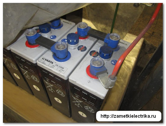
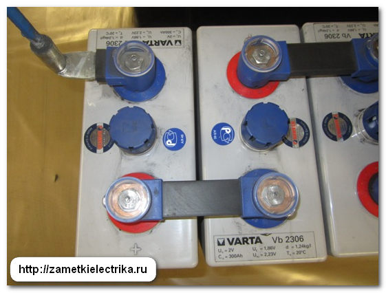
We still have SK-5 type lead-acid batteries installed at our substations. True, not so long ago we began to switch to new maintenance-free Varta batteries. I'll write about this some other time.
At remote substations, where it is not possible to power the operating circuits from a battery, BPN and BPT power supplies are used as a DC source.
The voltage level of operational circuits is generally 220 (V), less commonly 48 (V) is used, but this is quite the case in old substations.
Naturally, during operation it is necessary to control the insulation resistance of the “+” and “-” poles relative to the ground, otherwise in the event of a leak (short circuit) to the ground, depending on the nature of the short circuit, the control of the substation equipment may either fail (disappear), or vice versa, false shutdown or activation via bypass circuits.
To prevent such cases, it is necessary to control the appearance of “ground” in DC circuits. By the way, this is also stated in the PUE, paragraph 3.4.18:

Our direct operating current networks are very branched, so we definitely cannot do without monitoring the insulation of their poles relative to the ground.
Damage to operational circuits must be identified and repaired as quickly as possible.
We use two insulation monitoring schemes:
- with two additional resistances and a milliammeter
- with two additional resistances, milliammeter and current relay
Now let's look at each scheme in more detail.
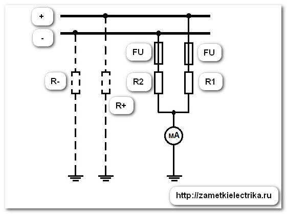
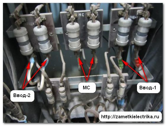
A simple circuit in which the “+” from the direct current switchboard (DCB) is connected to the output of one additional resistance (AR), and the “-” minus is connected to the output of another additional resistance (AR). On the other hand, their conclusions are connected to each other at a common (middle) point. The common (middle) point is connected to the substation through a milliammeter (mA).

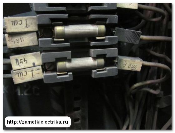
As a protection device in this circuit, PPT-10 fuses with a VTF insert with rated current 10 (A).
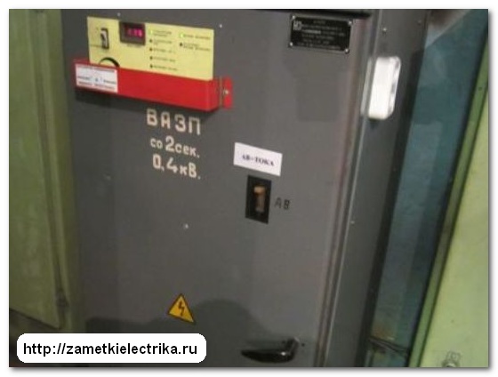
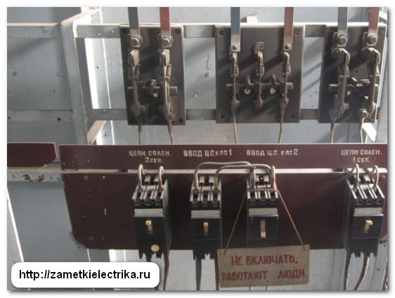
Instead of fuses PPT-10 can be installed two-pole circuit breaker AP-50 with a rating of 4 (A), 6.3 (A) or 10 (A). Here's an example:

Sometimes, a toggle switch or switch is installed in the gap between the milliammeter and ground so that the insulation monitoring circuit is not constantly in operation.


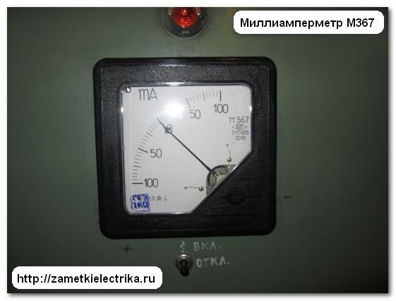
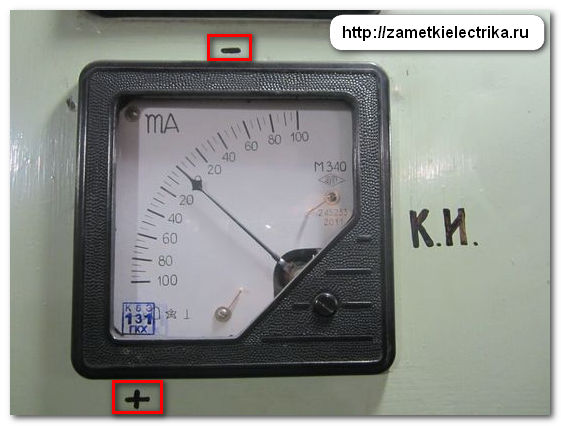
In my example, a panel milliammeter of type M367 is installed. Its scale is made with zero in the middle, i.e. It can measure DC current in both directions from 0 to 100 (mA).
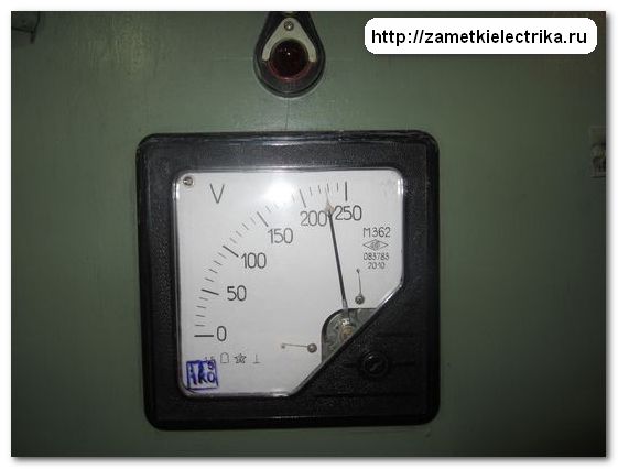
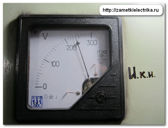
To control the voltage level, a voltmeter type M362 with a limit of 250 (V) is installed on this direct current switchboard (DCB).
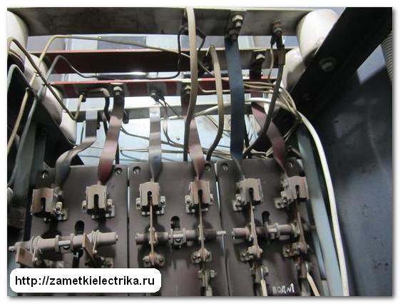
Wire-wound resistors with a rating from 5 (kOhm) to 5.7 (kOhm) are used as additional resistances. We have these resistors mounted in a housing from under.

The midpoint of the resistors is connected to one terminal of the milliammeter.
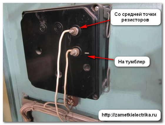
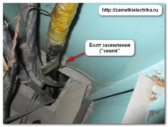
The second output of the milliammeter is connected via a toggle switch to the grounding device (“ground”) of the substation.

The operating principle of the KIZ circuit.
To better understand this diagram, let’s draw it more simplified and visually.
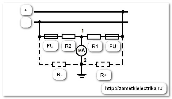
Additional resistances (R1) and (R2) form a bridge circuit with the resistances of the positive (R+) and negative (R-) poles, into the diagonal of which (points 1-2) a milliammeter (mA) is connected.
In normal mode, i.e. when the insulation resistances of the positive (R+) and negative (R-) poles are equal relative to the ground, no current flows through the milliammeter, because there is no potential difference between points 1 and 2. This state is called the balanced state of the bridge, i.e. the opposite arms of the bridge are equal: (R2)·(R+) = (R1)·(R-).
Let's assume that the insulation towards the ground has deteriorated at the positive pole, i.e. resistance (R+) decreased. This will lead to a violation of the ratios of the bridge resistance arms and will cause current to flow through the diagonal of the bridge from point 2 to point 1, at which the milliammeter is connected. The milliammeter needle will deviate towards the positive side, indicating that a ground fault has occurred at the positive pole.
And vice versa, if the leak occurs at the minus pole, i.e. resistance (R-) will decrease. This will again lead to a violation of the ratios of the bridge resistance arms and will cause current to flow through the diagonal of the bridge from point 1 to point 2. The milliammeter needle in this case will deviate towards the minus side, indicating that the ground fault has occurred at the minus pole.
Thus, according to the readings of the milliammeter needle, it is possible to determine in which of the poles the insulation has deteriorated.
The scheme under consideration is quite simple, but I would like to talk about its shortcomings. The first drawback is that if the insulation resistance is equally degraded on both poles (R+ and R-) relative to ground, this circuit will not respond in any way.
And the second significant drawback is that when a leak appears in the DC circuit, no notification signal is sent to the console to senior operating personnel. Therefore, it is advisable to use such a scheme at those substations where operational personnel are constantly on duty.
During shift inspections, operating personnel record the milliammeter readings, and if they detect a leakage current, they begin searching for the damaged line. I’ll talk about how the searches are carried out a little lower.
Let me remind you that the insulation resistance of DC buses must be at least 10 (MOhm), and secondary circuits control of drives of switches, relay protection and automation not less than 1 (MOhm): PUE, table 1.8.34 and PTEEP, table 37.
This circuit, unlike the previous one, has automatic continuous monitoring of the state of DC circuits.
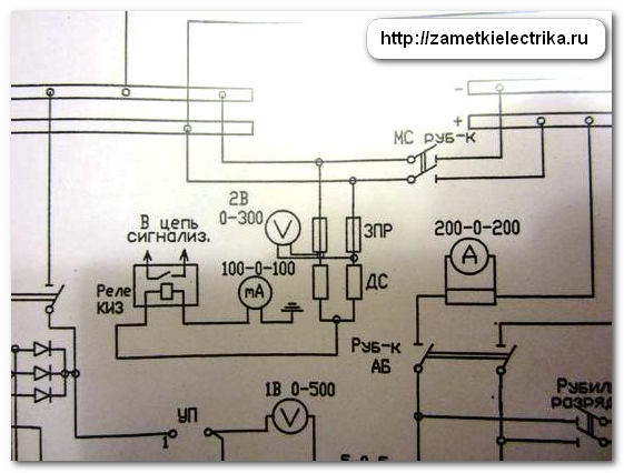
As in the previous diagram, to measure the voltage on the switchboard, an M362 type voltmeter with a limit of 300 (V) is installed.
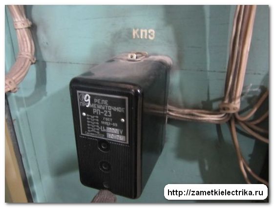
Additional resistances with a nominal value of 5.5 (kOhm) are installed in the housing of the intermediate relay RP-23.

In this circuit, a panel milliammeter of type M340 is installed. The scale has a “0” mark in the middle for measuring DC current in two directions from 0 to 100 (mA).
The circuit is similar to the previous one, only a current relay is additionally installed in the circuit, which, when a current appears in the diagonal of the bridge, is triggered and sends a signal to the warning alarm, and from there, accordingly, to the control panel for senior operating personnel.
In our case, the ETD 551/40 current relay is used as a DC insulation monitoring relay with serial connection windings with the set value 16 (mA).

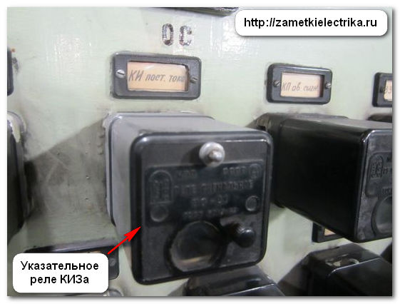
When a leakage occurs along one of the poles of a direct current greater than 16 (mA), the relay is triggered and outputs a signal through an indicating relay (colloquially called a “blinker”) to the warning circuit.
A warning signal is sent to the control panel to the senior foreman of the operating personnel.
Who and how looks for “ground” in operational DC circuits?
After receiving the signal, the duty personnel begin to search for the line where the ground fault occurred, by one by one turning off the switching devices (switches, circuit breakers, fuses, various switches, etc.) on the outgoing lines of the DC switchboard (DCB).
By the way, ground fault currents in DC circuits are small, whichdoes not cause circuit breakers to trip or fuses to blow.

The technique is as follows: the duty personnel alternately and briefly turn off all outgoing lines on the switchboard, and at the same time monitor the milliammeter. According to local instructions, it is necessary to start the search with less critical lines, for example, signaling and telemechanics circuits, and then move on to more critical connections.
When the damaged line is disconnected, the leakage on the milliammeter will disappear - it will show “zero”. After this, the relay workers begin work. Let me remind you that our relay service is included in.
If possible, the damaged line is disconnected and the location of the fault is searched. The line must be divided into separate sections and, using a megohmmeter, determine in which section the ground fault occurred. From my own experience, I will say that each case is individual, but mostly leaks occur in cable lines, on additional resistances, directly on the terminal blocks or blocks themselves, etc.
In general, I want to say that I really like finding “ground” in DC circuits. Someday I’ll write a separate post about this, if, of course, you are interested in this topic.
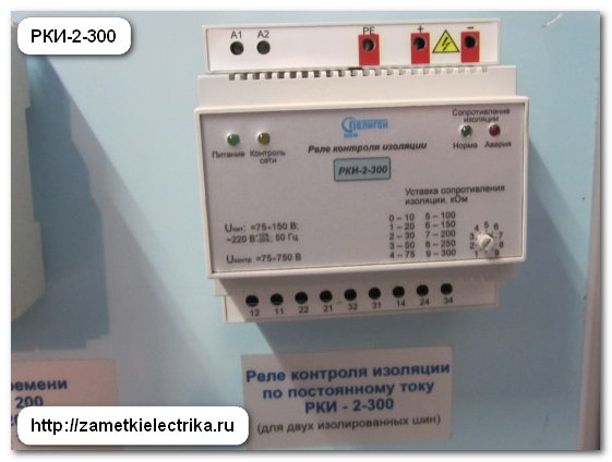
In addition to the insulation monitoring schemes discussed in the article, there are others. Also, special relay devices are currently being produced to monitor the insulation of a DC network. Here are some of them that I met at exhibitions: Skif, IPI-1M, RKI-2-300 and many others.
I haven't upgraded or changed it yet existing schemes, because There are no complaints about them, and it is not advisable to buy expensive devices with the same functionality. It is better to use free money, for example, to purchase electrical measuring instruments for ETL.
P.S. That's all. Thank you for your attention. And at the end, the question: “What schemes of critical protection operational circuits do you use?”
Hello. Today I’ll tell you about a car device that is quite useful in some cases - an inverter, which converts the on-board voltage of 12 volts DC into alternating voltage 220 volts 50 hertz.
The review contains some text, photographs of the device outside and inside, as well as oscillograms of the output voltage under different loads.
First, why is this necessary: Due to the lack of a garage, my car “lives” on the street. Because I live in the south of our country, so this is not at all terrible for the car, but sometimes there is a need to use a soldering iron, and I have a regular one for 220 volts. So you have to use various options sequential connection extension cords to carry the treasured 220 volts from the 3rd floor of the house to the car. So, in order not to suffer anymore, a low-power inverter was ordered.
Came in a paper envelope: 
 The blister is wrapped in bubble wrap, and also comes with an almost traditional gift. The packaging was practically undamaged:
 The kit consists of an inverter equipped with a connector inserted into the cigarette lighter, an adapter for different types plugs (our Soviet plugs are inserted without an adapter), as well as instructions in Chinese and English:
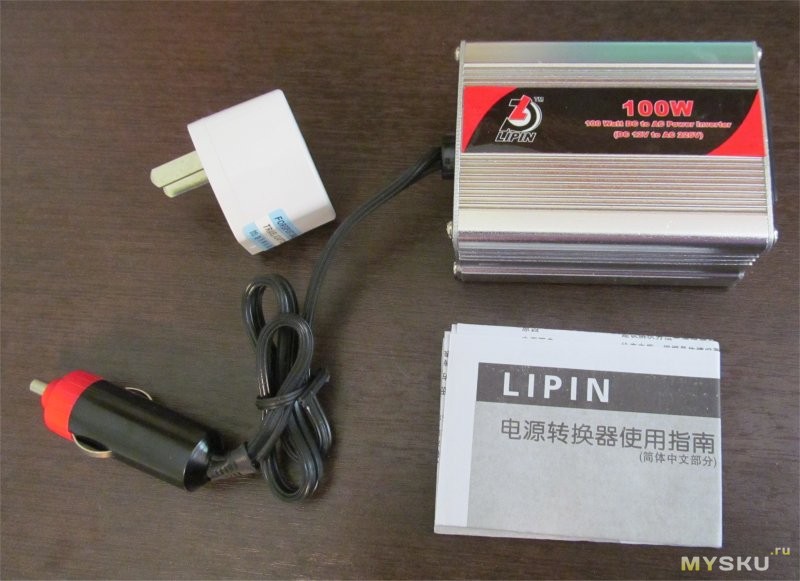
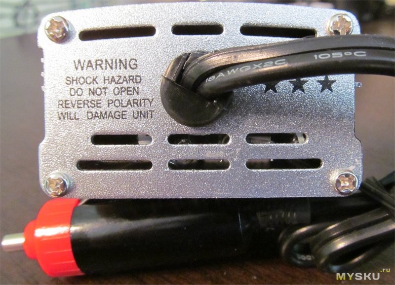
 Just a warning: the cigarette lighter connector is not equipped with a fuse, so you need to use it taking this fact into account:
 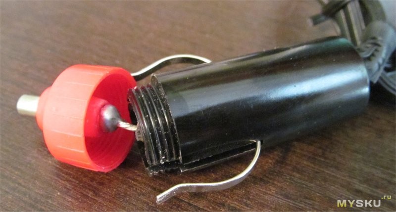 Let's take a closer look at the inverter:
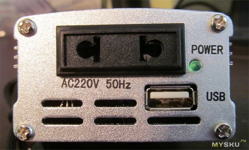
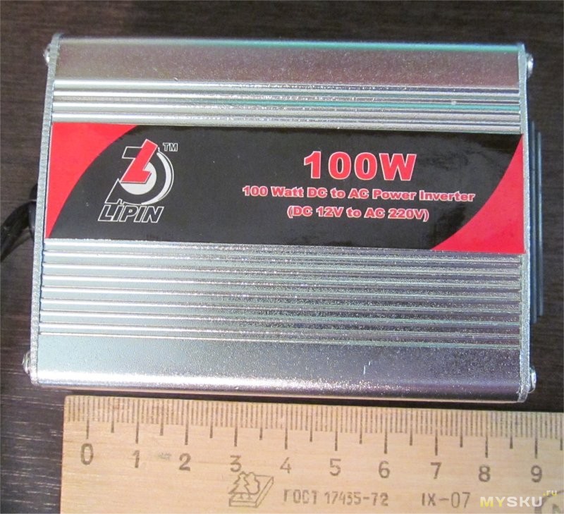 The dimensions of the device are small, approximately 9x6x5 cm. On the front panel there is a green LED indicating operation, a USB connector for charging various gadgets that allow this to be done from USB, and an output “socket” into which you can insert plugs of low-power consumers (in my case, a soldering iron and laptop).
Let's look at: 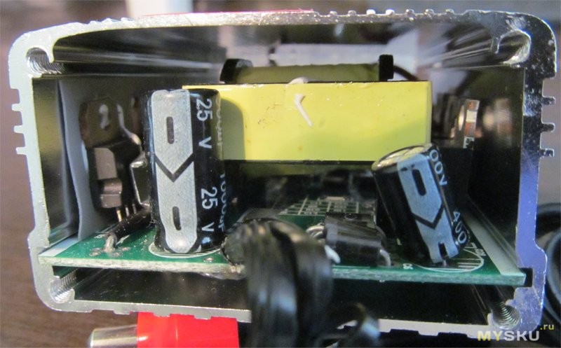
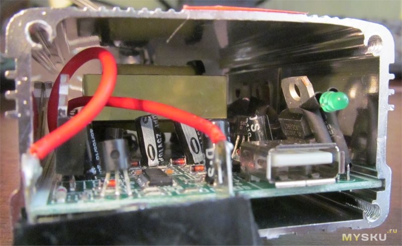 The device body is made of aluminum alloy, which also serves as a radiator for powerful transistors. You can also notice a transformer with a ferromagnetic core. To obtain the 5 volts required for the USB connector, use linear stabilizer 7805, which does not have a heatsink, so I would not recommend charging anything from this connector.
Let's see what we have at the output: 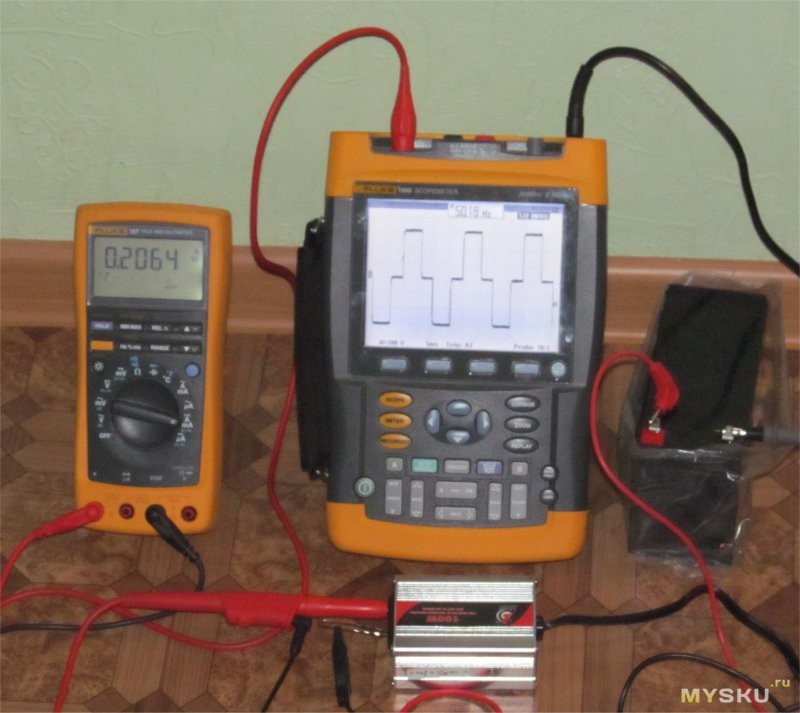
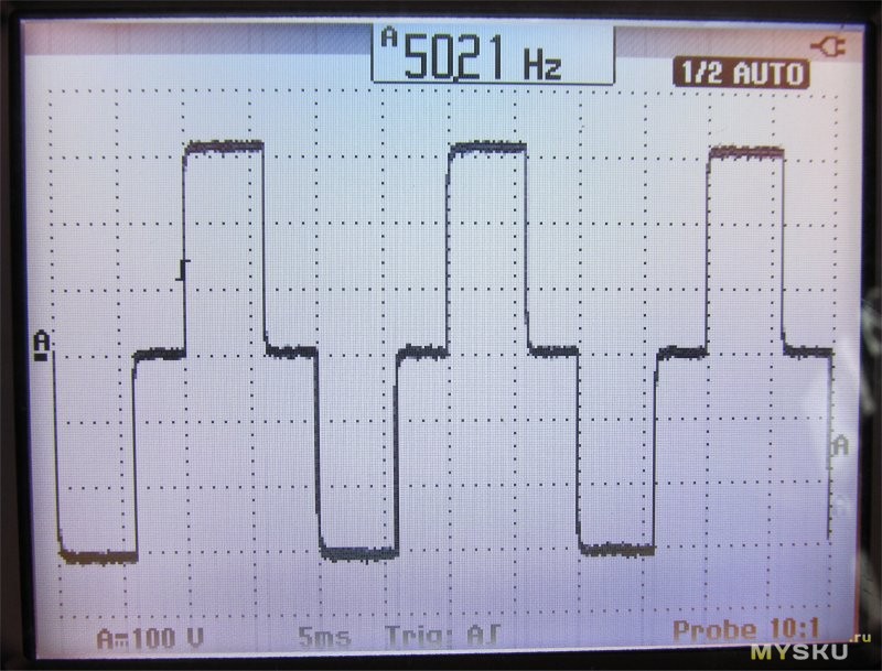 As expected, the output is not a sinusoid, but a square wave with a pause. In most household uninterruptible power supplies (UPS), the output signal shape is exactly this. UPS manufacturers call a voltage of this form “stepped approximation to a sine wave.” This shape of the curve allows, with correctly selected voltage amplitude and pause duration, to meet the requirements different loads. For example, with a pause duration of about 3 ms (for a frequency of 50 Hz), the effective voltage value coincides with the effective value of a sinusoidal voltage of the same amplitude. The amplitude value of the voltage without load is about 310 volts, which corresponds to a voltage in household network. The multimeter shows the current consumption from a 12 volt battery. That. current " idle speed"Approximately 0.2A.
Let's load the inverter with a 25-watt soldering iron: 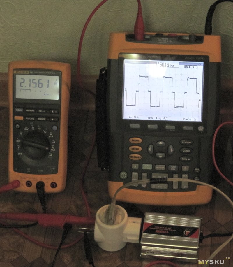 The current consumption increased to 2.2A, which is approximately 25 watts, however, the amplitude of the output voltage decreased to 250 volts, but the shape of the output signal also changed - the pauses decreased, which should compensate for the drop in amplitude. I can state that the soldering iron has heated up to the temperature required for soldering.
Let's load the inverter with a 60-watt incandescent lamp: 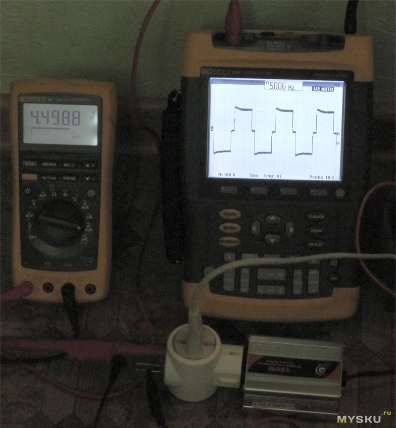 Current consumption increased to 4.5 amperes, which corresponds to 54 watts. Why not 60? Because the inverter no longer produces the required power, the amplitude voltage dropped to almost 200 volts, the pauses also decreased, but this did not help, because... The drop in lamp luminescence power compared to connection to a household power supply network is noticeable to the eye.
There was no 100-watt lamp, and there wasn’t much point. And so everything is approximately clear.
What we have as a result: A small-sized voltage converter that can be used for low-power devices: low-power soldering irons, laptops...
In principle, I am pleased with the result.
I can’t say anything about the price, because... I haven’t studied the inverter market, but this sample was provided to me free of charge by the ChinaBuye store.
Trying to repeat similar device, I came to the conclusion: the transmitter generator according to the proposed scheme does not start well. The receiver has low sensitivity, the transmitter and receiver circuits take up a lot of space using bell transformers.
The receiver and transmitter are separate units and must be located in separate housings, the insulation of which must be adequate technical specifications on safety. Based on the above, I propose my development of a transmitter (Fig. 1) and a receiver (Fig. 2).
The absence of transformers in the transmitter and receiver makes it possible to design both devices based on “double plugs”, which are plugged into 220 V network sockets. In the receiver, the necessary contacts of the executive relay are output to a separate connector or by wires.
Quenching resistors R1, R2 in the transmitter and R1, R2, R3 in the receiver must be placed on separate boards, as they heat up. In the author's version, they are located inside the “doubles” boxes, near the plugs with appropriate modifications. 4.5 mm holes must be drilled along the entire perimeter of the boxes: on the “short” sides there are 2 holes, on the “long” sides there are 3 holes for heat removal. Additional petals for mounting resistors must be built into these boxes. The transmitter and receiver circuits are mounted on separate boards and attached to the “double” housings. On each board it is necessary to provide two rectangular islands made of foil (4 pieces per board) for soldering corners with nuts to them for securing devices in boxes made of insulating materials. In the author's version, the boxes are made of one-sided foil fiberglass. The box blanks are folded inside with foil and soldered at the corners.
If installed correctly, the devices do not require adjustment. To more accurately configure the transmitter and receiver, it is necessary to use a frequency meter, an oscilloscope and a sound generator. At the same time, do not “lower” the transmitter frequency below 80 kHz, since harmonics at these frequencies interfere with television. In the original version, these devices operate at frequencies of 80-140 kHz.
The transmitter produces a signal of quite large amplitude, and even an untuned receiver “triggers” tens of meters away.
A receiver tuned to the resonance of the transmitter frequency has great sensitivity and “feels” the transmitter through several interfloor distribution boards from a different “phase”.
At the same time, the high sensitivity of the receiver leads to its operation from other sources of interference, for example, from electric welding. To reduce sensitivity in the receiver, it is necessary to reduce the capacitance of capacitor C1 to optimal, and in the transmitter, reduce the capacitance of capacitor C1 or reduce the number of turns of coil L1 in section 3-4.
Separating capacitor C1 in the receiver and transmitter type KSO-2, KSO-5 for an operating voltage of 500 V. Relay type RES34.0501, REK43.1001 for 12-14 V and an operating current of 20 mA. Resistors R1-R3 type MLT-2. The loop coil L1 of the transmitter is wound on a frame under an SB type armor core with a diameter of 22 mm, a height of 17 mm with PEV-2 wire 0.2-0.25 mm and has 75+20+60 turns.
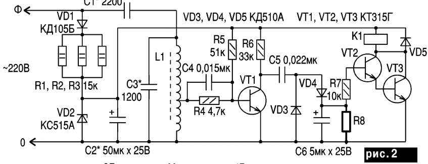
The receiver coil L1 is wound on a frame under an SB type armor core with a diameter of 17 mm, a height of 11 mm, with PEV-2 wire 0.1-0.15 mm and has 100+100 turns.
When using several devices on the same network, it is necessary to separate the frequencies of the transmitter and receiver by tens of kilohertz, and to bring the sensitivity and selectivity of the receivers to optimal levels. The transmitter power should also be increased to the required level.
When setting up the device, you must be careful, since the receiver and transmitter circuits are under a voltage of 220 V relative to ground. With appropriate modification of this device You can build a two-way speakerphone, and also use the device as a security alarm.
This device was tested in the Rajuamator laboratory, since it uses a life-threatening alternating voltage of 220 V.
Literature: 1. Vesnin Yu. G., Anisimov N. V. Reference book transistor radios, radios and tape recorders. - Kyiv: Tekhnika, 1986.