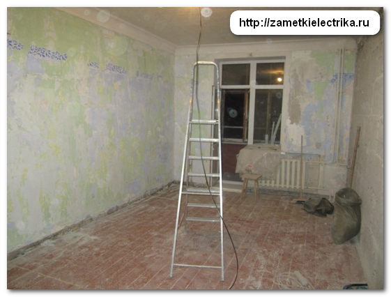
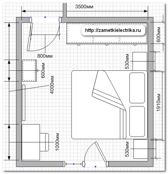
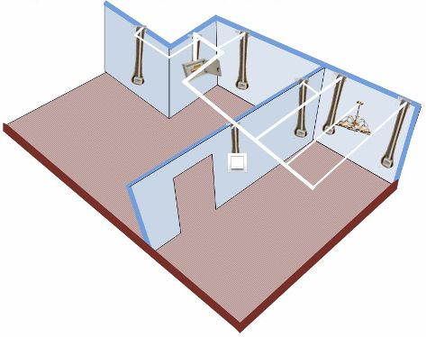
In general, we have this small bedroom with an area of about 14 sq.m. Here is the floor plan of its premises.
Using this bedroom as an example, I will show you how to lay cable lines, in what places and at what height to install sockets and switches, and other nuances.
Having studied all the information, you, in principle, will be able to do the electrical installation yourself, or, at least, supervise the work of hired electricians.
So, let's go.
And by tradition, I repeat. Before starting installation work, you need to draw up a plan for the arrangement of furniture in the bedroom, and for this you need to do your best, literally “extort” from the customer what and where he will have it installed, and preferably with overall dimensions. I understand perfectly well that at this stage repairs are not so easy to do, because... As the renovation progresses, preferences and furniture layout may change.
It’s another matter when you have in your hands an approved and agreed upon by the customer finished project, however, not all customers, especially in small provincial towns, will do an electrical wiring project for a 1, 2 or 3-room apartment at the cost price of installation work. Here, most likely, you will be both an installer and a designer rolled into one!
Furniture layout in the bedroom
For clarity, I numbered each wall in the bedroom and displayed the numbers on the plan.

A wardrobe will be installed near wall No. 1 from the doorway to the very corner. There will be no sockets or switches installed on this wall.

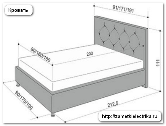
The end of the wardrobe will be adjacent to wall No. 2. Also, against wall No. 2 there will be a double bed with two bedside tables.

The width of the cabinet is 60 (cm), so we immediately measure this distance from the corner of the wall. Then we retreat from the cabinet about 20-30 (cm) and mark overall dimensions first cabinet (stand No. 1).
Cabinets can be of different widths, but their average height usually does not exceed 50-55 (cm). But in order not to make a mistake, it is still better to know exactly the specific model of the cabinet.
In my example, the width of the cabinet is 53 (cm) and the height is 52 (cm).

After bedside table No. 1 there is a double bed, which has a width of 191 (cm).
After the bed, a second bedside table will be installed (bedside table No. 2).
As a result, we received the following layout of wall No. 1 and wall No. 2.
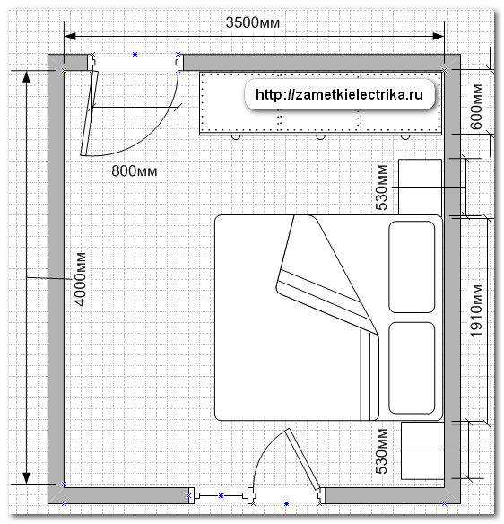
Wall No. 3 is a wall with a balcony block. In principle, there are no plans to install anything on it. True, initially there was an idea to install a switch on it to illuminate the balcony, but this idea was soon abandoned, because... The window is large enough and there is enough light from the room to illuminate a small balcony.

And we still have wall No. 4.

Adjacent to it will be a computer desk measuring 50x100 (cm), a small chest of drawers 40x80 (cm) and a TV (on a wall-mounted bracket).
This is how the bedroom plan turned out with all the furniture arranged and now you can safely move on to drawing up the electrical wiring plan.
Wiring diagram in the bedroom
We will draw up an electrical wiring diagram, displaying on the floor plan all sockets, switches, lamps, distribution boxes etc., as well as routes for laying cable lines.
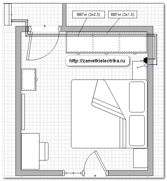
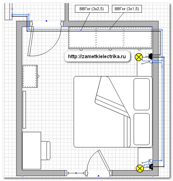
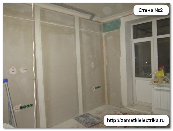
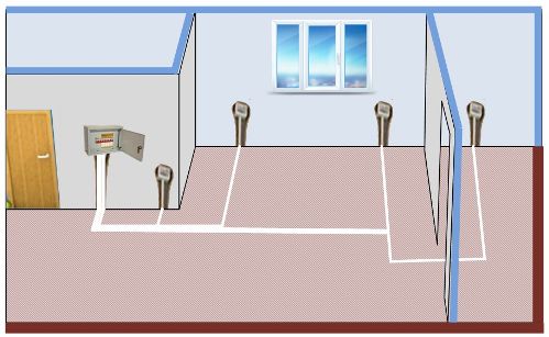
Let's start with wall number 2.
The following electrical installation items (points) will be installed above each cabinet at a height of 60 (cm) from the finished floor:
- socket (single), for example, for charging cell phone, tablet and other needs
- single key switch for wall sconce
- pass-through (or cross) switch of the 1st group of bedroom lighting
- pass-through (or cross) switch of the 2nd group of bedroom lighting
The socket of cabinet No. 1 is powered by a VVGng cable (3x2.5), and the lighting lines for wall sconces are supplied by a VVGng cable (3x1.5).

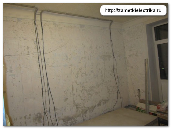
The cables are laid along the ceiling in plastic corrugation with a diameter of 16 (mm) and 20 (mm), and are attached to it using plastic clips. By the way, the ceiling in the bedroom will be suspended.


I have already repeatedly cited the requirement of SP 31-110-2003 (clause 14.15) that electrical wiring behind a suspended ceiling when using VVGng cable must be made in plastic corrugation. If you don’t want to bother with corrugation, then you can use cables with reduced gas and smoke emissions, for example, VVGng-LS or another similar one.


This is what it looks like on the plan.
Yes, by the way, the electrical wiring in this apartment is made without junction boxes. About the advantages and disadvantages this method I talked in detail in a separate article (), so I won’t dwell on it now.
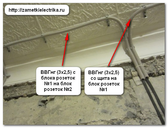
A VVGng cable (3x2.5) is laid from the socket of cabinet No. 1 to the socket of cabinet No. 2, i.e. a jumper is made between these two sockets.
In the same way, only from single-key switch sconce of cabinet No. 1, the supply cable VVGng (3x1.5) is laid to the single-key switch of sconce of cabinet No. 2.


From each single-key switch of cabinet No. 1 and cabinet No. 2, a VVGng cable (3x1.5) is laid, respectively, to the installation location of the sconce.
Every wall lamp(sconce) will be controlled only by its own.

Typically, sconces are installed at a height of 130-160 (cm) from the floor level, although again this all depends on the specific conditions of the customer. The installation height of the sconce in my case is 140 (cm) from the finished floor.
The socket line is protected by an automatic rated current 16 (A) and a group RCD with a leakage current of 30 (mA), and the lighting line for wall sconces - with an automatic 10 (A) and a group RCD with a leakage current of 30 (mA).
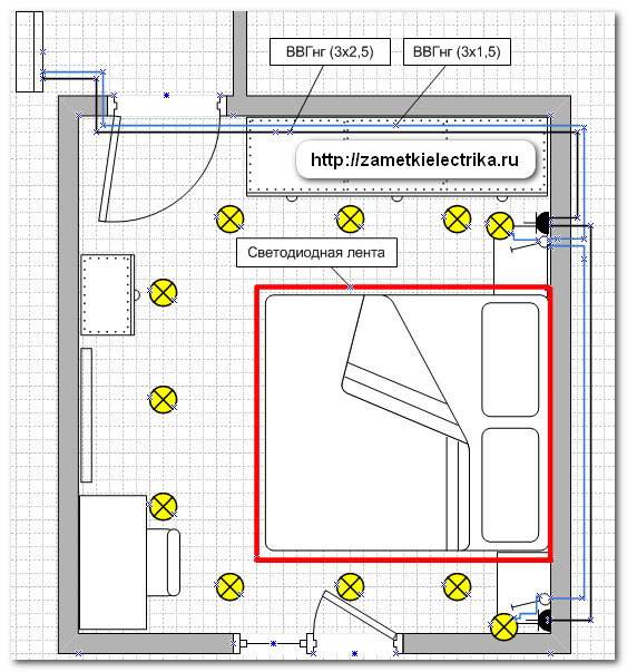
As the 1st group of bedroom lighting is general lighting in the form of 9 ceiling spotlights, and as the 2nd group - an LED multicolor RGB strip in a niche on the ceiling (on the plan there is an outline in the form of a red rectangle), which I already told you very much about.
According to SNiP 23-05-95 “Natural and artificial lighting"(Appendix G and Appendix I, clause 63), the illumination in the bedroom should be in the range from 100 (Lx) to 150 (Lx).
The required illumination can be easily achieved by uniformly installing 9 ceiling lamps, and this will even be with a reserve, besides, the room has LED backlight on the ceiling and two wall sconces.
The lighting in the bedroom will be controlled from three places: at the entrance to the room and at each bedside table. Therefore, at the entrance to the room there will be two single-key pass-through switches (GSL000161), at cabinet No. 1 - two single-key cross switches (GSL000171) and at cabinet No. 2 - two single-key pass-through switches (GSL000161).
Personally, it’s more consonant for me to call switches switches, because... I don’t see much difference in this case between these values. Therefore, further in the text I will use the term “switches”.
To reduce the number of switches, it would be possible to use two-key switches instead of single-key pass-through and crossover switches, but I did not find two-key crossover switches in the Glossa series from Schneider Electric in the catalog. There are two-key pass-through switches (GSL000165), but there are no two-key cross switches.

I even created a separate topic about this on my Electricians Forum (link to it in the top menu of the site) and they told me that Schneider Electric has such switches, but only in other series. But this option was not suitable for me, because... In the apartment, all electrical installation products were planned to be installed in the Glossa series.

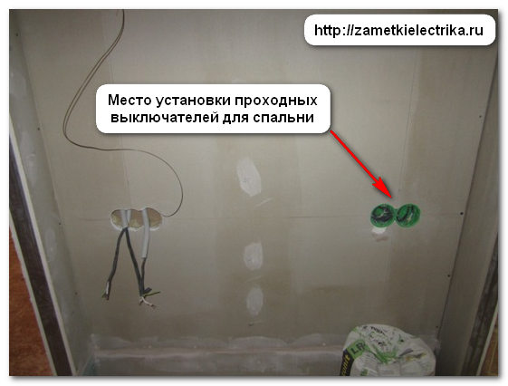
Pass-through switches at the entrance to the bedroom are installed not inside the room on wall No. 1, as is usually done, but on the side of the corridor. Yes, I agree that in rooms, switches are usually installed inside so that you can control the lighting of the room without leaving it, but in our case the bedroom lighting is controlled from as many as 3 places, so this is not important here, besides, in this case it will remain a little more space for a wardrobe.
Pass-through switches are installed at a height of 90 (cm) from the finished floor and 15-20 (cm) from the doorway, or rather the corner. Remember, I already said in one of the articles that if the switch is installed more than 25 (cm) from the doorway, then it will not look very nice and, as it were, separately from it. Here on this wall there are two more switches: a single-key switch for lighting control next room and a passage for the corridor. Therefore, all switches look symmetrical and quite aesthetically pleasing on this wall.
Lighting of the bedroom and the adjacent room is carried out using a VVGng cable (3x1.5) from the apartment switchboard.
First, the VVGng cable (3x1.5) goes into the socket box of the single-key switch in the next room, and from there a jumper is made with the VVGng cable (3x1.5) into the socket box of the pass-through switches in the bedroom.

Then with pass-through switch The 1st group (general lighting) cable VVGng (3x1.5) goes to the cross switch of the 1st group of cabinet No. 1. From the pass-through switch of the 2nd group (LED backlight), the VVGng cable (3x1.5) goes to the cross switch of the 2nd group of cabinet No. 1.
![]()
![]()
Then, from the cross switch of the 1st group (general lighting) of cabinet No. 1, the VVGng cable (3x1.5) goes to the pass-through switch of the 1st group of cabinet No. 2. From the cross switch of the 2nd group (LED lighting) of cabinet No. 1, the VVGng cable (3x1.5) goes to the pass-through switch of the 2nd group of cabinet No. 2.
4 cables come to cabinet No. 1 and 4 cables go out, i.e. There are only 8 cables, including the sconce power cable.


Next, from the pass-through switch of the 1st group (general lighting) of cabinet No. 2, the VVGng cable (3x1.5) goes to the first ceiling lamp, and then all ceiling lights connected to each other by a cable. From the pass-through switch of the 2nd group (LED backlight) of cabinet No. 2, the VVGng cable (3x1.5) goes to the power supply of the LED strip.

4 cables come to cabinet No. 2 and 2 cables go out, i.e. There are only 6 cables, including the sconce power cable.
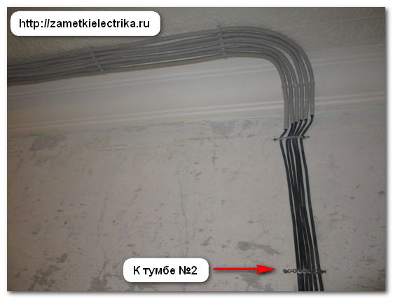

This is what wall #2 looks like after all the cables have been laid.


At the time of installation, I still did not know how exactly the lighting would be done in the bedroom, so I first brought the cables of the 1st and 2nd groups to the center of the room, as can be seen from the photographs above. And a little later it became known that the 1st group will be general lighting for the bedroom in the form of 9, and the 2nd group will be LED lighting.

And now we will transfer everything said above regarding wall No. 2 to the bedroom floor plan in the form of an electrical wiring diagram.

The line of the 1st group and the 2nd group of bedroom lighting, as well as the lighting line of the next room, are protected by a 10 (A) circuit breaker and a group RCD with a leakage current of 30 (mA).
Let's move on to wall No. 4.
It is planned to install the following electrical installation products (points) on wall No. 4:
- socket block No. 1 for various needs
- socket block No. 2 for TV
- socket block No. 3 above computer desk
- socket block No. 4 under the computer desk
Power supply for socket block No. 1, intended for other various needs (switching on a vacuum cleaner, floor lamp, etc.), is carried out by a VVGng cable (3x2.5) directly from the apartment panel.
Socket block #1 includes two regular sockets. The installation height of this socket block is 30 (cm) from the finished floor.
Before planning the placement of a particular electrical installation point (socket, switch, dimmer, etc.), you need to know the door opening direction, because in the absence of such information, you can make a mistake and install sockets or switches, for example, behind the door, which will not be convenient to use in the future.
In our example, the bedroom door will open onto wall No. 4. The door has a width of 80 (cm), which means we need to retreat about 100 (cm) from the corner of the room so that the door does not obscure the sockets when opening.
From the socket block No. 1, the VVGng cable (3x2.5) supplies power to the socket block No. 2 for the TV.
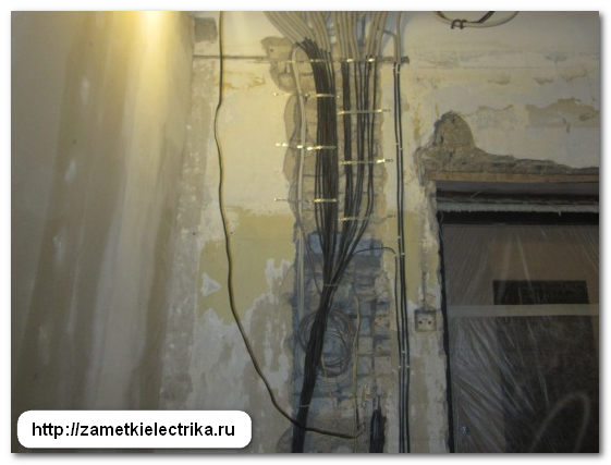
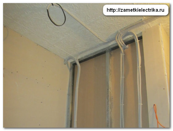
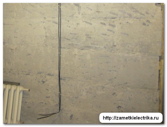
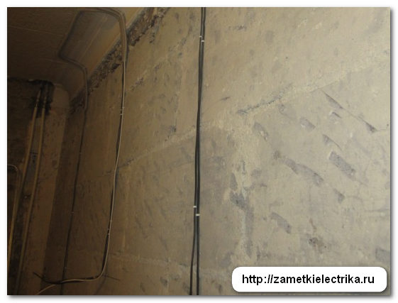
Unlike wall No. 2, I secured the cables using plastic dowel clamps at a short distance from each other.

Let me remind you once again that the electrical wiring in this apartment is made completely without distribution boxes, so the connection of the power cable with the cable of the subsequent outlet will be carried out in the socket of this very outlet. The connection will be made via a loop, but without disturbing PUE requirements. There will be a separate explanatory article about this soon, so subscribe to the site’s newsletter so as not to miss anything interesting.
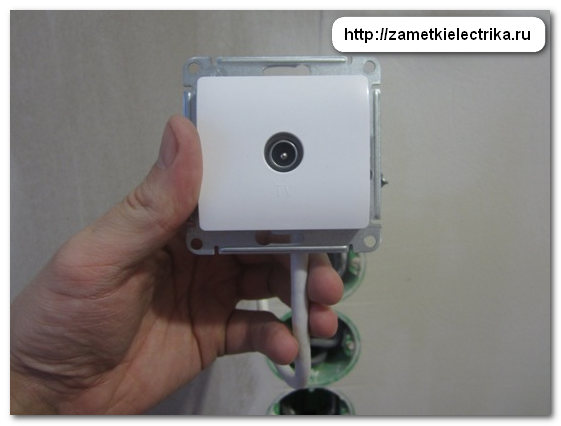
TV socket block #2 includes two regular sockets and one TV socket.
The installation height of the socket block No. 2 for the TV is about 150 (cm) from the finished floor. It makes no sense to install sockets above this level, because... You will have to lift your head up a lot when watching TV while lying down. Although here, again, it is better to check with the customer, otherwise lately TVs began to be installed even on the ceiling.

The TV outlet is powered directly from the apartment low-current switchboard using an RG-6U cable.

From the socket block No. 2 for the TV, the VVGng cable (3x2.5) supplies power to the socket block No. 3 above the computer desk. Socket block #3 includes three regular sockets. This is very convenient, especially for various devices frequently connected (disconnected) to the socket. There is no need to bend over and crawl on your knees under the table every time.
In my case they will be connected desk lamp And chargers various gadgets.
The installation height of socket block No. 3 is 90 (cm) from the finished floor. This is quite enough, because majority standard tables has a height of no more than 70-80 (cm). If the table is not standard, be sure to check its height.

From the socket block No. 3, the VVGng cable (3x2.5) supplies power to the socket block No. 4 under the computer desk. Socket block No. 4 includes three regular sockets and one Internet socket. The laptop power supply, printer and small active speakers, as well as the Internet network for the laptop will be connected here.
The Internet outlet is powered directly from the apartment low-current switchboard using a UTP cable where the router is installed. I will write a separate article about the Internet socket in the near future and tell you in detail how it is connected and installed.
The installation height of socket block No. 4, as well as socket block No. 1, is 30 (cm) from the finished floor.

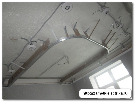
This is what wall #4 looks like after all the cables have been laid.


And this is how it will look on the plan.
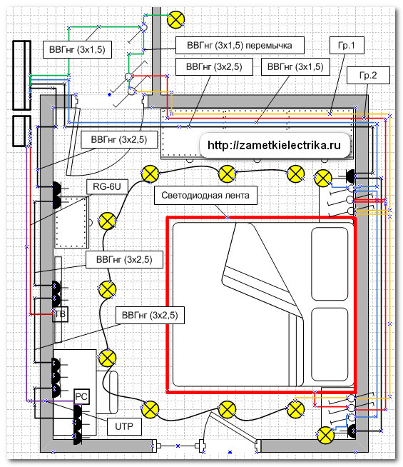
The socket line of wall No. 4 is protected by a 16 (A) circuit breaker and a group RCD with a leakage current of 30 (mA).
At this stage, my work was over and the builders got to work.
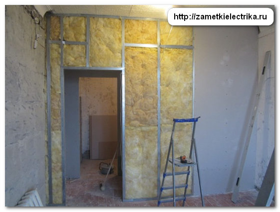
To level walls No. 2, 3 and 4, the builders decided to use drywall. But in order not to reduce the volume of an already small room, they decided to attach the sheets of drywall without using metal profiles, and with the help gypsum glue"Perlfix GF" (Knauf), thereby gluing sheets of plasterboard directly to the walls and leveling them.

This is what happened after installing the drywall.

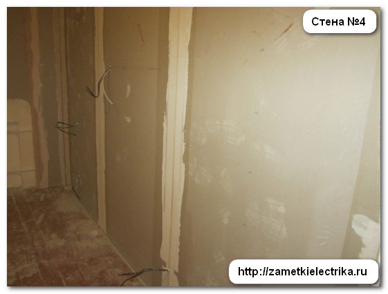
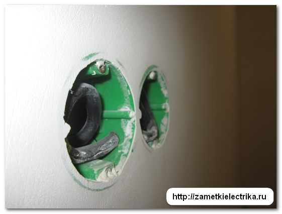
After that I started installing the socket boxes.
I have a separate detailed article about that, so I won’t dwell on it now.


![]()
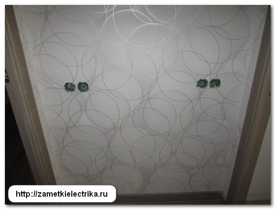
At this point, the rough installation of electrical wiring was completed. After this, the builders got down to business again, starting finishing walls The result is like this.


After that, the builders were busy gluing wallpaper, laying laminate flooring, installing interior doors etc.


In addition to the work of builders, specialists stretch ceilings The ceiling was installed in the bedroom.

And now it’s my turn to do the finishing touches. How to install this or that mechanism (sockets, switches, pass-through or cross switches, TV sockets, Internet sockets, ceiling lamps, wall sconces etc.) there will be separate articles. Once again I remind you, so as not to miss new issues of articles, subscribe to the site’s newsletter.
And at the end of the article I present to your attention the material of the entire article in video format:
Living spaces for people are constantly being improved. They appear more and more electrical appliances, improving life. Electricity consumption increases, and the wires laid during construction are exhausted: metal and insulation age, losing properties from overloads, heating, ultraviolet radiation and mechanical influences.
Operated since USSR times aluminum wiring has been in need of replacement for a long time. Increased safety requirements have been lifted TN-C system, which did not provide for grounding the housings of electrical appliances, the use of a potential equalization system, or protection against leakage currents.
Owners of old apartments do not always imagine how wires are placed in their premises, because there are many options for laying them.
Types of schemes
The main classification of electrical wiring is carried out according to the type of installation:
open;
closed.
The first method allows you to visually observe the passage of the routes. It is more affordable and is most often used in wooden houses.
It is more difficult to detect wires hidden in walls, floors or ceilings: they are not visible. They were laid differently in each building, but principles can be identified that take into account the construction period, wall materials, and installation technologies.
Aluminum wiring studio apartment
This scheme is common, has been used for a long time, is well suited for a larger number of premises, and is easy to understand and implement.
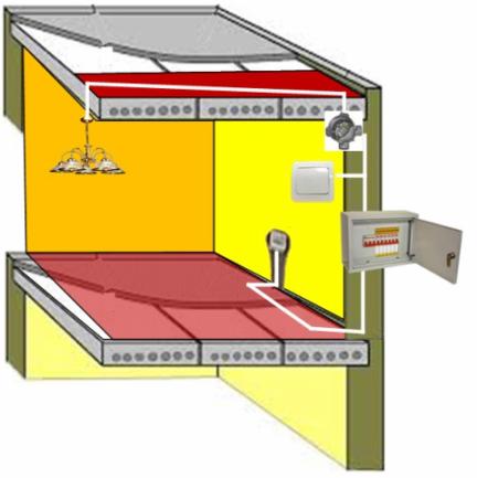
In old houses on each floor there is electrical panel with a meter, a packet switch to relieve tension when working with metering devices and circuit breakers. All equipment is sectioned for each apartment separately.
![]()
Rice. 1. Option old electrical wiring studio apartment
For clarity, the picture shows two distribution boxes in each room, but, most likely, the circuits of sockets and lighting are switched through one.
There is no grounding loop provided here. The circuit uses exclusively zero and phase, and neutral wire should never be interrupted by switching devices anywhere. It is supplied directly to all consumers through distribution boxes, and is taken from the meter.
To connect the wires, most likely, simple twists with or without welding are used, although screw terminal blocks may be found. The most wires go to the place where the zero is assembled.
The phase from the meter goes to the circuit breakers. In our example, one powers all the outlets, and the other powers the room lights. If the apartment is equipped with an electric stove, then the voltage is supplied to it through a separate circuit breaker, and the wires are used with increased power: up to 10 mm 2.
Variations of the scheme are possible:
used instead of machine guns;
When installing wires after the meter, electricians confused the phase directions with zero (the circuit does not lose its functionality, but is more dangerous);
a group of machines has been added and consumers are powered according to a different scheme, for example, for a corridor.
Each specific circuit should be carefully understood; it is quite possible that there will be jumpers, additional wires, or even installation without junction boxes.
A simple method helps to understand the principle of circuit design:
turn on all lighting devices and plug in electrical appliances;
turn off consumers one by one using automatic circuit breakers in the distribution panel and observe the extinguished lamps and switched off devices in the sockets;
analyze changes, write down or remember information, draw conclusions.
Types of hidden wiring
In practice, highways are laid:
on or inside the ceiling;
under the floor;
combined.
Wire layout inside the ceiling
It was previously widely used in buildings made of brick and concrete panels as the main wiring option. IN modern construction it is also often used.
All routes with wires from distribution panel are directed vertically over the wall or inside it through grooves or built-in pipelines. The insides of ceiling tiles are usually made with channels for wiring, but grooved or suspended installation is allowed for suspended and suspended ceilings.
In the same way, the supply to the lamps, all switches and electrical outlets located on the walls.
Rice. 2. Option for wiring inside the ceiling
With a competent approach to installation, all wiring is oriented in perpendicular planes: this eliminates damage to the insulation and metal during future drilling of walls to secure various objects to them. Horizontal lines from the ceiling cannot be lowered below 15 cm for the same reasons.
Distribution boxes are attached to their circuit breakers to supply voltage to the nearest point. Installation in them is carried out according to wiring diagrams.
Layout of wires under the floor
This option began to be used in new buildings with hard concrete base and creating durable pipelines from pipes under the floor covering, followed by filling with solutions. Such measures reliably protect the insulation and metal from mechanical damage.
Cables and wires in the walls for sockets and lamps are protected by pipes or.
Rice. 3. Option for laying electrical wiring under the floor
Combined wire placement methods
Both described methods are combined here, but such schemes have many individual nuances.
Factory-built panel houses
They have the insides of wall and ceiling slabs made with channels for laying electrical circuits. The routes connect all electrical consumers through distribution boxes with an input panel. Wires are pulled into these lines.
Please note that here the pipes may not be located at straight angles, but at sharp angles. Their location can only be determined.
Rice. 4. Option for old electrical wiring in the apartment
Houses built during the Khrushchev era
In old panel buildings, they used a rather simple placement of wiring, which significantly reduced the construction technology, but was far from safe.
“Aluminum noodles” are supplied to the sockets under the boards of wooden flooring, and comes down to the lamps from under the floor upper neighbor through a hole in the ceiling slab. This is the most dangerous installation, which usually has no protection. Here twists without welding are often found, and the insulation begins to deteriorate.
Such wiring must be completely redone, but this is a complex and expensive undertaking.
Each of the considered schemes may have various deviations from the project, even in neighboring apartments of the same building. A specialist can identify them by carrying out electrical measurements. This work is often performed under voltage, which is dangerous.
Therefore, without a solid knowledge of safety rules and practical skills in working with electrical appliances, it is better not to undertake the independent refurbishment of your apartment.
Let's look at connection methods electrical circuit.
Parallel connection- with this method, the elements included in the circuit are combined by two nodes and are not connected to each other (Fig. 6.4). With this connection of the elements, even if one of the lamps burns out and breaks the circuit, the others will not go out, since the current will have “bypass” paths.
Serial connection- all elements of the chain are located one after another and do not have nodes (Fig. 6.5). Example serial connection- the well-known Christmas tree garland: large number light bulbs connected by one wire. If one burns out, the circuit will break and all will go out.
There are three main types of wiring connections. Let us consider them in detail, since the entire scheme depends on the selected type.
1. The star type is sometimes called the boxless, or European, type of wiring. Briefly this type can be displayed like this: one socket - one cable line to the panel. This means that each outlet and lighting point has a separate cable line, which goes directly into the apartment panel and ideally has an automatic switch.
What are the advantages and disadvantages of this type of connection? The advantage, first of all, is safety and the ability to control every electrical point. In addition, there is no need to install distribution boxes. This type of connection is made when installing the system " smart home" The downside of the “star” is at least three times the wiring consumption and, accordingly, the labor costs for its installation. In addition, the apartment panel becomes the size of an average closet. It can consist of 70-100 groups of machines, especially if the facility also has information networks. It is difficult to install such a shield yourself, and it is more expensive than a regular one.
3. Type of connection in junction boxes- the most common option (Fig. 6.7). This is exactly how the wiring was done in Soviet era. An economical way that does not require special costs. There is no shield at all in the apartment; it is located on landing. From such a common supply “riser” there is an apartment branch. On it in the shield they stand
Sockets connected by a "loop" meter and circuit breaker (sometimes - 1, sometimes - 2-3, rarely more). The power cable enters the apartment, then, using distribution boxes, into the premises, approaching each point. We can say that from the junction box the wiring goes to the points in a “star”.
Pure wiring types are rarely used. Based on the available resources and at will, a mixed type is usually selected. Let's give an example of wiring in separate apartment(Fig. 6.8). 
The power cable goes into the apartment panel, where there are several groups of circuit breakers and protection devices. In the panel, the common cable is routed into several zones, for example living rooms and separately for the bathroom and kitchen with division into sockets and lighting. Power cable separate zone enters the room and disconnects in the box point by point. Options are possible here: the cable will go to the sockets in a “loop” or a separate conductor will be allocated to each point.
Another possible option(parallel circuit)
For example, the owner says that in the living room there should be two groups of sockets, three in each. Plus two pass-through switches and three telephone sockets. The electrician, having taken into account these data, according to the rules of electrical installation work, draws up a diagram that takes into account safety parameters, the order of work, the type of wiring, the dimensions of the grooves, etc. Such a drawing is a document and is certified by a special organization (Fig. 6.10).
Modern companies providing services electrical installation work, enjoy computer programs(Fig. 6.11). They are created specifically for engineering and technical workers (E&T) and home handyman are unlikely to be useful.
To install the wiring yourself, you can draw the diagram yourself. This is done quite simply. To begin with, an apartment plan is drawn taking into account all sizes. If not necessary documentation, you can take it from the developer, although it must also be kept by the owner of the property.
Then, using special symbols, all the desired points are set: lamps, sockets, circuit breakers, etc. (Fig. 6.12). We must not be lazy and put in generally accepted notations so that other people can understand this diagram. There are frequent cases when, some time later, the author of the diagram cannot understand the mysterious hieroglyphs that he himself invented.
After this, lines are drawn that indicate the wiring. Be sure to indicate on the plan how far the cable is from the ceiling or floor, especially if the wiring is hidden.
The following is an example electrical diagram apartments (Fig. 6.13). Different colors lighting wires are shown, power cables and ground wire. Conventional icons depict lamps, sockets, switches and distribution boxes. This diagram is very visual, and you can use it to perform all the necessary calculations.

This is necessary in order to know exactly where the wires go in the future. Otherwise, while hanging a picture or shelf, you can hit the cable with a drill. There are standard rules for installation. They are like that.
1. The wire is laid only along vertical and horizontal lines at right angles. If you want to cheat and save the cable by running it diagonally, it is better not to do so. In the future, it is very difficult to find this crooked path, and hitting it with a nail is as easy as shelling pears.
2. The distance from the wire to the ceiling or floor should be 15 cm. From the corners, door jambs And window frames- at least 10 cm. When piping through heating pipes, a gap between them and the wiring should be at least 3 cm (Fig. 6.14).
3. It is necessary to avoid crossing wires when laying. If this is difficult to achieve, then the distance between the cables should be at least 3 mm.
4. To simplify calculations, all sockets and switches must be at the same height. Typically, switches are installed to the left of the door at a height sufficient to touch them with a lowered palm, that is, 80-90 cm. Sockets are mounted at a height of 25-30 cm. However, in the kitchen and in the case of connecting high-hanging electrical appliances, this distance can be and others. It is best if the wire to the switches goes down from above, and to the sockets from below, which is what most electricians do.
5. The length of the conductor coming out of the electrical point should be 15-20 cm. This is done for the convenience of installing points with a hidden type of wiring. If she open type, then the length of the conductor may be less: 10-15 cm.
ATTENTION!
The ends of the conductors that go into electrical points, must be insulated with electrical tape.
Armed with the drawing, you can begin to install the electrical wiring.
The modern electrical wiring plan for a two-room apartment differs in many respects from previously used diagrams. The fact is that modern loads are simply incommensurate with the loads of the 70s and 80s, when most panel houses were built.
Back then, the main consumers were a few light bulbs, a TV and sometimes an iron. Modern apartment has significantly more electrical appliances and, accordingly, needs other power supply schemes.
Choosing a method for laying electrical wiring in an apartment
Open wiring
So:
- Before developing a wiring plan in two room apartment, we need to decide on its main parameters. One of these is the method of laying it. On at the moment two options are used - open and hidden.
- Open wiring has certain advantages:
- To install it, there is no need to trench the walls. That is, you can completely replace all wires without subsequent repairs throughout the entire apartment.
- Mounted open wiring very quickly. And with the proper skill and availability of workers, it can be completely installed in literally a day.
- If you need to connect new electrical receivers or carry out repairs, you do not need to break down the walls.
- Installation hidden wiring carried out in special boxes. In this case, the wire in the boxes usually has additional protection in the form of metal or self-extinguishing corrugated pipe. You can, of course, install it without using special boxes, but this option is more suitable utility rooms and sheds, but not apartments.
- Branches to sockets and switches are also made using a special box. And the sockets and switches themselves must be designed for an open circuit.
- The wiring diagram can also be used in two-room apartment with its installation in baseboards. But this method has significant limitations on the number of wires used and is often used only for wiring separate rooms or for laying to individual electrical receivers.

Hidden wiring
So:
- More common is the wiring diagram in a two-room apartment using hidden electrical wiring. This method has the following advantages:
- Due to the fact that all elements of such wiring are hidden from prying eyes, it has a more attractive appearance
- Doesn't take up free space in our already small apartments
- Hidden wiring has higher throughput and overload capacity due to better heat transfer.
- Due to lower requirements for protection from mechanical damage, the price necessary materials noticeably lower.
- Installation of hidden wiring is carried out directly in the structural elements of your apartment. To do this, small recesses are made in the wall - grooves. Wiring is laid in them, followed by plastering.
- To install sockets, switches and distribution boxes, recesses are also made in the wall. They are then installed with sockets and switches designed specifically for the hidden circuit.
Calculation and selection of power supply scheme
Posting calculation
So:
- Before we begin directly calculating our electrical wiring, we need to decide on the number of electrical receivers. To do this, it is necessary to accurately determine the number and location of each outlet and lamp. Without this clear plan, further calculations are impossible.
Pay attention! You should not deliberately overestimate the number of outlets or lighting you require. You only need those outlets to which you know exactly what will be connected. Installing sockets and lighting circuits just in case greatly increases the cost of your electrical system and increases your labor costs.
- Now having a clear idea of the number of electrical receivers, we can proceed directly to the calculations of the required wire. But throughput wires in clause 1.3 of the PUE (Electrical Installation Rules) are indicated in amperes, and the power of all our devices is usually indicated in watts.
- Using Ohm's law, which everyone should know from school, we perform a recalculation: where P is the power of the device in Watts (W), U is the voltage of your electrical network in volts (V), for single-phase network the voltage is 220V, and I is the current that will flow in the wires in amperes (A).

- Having made a simple calculation, we find that when connecting a 1000W device, a current of 4.55A will flow in our wire. Our instructions advise rounding this value to 5A to create a certain margin and simplify calculations.
- Now let's start choosing the wire. It can be made of copper or aluminum and is insulated with polyvinyl chloride or rubber. The choice should be made in accordance with clause 1.3 of the PUE. It includes a conductor depending on laying conditions, insulation, humidity and some other parameters.
- But all this is quite complicated and light loads apartments is not always justified. Therefore, if you are not a design office and are replacing the wiring yourself, then we advise you to use a simplified calculation. According to it, a copper wire with a cross-section of 1 mm2 in normal mode passes a current of 10A, and aluminum wire with the same cross section - 5A.
Selecting a wiring diagram
So:
- Having calculated all possible loads, we should divide them into groups. In this case, we will be guided by clause 6.2.2 of the PUE, which states that group lines must be protected by circuit breakers for a current of no more than 25A. At the same time, if you create a separate group for the lighting network, then it will usually be equipped circuit breaker at 16A.
- When dividing the load into groups, the power of consumers should be taken into account separately. These include electrical equipment with a power of 2 kW or more. These are usually heating and heating devices. If you have any, then they should be powered by a separate machine with the appropriate rated current.
- Without taking into account powerful consumers, your wiring plan for a two-room apartment should have two to three groups. One of which is the lighting network and one or two groups are power sockets.
If you have two groups powering the sockets, then it is advisable to form groups in adjoining rooms. That is, one group powers the sockets in the kitchen and hallway, and the second - in the bedroom and living room.
Pay attention! According to clause 7.1.37 of the PUE, installation of sockets in the bathroom is permitted only when connected through an RCD. If you are installing an outlet in the bathroom, it is advisable to include it in the group that powers the kitchen outlets. After all, although sockets are not required in the kitchen mandatory installation RCD, this device protection in the kitchen would be most appropriate.
- Separately, I would like to dwell on the cross-section of the wires used. For groups with a 25A circuit breaker, the copper wire must have a cross-section of at least 2.5 mm 2.
Accordingly, for groups of 16A, at least 1.5 mm 2. But in any case, the cross-section of the wire feeding a separate group is not advisable to make more wires on the input machine.
Pay attention! According to table 7.1.1 PUE, the minimum cross-section copper wire there must be at least 2.5 mm 2 to the input machine. At the same time, the minimum cross-section of the group wire should not be lower than 1 mm 2.
Electrical wiring installation
So:
- Of course, there are numerous videos at the moment correct laying wiring, but we will only focus on certain moments. It is advisable to make grooves in the upper part of the wall, right under the ceiling. Of course, some people make it easier for themselves and place the electrical wiring in the screed.
If you are pouring a new screed, then this option is certainly quite convenient. But if the wiring is damaged, you will have to knock out the tie, which in certain cases may lead to the need for it complete replacement. In addition, the risk of injury increases electric shock when the room is flooded. - Your electrical wiring diagram in a 2-room apartment must necessarily contain junction boxes. It is advisable to place them at the entrance to the room on the wall closest to the door handle.
This is due to the fact that this is where the room light switch will be located and from here it is much more convenient to carry out subsequent wiring.

- When laying several wires in one groove at once different groups, it is advisable to separate them with fireproof material. This can be a layer of plaster or corrugated metal pipe. This will prevent damage to several wires at once if one of them catches fire or overheats.
- When connecting sockets, switches and other electrical receivers, you should leave a small supply of wire, sufficient for re-cutting the wire and reconnecting.
Conclusion
The wiring diagram of a two-room apartment, first of all, should be simple and intuitive. There is no need to complicate it by scattering electrical receivers of one group throughout the apartment.
After all, you now remember all the nuances of the wiring, but in a year or two it may be forgotten. Therefore, when laying wires, use only right angles, and when distributing sockets of one group, there is no need to distribute them in different rooms.
Good afternoon Today I will tell you about the basic principles and typical diagrams for laying electrical cables and wires by apartment or house. In these cases, it is difficult to determine their location visually, because hidden electrical wiring is used, which goes inside concrete walls or under plaster.
Very often my friends and acquaintances ask me how and where it was laid or at home? To which I always answer that it is necessary to look at each specific case.
In my electrical practice, I've seen dozens of different laying schemes electrical wires. But they can all be divided according to general principles organization into separate groups, depending on the year and type of construction (panel, brick, wooden house).
The main purpose of this article is to help readers without electrician experience to figure out for themselves how to how are they going? electrical wires or cable throughout your home or apartment. This information will be useful to all those who are going to repair, replace electrical wiring with their own hands, move or add a lamp, socket or switch.
It is also very important to know where the wires go so as not to break them when drilling or gouging out the wall, because the location of the damage is quite difficult.
Electrical wiring in the apartment. Schematic diagram.
Any electrical wiring is installed from the floor or an individual (for a private house) electrical panel, from whose circuit breakers 2-3 groups are sent per apartment. If the house does not have a gas stove, but only an electric stove, then an additional one straight line with a cross-section of 6-10 square millimeters will be laid to it.
Let's Let's look at a typical diagram of a one-room apartment with two electrical wiring lines, connected to 2 machines.
This scheme uses only 3 distribution boxes, but often there is also a fourth for the corridor, but it can be combined into one with a box for the bathroom and bathroom.
From the first the machine runs an electrical cable or wires to the corridor box, from which the lines go to the corridor light, switch, socket and jumper to the room junction box. They are leaving her electrical cables for room 2-4 sockets, as well as for a double switch and a chandelier with three lamps and double switching.
From the second machine the line goes to the distribution box of the bathroom and bathtub, from which wires extend for 2 lamps and a block consisting of a double switch and socket. There is also a jumper from it to the kitchen junction box, from which kitchen lamps and sockets are connected.
But there are variations here too. For example, in a two-room apartment, one line is laid for two rooms, and the second for the remaining rooms. Or, for example, with three groups for a 3-room apartment - one machine for 2 rooms, the second for the corridor and the third room, the third for the bathroom, bathroom and kitchen.
Anyway It is always easy to determine the distribution of lines by simply turning off each machine one by one checking which sockets and lamps have stopped working.
How the electrical wiring in the apartment is done.
Let's start with the most common standard scheme electrical wiring, which was widely used in brick and panel houses and apartments of past years, but even today it is often used in new construction.

All electrical cables or wires are routed along the walls under the ceiling with switches going down to the sockets and going into the ceiling slab for lighting.
Electrical wiring is always carried out in accordance with the rules, about which I already wrote in. For example, cables from switches and sockets rise strictly vertically and, under the ceiling, are turned towards the junction box at a right angle. At the same time, they go horizontally under the ceiling at a distance of no less than 15 centimeters.

All distribution boxes from one machine are combined among themselves. Moreover, the first of them always receives power from the electrical panel.
Always all electrical wires from all sockets, switches and lamps converge into a junction box, where they are connected according to.
In new homes today, electrical lines from the electrical panel often run into the floor., and then along the wall they rise to junction boxes, from which cables go up to the lamps and cables go down to switches and sockets, which can be powered from one another by jumpers running in pipes in the floor.

Electrical wiring in Khrushchev and other panel houses. Principles, scheme, features.
I will dwell in more detail on panel houses, in which all electrical wiring is laid inside channels specially made at the factory for tightening electrical wires into them.
All channels from sockets, switches and lamps converge into distribution boxes that have access to others and to the electrical panel.
Attention, in panel houses, pipes often run not in a straight line, but obliquely or along the shortest distance from the box to the socket or switch, i.e., without following the rules described in the first part of the article.
In Khrushchev buildings, in which sockets are located near the baseboards, and the lights are turned off using a rope switch under the ceiling- The wiring is done as follows. to yours socket wires go under the floor, and on lamps - under the floor the neighbor who lives above you. Very often installation is carried out without pipes and over the years the insulation and wire fall off, which is very dangerous. It will be very difficult and expensive to redo all the electrical systems in such panel houses!
Over my many years of practice, I have collected many different schemes of different types of apartments and individual houses. In the future I will definitely post them on the site.
Similar materials.