Mode short circuit transformer is called such a mode when the terminals of the secondary winding are closed by a current conductor with a resistance equal to zero (ZH = 0). A short circuit of the transformer under operating conditions creates emergency mode, because secondary current, and therefore the primary one increases several tens of times compared to the nominal one. Therefore, in circuits with transformers, protection is provided that, in the event of a short circuit, automatically turns off the transformer.
In laboratory conditions, it is possible to conduct a test short circuit of the transformer, in which the terminals of the secondary winding are short-circuited, and such a voltage Uk is applied to the primary winding, at which the current in the primary winding does not exceed the rated value (Ik characteristic of the transformer indicated in the passport.
Thus (%):
![]()
where U1nom is the rated primary voltage.
The short circuit voltage depends on the highest voltage of the transformer windings. So, for example, at a higher voltage of 6-10 kV uK = 5.5%, at 35 kV uK = 6.5÷7.5%, at 110 kV uK = 10.5%, etc. As can be seen, with By increasing the rated higher voltage, the short circuit voltage of the transformer increases.
When the voltage Uk is 5-10% of the rated primary voltage, the magnetizing current (no-load current) decreases by 10-20 times or even more significantly. Therefore, in short circuit mode it is considered that
The main magnetic flux Ф also decreases by 10-20 times, and the leakage fluxes of the windings become comparable to the main flux.
Since when the secondary winding of the transformer is short-circuited, the voltage at its terminals is U2 = 0, equation e. d.s. for her it takes the form
![]()
and the voltage equation for a transformer is written as
This equation corresponds to the equivalent circuit of the transformer shown in Fig. 1.
Vector diagram of a transformer during a short circuit corresponding to the equation and diagram in Fig. 1, shown in Fig. 2. Short circuit voltage has active and reactive components. The angle φк between the vectors of these voltages and current depends on the ratio between the active and reactive inductive components of the transformer resistance.
![]()

Rice. 1. Transformer equivalent circuit in case of short circuit

Rice. 2. Vector diagram of a transformer during a short circuit
For transformers with a rated power of 5-50 kVA XK/RK = 1 ÷ 2; with a rated power of 6300 kVA or more XK/RK = 10 or more. Therefore, it is believed that transformers high power UK = Ucr, a impedance ZK = Xk.
Short circuit experience.
This experiment, like the no-load test, is carried out to determine the parameters of the transformer. A circuit is assembled (Fig. 3), in which the secondary winding is short-circuited with a metal jumper or conductor with a resistance close to zero. A voltage Uk is applied to the primary winding at which the current in it is equal to the rated value I1nom.
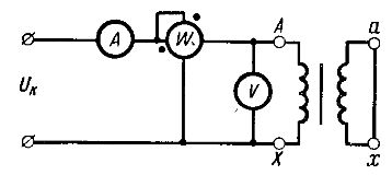
Rice. 3. Diagram of transformer short circuit experiment
Based on the measurement data, the following parameters of the transformer are determined.
Short circuit voltage
![]()
where UK is the voltage measured by a voltmeter at I1, = I1nom. In short circuit mode UK is very small, so no-load losses are hundreds of times less than with rated voltage. Thus, we can assume that Ppo = 0 and the power measured by a wattmeter is the power loss Ppk caused by the active resistance of the transformer windings.
At current I1, = I1nom we get rated power losses for heating the windings Rpk.nom, which are called electrical losses or short circuit losses.
From the voltage equation for the transformer, as well as from the equivalent circuit (see Fig. 1), we obtain
![]()
where ZK is the transformer impedance.
As is known, in load mode the secondary winding of the transformer is connected to the resistance of the receivers. A current proportional to the load of the transformer is established in the secondary circuit. When eating large number receivers, there are often cases when the insulation of the connecting wires is broken. If the wires supplying the receivers come into contact in places where the insulation is damaged, a mode called a short circuit (short circuit) of the circuit section will occur. If the connecting wires coming from the winding are closed somewhere at points a and b, located before the energy receiver (Figure 1), then a short circuit will occur in the secondary winding of the transformer. In this mode, the secondary winding will be short-circuited. At the same time, it will continue to receive energy from the primary winding and give it back to secondary circuit, which now consists only of the winding and part of the connecting wires. 1 - primary winding; 2 - secondary winding; 3 - magnetic circuit Figure 1 - Short circuit on the terminals of the secondary winding of the transformer At first glance, it seems that in the event of a short circuit, the transformer must inevitably collapse, since the resistance r 2 of the winding and connecting wires is tens of times less than the resistance r of the receiver. If we assume that the load resistance r is at least 100 times greater than r 2, then the short circuit current I 2k should be 100 times greater than the current I 2 at normal operation transformer. Because primary current also increases 100 times (I 1 ω 1 = I 2 ω 2), losses in the transformer windings will increase sharply, namely 100 2 times (I 2 r), i.e. 10,000 times. Under these conditions, the temperature of the windings will reach 500-600 ° C in 1-2 s and they will quickly burn out. In addition, when a transformer operates, there are always mechanical forces between the windings that tend to move the winding apart in the radial and axial directions. These forces are proportional to the product of currents I 1 I 2 in the windings, and if during a short circuit each of the currents I 1 and I 2 increases, for example, 100 times, then the forces will increase 10,000 times. Their size would reach hundreds of tons and the windings of the transformer would instantly collapse. However, in practice this does not happen. Transformers usually withstand short circuits for very short periods of time until the protection disconnects them from the network. During a short circuit, the effect of some additional resistance sharply manifests itself, limiting the short circuit current in the windings. This resistance is associated with magnetic leakage fluxes Ф Р1 and Ф Р2, which branch off from the main flux Ф 0 and each close around part of the turns of “their” winding 1 or 2 (Figure 2). 1 - primary winding; 2 - secondary winding; 3 - common axis of the windings and transformer rod; 4 - magnetic circuit; 5 - main scattering channel
Figure 2 - Leakage fluxes and concentric arrangement of transformer windings It is very difficult to directly measure the amount of scattering: the paths along which these flows can be closed are too diverse. Therefore, in practice, leakage is assessed by the effect it has on the voltage and currents in the windings. It is obvious that leakage fluxes increase with increasing current flowing in the windings. It is also obvious that during normal operation of the transformer, the leakage flux constitutes a relatively small fraction of the main flux Ф 0 . Indeed, the leakage flux is coupled only to part of the turns, the main flux is connected to all the turns. In addition, the leakage flux is forced to pass most of the way through air, the magnetic permeability of which is taken as unity, i.e., it is hundreds of times less than the magnetic permeability of steel, through which the flow F 0 is closed. All this is true for both normal operation and short-circuit mode of the transformer. However, since the leakage fluxes are determined by the currents in the windings, and in short-circuit mode the currents increase hundreds of times, the fluxes F p also increase by the same amount; at the same time, they significantly exceed the flow Ф 0. Leakage flows induce self-induction emfs E p1 and E p2 in the windings, directed against the current. Reaction, for example, emf E p2 can be considered some additional resistance in the circuit of the secondary winding when it is short circuited. This resistance is called reactive. For the secondary winding, the equation E 2 = U 2 + I 2 r 2 + (-E p 2) is valid. In short circuit mode, U 2 = 0 and the equation is transformed as follows: E 2 = I 2K r 2K + (-E p2K), or E 2 = I 2K r 2K + I 2K x 2K, where the subscript “k” refers to the resistances and currents in short circuit mode; I 2 K x 2 K - inductive voltage drop in short circuit mode, equal to the value E p 2 K; x 2 K is the reactance of the secondary winding. Experience shows that, depending on the power of the transformer, the resistance x 2 is 5-10 times greater than r 2. Therefore, in reality, the current I 2 K will not be 100, but only 10-20 times greater than the current I 2 during normal operation of the transformer (we neglect the active resistance due to its small value). Consequently, in reality, losses in the windings will increase not by 10,000, but only by 100-400 times; the temperature of the windings during a short circuit (several seconds) will barely reach 150-200 ° C and no serious damage will occur in the transformer during this short time. So, thanks to dissipation, the transformer is able to protect itself from short circuit currents. All the phenomena considered occur during a short circuit at the terminals (inputs) of the secondary winding (see points a and b in Figure 1). This is emergency operation for most power transformers and it, of course, does not occur every day or even every year. During its operation (15-20 years), the transformer may have only a few such severe short circuits. However, it must be designed and manufactured so that they do not destroy it and cause an accident. It is necessary to clearly imagine the phenomena occurring in a transformer during a short circuit, and consciously assemble the most critical components of its design. In this regard, one of the the most important characteristics transformer - short circuit voltage.
1 - primary winding; 2 - secondary winding; 3 - common axis of the windings and transformer rod; 4 - magnetic circuit; 5 - main scattering channel
Figure 2 - Leakage fluxes and concentric arrangement of transformer windings It is very difficult to directly measure the amount of scattering: the paths along which these flows can be closed are too diverse. Therefore, in practice, leakage is assessed by the effect it has on the voltage and currents in the windings. It is obvious that leakage fluxes increase with increasing current flowing in the windings. It is also obvious that during normal operation of the transformer, the leakage flux constitutes a relatively small fraction of the main flux Ф 0 . Indeed, the leakage flux is coupled only to part of the turns, the main flux is connected to all the turns. In addition, the leakage flux is forced to pass most of the way through air, the magnetic permeability of which is taken as unity, i.e., it is hundreds of times less than the magnetic permeability of steel, through which the flow F 0 is closed. All this is true for both normal operation and short-circuit mode of the transformer. However, since the leakage fluxes are determined by the currents in the windings, and in short-circuit mode the currents increase hundreds of times, the fluxes F p also increase by the same amount; at the same time, they significantly exceed the flow Ф 0. Leakage flows induce self-induction emfs E p1 and E p2 in the windings, directed against the current. Reaction, for example, emf E p2 can be considered some additional resistance in the circuit of the secondary winding when it is short circuited. This resistance is called reactive. For the secondary winding, the equation E 2 = U 2 + I 2 r 2 + (-E p 2) is valid. In short circuit mode, U 2 = 0 and the equation is transformed as follows: E 2 = I 2K r 2K + (-E p2K), or E 2 = I 2K r 2K + I 2K x 2K, where the subscript “k” refers to the resistances and currents in short circuit mode; I 2 K x 2 K - inductive voltage drop in short circuit mode, equal to the value E p 2 K; x 2 K is the reactance of the secondary winding. Experience shows that, depending on the power of the transformer, the resistance x 2 is 5-10 times greater than r 2. Therefore, in reality, the current I 2 K will not be 100, but only 10-20 times greater than the current I 2 during normal operation of the transformer (we neglect the active resistance due to its small value). Consequently, in reality, losses in the windings will increase not by 10,000, but only by 100-400 times; the temperature of the windings during a short circuit (several seconds) will barely reach 150-200 ° C and no serious damage will occur in the transformer during this short time. So, thanks to dissipation, the transformer is able to protect itself from short circuit currents. All the phenomena considered occur during a short circuit at the terminals (inputs) of the secondary winding (see points a and b in Figure 1). This is emergency operation for most power transformers and it, of course, does not occur every day or even every year. During its operation (15-20 years), the transformer may have only a few such severe short circuits. However, it must be designed and manufactured so that they do not destroy it and cause an accident. It is necessary to clearly imagine the phenomena occurring in a transformer during a short circuit, and consciously assemble the most critical components of its design. In this regard, one of the the most important characteristics transformer - short circuit voltage. EXPERIENCE OF SHORT CIRCUIT TRANSFORMER
A distinction must be made between a short circuit under operational conditions and a short circuit experience.
Transformer short circuit Its mode is called when the secondary winding of the transformer is short-circuited. In operating conditions, a short circuit is an emergency mode in which a large amount of heat is released inside the transformer, which can destroy it.
Short circuit experience performed at a greatly reduced primary voltage to a small value (approximately 5-10% of the rated primary voltage). Its value is chosen so that the current I 1 in the primary winding is equal to the rated value, despite the short circuit of the secondary winding. Using a set of measuring instruments (Fig. 103), the voltage U 1k, current I 1 k and power P 1 k are determined through experience .
Current I 2 at nominal value I 1 will also have a nominal value. Eds E 2 in this experiment will only cover the internal voltage drop, i.e. E 2 K = I 2 z 2 , and at rated load
2 = 2 + 2
therefore E 2 k is only a few percent of E 2 . Low emf E 2 corresponds to a small main magnetic flux. Energy losses in the magnetic circuit are proportional to the square of the magnetic flux, so during a short circuit experiment they are insignificant. But in both windings in this experiment, the currents have rated values, so the energy losses in the windings are the same as at the rated load. Consequently, the power P 1k received by the transformer from the network during a short circuit is spent on energy losses in the wires of the windings:
P 1K =I 2 1 r 1 +I 2 2 r 2 .
At the same time, based on the short circuit voltage, the voltage drop in the transformer at rated load is determined (in % of the primary voltage). For these reasons, the short-circuit voltage (with a short-circuited winding low voltage) is always indicated on the transformer panel.
Short circuit mode
As is known, in load mode the secondary winding of the transformer is connected to the resistance of the receivers. A current proportional to the load of the transformer is established in the secondary circuit. When powering a large number of receivers, there are often cases when the insulation of the connecting wires is broken. If the wires supplying the receivers come into contact in places where the insulation is damaged, a mode called a short circuit (short circuit) of the circuit section will occur. If the connecting wires coming from the winding are closed somewhere at points a and b, located before the energy receiver (Figure 1), then a short circuit will occur in the secondary winding of the transformer. In this mode, the secondary winding will be short-circuited. At the same time, it will continue to receive energy from the primary winding and transfer it to the secondary circuit, which now consists only of the winding and part of the connecting wires.  1 - primary winding; 2 - secondary winding; 3 - magnetic circuit Figure 1 - Short circuit on the terminals of the secondary winding of the transformer At first glance, it seems that in the event of a short circuit, the transformer must inevitably collapse, since the resistance r 2 of the winding and connecting wires is tens of times less than the resistance r of the receiver. If we assume that the load resistance r is at least 100 times greater than r 2, then the short circuit current I 2k should be 100 times greater than the current I 2 during normal operation of the transformer. Since the primary current also increases by 100 times (I 1 ω 1 = I 2 ω 2), the losses in the transformer windings will increase sharply, namely 100 2 times (I 2 r), i.e. 10,000 times. Under these conditions, the temperature of the windings will reach 500-600 ° C in 1-2 s and they will quickly burn out. In addition, when a transformer operates, there are always mechanical forces between the windings that tend to move the winding apart in the radial and axial directions. These forces are proportional to the product of currents I 1 I 2 in the windings, and if during a short circuit each of the currents I 1 and I 2 increases, for example, 100 times, then the forces will increase 10,000 times. Their size would reach hundreds of tons and the windings of the transformer would instantly collapse. However, in practice this does not happen. Transformers usually withstand short circuits for very short periods of time until the protection disconnects them from the network. During a short circuit, the effect of some additional resistance sharply manifests itself, limiting the short circuit current in the windings. This resistance is associated with magnetic leakage fluxes Ф Р1 and Ф Р2, which branch off from the main flux Ф 0 and each close around part of the turns of “their” winding 1 or 2 (Figure 2).
  1 - primary winding; 2 - secondary winding; 3 - common axis of the windings and transformer rod; 4 - magnetic circuit; 5 - main scattering channel Figure 2 - Leakage fluxes and concentric arrangement of transformer windings It is very difficult to directly measure the amount of scattering: the paths along which these flows can be closed are too diverse. Therefore, in practice, leakage is assessed by the effect it has on the voltage and currents in the windings. It is obvious that leakage fluxes increase with increasing current flowing in the windings. It is also obvious that during normal operation of the transformer, the leakage flux constitutes a relatively small fraction of the main flux Ф 0 . Indeed, the leakage flux is coupled only to part of the turns, the main flux is connected to all the turns. In addition, the leakage flux is forced to pass most of the way through air, the magnetic permeability of which is taken as unity, i.e., it is hundreds of times less than the magnetic permeability of steel, through which the flow F 0 is closed. All this is true for both normal operation and short-circuit mode of the transformer. However, since the leakage fluxes are determined by the currents in the windings, and in short-circuit mode the currents increase hundreds of times, the fluxes F p also increase by the same amount; at the same time, they significantly exceed the flow Ф 0. Leakage flows induce self-induction emfs E p1 and E p2 in the windings, directed against the current. Reaction, for example, emf E p2 can be considered some additional resistance in the circuit of the secondary winding when it is short circuited. This resistance is called reactive. For the secondary winding, the equation E 2 = U 2 + I 2 r 2 + (-E p2) is valid. In short circuit mode, U 2 = 0 and the equation is transformed as follows: E 2 = I 2K r 2K + (-E p2K), or E 2 = I 2K r 2K + I 2K x 2K, where the subscript “k” refers to the resistances and currents in short circuit mode; I 2K x 2K - inductive voltage drop in short circuit mode, equal to the value E p2K; x 2K is the reactance of the secondary winding. Experience shows that, depending on the power of the transformer, the resistance x 2 is 5-10 times greater than r 2. Therefore, in reality, the current I 2K will not be 100, but only 10-20 times greater than the current I 2 during normal operation of the transformer (we neglect the active resistance due to its small value). Consequently, in reality, losses in the windings will increase not by 10,000, but only by 100-400 times; the temperature of the windings during a short circuit (several seconds) will barely reach 150-200 ° C and no serious damage will occur in the transformer during this short time. So, thanks to dissipation, the transformer is able to protect itself from short circuit currents. All the phenomena considered occur during a short circuit at the terminals (inputs) of the secondary winding (see points a and b in Figure 1). This is an emergency mode of operation for most power transformers and, of course, it does not occur every day or even every year. During its operation (15-20 years), the transformer may have only a few such severe short circuits. However, it must be designed and manufactured so that they do not destroy it and cause an accident. It is necessary to clearly imagine the phenomena occurring in a transformer during a short circuit, and consciously assemble the most critical components of its design. In this regard, one of the most important characteristics of the transformer, the short-circuit voltage, plays a very significant role.
Determination of transformer parameters
Quite by accident, the reader may fall into the hands of an old output transformer, which, judging by appearance, should have good characteristics, but there is absolutely no information about what is hidden inside it. Fortunately, it is possible to easily identify the parameters of an old output transformer with only a digital universal voltmeter, since their design always follows strictly defined rules.
Before starting the test, you need to sketch out a diagram of all the external connections and jumpers on the transformer, and then remove them. (Using a digital camera for this purpose has proven to be very fruitful.) Of course, the primary winding must have a midpoint tap to allow the transformer to be used in a push-pull circuit, and there may be additional taps on this winding to provide ultra-linear operation. As a rule, the DC winding resistance, measured with an ohmmeter between the extreme points of the winding, will be the maximum resistance value among all the values obtained and can range from 100 to 300 ohms. If a winding with a similar resistance value is detected, then, in almost all cases, we can assume that the transformer terminals A 1 and A 2 corresponding to the extreme points of the primary winding have been identified.
For high-quality transformers, the primary winding is wound symmetrically, that is, the resistance between the extreme terminals A 1 and A 2 and the midpoint of the high-voltage winding is always equal, so the next step is to determine the terminal for which the resistance between it and terminals A 1 and A 2 would be equal half the resistance between the extreme points of the primary winding. However, cheaper models of transformers may not be made as carefully, so the resistance between the two halves of the winding may not be exactly equal.
Since for the manufacture of the primary winding of the transformer, without any exceptions, a wire of the same cross-section is used, the tap, which is located on a turn constituting 20% of the total number of turns between the central high-voltage tap and terminal A 1 or A 2, (configuration for taking the full power of the amplifier) , will also have a resistance of 20% of the resistance value between the outer terminal A 1 or A 2 and the central tap of the primary winding. If the transformer was intended for a higher quality amplifier, then the most likely location of this tap would be a turn corresponding to 47% of the resistance between these same points (the power amplifier configuration that provides minimal distortion).
The secondary winding will most likely also have an even number of leads, or will have one tap. It is worth remembering that in the heyday of vacuum tubes, speaker impedances were either 15 ohms (premium loudspeakers) or 4 ohms, so the output transformers were optimized for these impedances.
The most common option is to use two identical sections, using the windings in series for 15 ohm speaker impedances, or in parallel for 4 ohm impedances (actually 3.75 ohms). If, after the primary winding of the transformer has been determined, two windings are found with DC resistances of about 0.7 ohms each, then most likely there is a standard transformer sample.
In high quality transformers, the above idea is further developed when the secondary winding is represented by four identical sections. Wired in series they are used to terminate a 15 ohm load, however when all connected in parallel they will terminate a 1 ohm load. This is not due to the fact that 1-ohm speakers were available (the era of poor-quality crossovers had not yet arrived), but because a greater degree of sectionalization of the windings allowed for a higher quality transformer. Therefore, you should look for four windings with approximately the same resistance in terms of DC and equal in value to approximately 0.3 Ohm. It must also be borne in mind that in addition to the fact that the contact resistance of the probe can make up a very significant proportion when making measurements of very small resistances (which makes it imperative to have not only a clean but also a reliable contact), but also that the usual 41/ A 2-digit digital voltmeter does not provide sufficient accuracy when measuring such small resistance values, so you often have to make guesses and assumptions.
If, after identifying the primary winding, it is determined that all the remaining windings are connected together, then there is a secondary winding with taps, the highest value of resistance of which is measured between the 0 Ohm and (say) 16 Ohm terminals. Assuming that there is no winding tap matching the 8 ohm resistance, then the lowest DC resistance from any of these leads will be the 4 ohm tap, and the point with 0 ohm resistance will be closest to the 4 ohm tap (usually in the secondary windings with interturn taps, they tend to use a thicker wire for the 4 Ohm tap). If the presence of an 8 ohm tap is to be expected, then the taps should be identified using the measurement method at alternating current, which will be described below.
If the purpose of some windings cannot be determined, then most likely they are intended for feedback, possibly acting on the cathodes of individual output lamps, or for organizing interstage feedback.
In any case, their more accurate identification can be carried out later, since the next step is to determine the transformation ratio, and then, based on the results obtained, determine the impedance of the primary winding of the transformer.
Attention. Although the following measurements should not pose a safety hazard to the output transformer if carried out accurately, there may be voltages that pose a danger to human life. Therefore, if there are any kind If you have doubts about the professional experience required to perform the measurements described below, you should immediately abandon attempts to perform them.
The output transformers of tube circuits are designed to reduce the voltage from several hundred volts to tens of volts in the frequency range from 20 Hz to 20 kHz, so the application of mains voltage to the terminals of the primary winding A 1 and A 2 does not pose any threat to the transformer. Provided that terminals A 1 and A 2 have been identified correctly, you should apply mains voltage directly to terminals A 1 and A 2 and measure the voltage on the secondary winding to determine the transformation ratio (or the ratio of the number of turns of the primary and secondary windings). Strictly speaking, for safety reasons, it is recommended to supply not the mains voltage, but a reduced voltage from the LATR.
Transformer testing should be performed in the following order:
Install a fuse in the power cord with the lowest fuse current available, for example, a 3 A fuse will be sufficient, but using a 1 A fuse will be preferable;
Connect three short flexible wires to the power plug (preferably with a grounding pin). For obvious reasons they are called "suicide wires" and should therefore be kept separate and locked when not in use;
Solder a tinned lug to the end of the wire labeled "ground" and screw the lug to the metal chassis of the transformer using special serrated washers to ensure very good electrical contact;
Solder the phase wire to terminal A 1, and the neutral (zero) wire to terminal A 2;
Make sure that the position of all connecting jumpers on the secondary skein is sketched, after which they are all removed;
Set the measurement type of the digital voltmeter to “alternating voltage” and connect it to the terminals of the secondary winding;
After making sure that the instrument scale is within sight, plug the power plug into the socket. If measurement results do not immediately appear on the device, unplug the plug from the socket. If the device detects the presence of
voltage in the secondary winding, the value of which can be determined, wait until the device readings stabilize, write down the result, turn off the mains power and unplug the plug from the power outlet;
Check the value of the mains voltage; to do this, connect a digital voltmeter to terminals A 1 and A 2 of the transformer and turn on the mains voltage again. Write down the device readings.
After this, you can determine the transformation coefficient "N" using the following simple relationship between voltages:
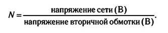
At first glance, this procedure does not seem very significant, but it should be remembered that impedances are proportional to the square of the transformation ratio, N 2, therefore, knowing the value N it is possible to determine the impedance of the primary winding, since the impedance of the secondary is already known. Of all the numerous wires, the transformer has five wires that turned out to be electrically connected to each other (the results were obtained when electrical resistance measurements were taken using digital tester). The maximum resistance value between two wires is 236 ohms, therefore, the terminals of these wires can be labeled as A 1 and A 2. After one probe of the digital tester remained connected to pin A 1, a second wire was detected with a resistance of 110 ohms. The resulting value is close enough to the resistance value of 118 ohms that this point could be the output from the center point of the transformer primary winding. Therefore, this winding can be identified as a high-voltage winding of a transformer. After this, you should move one of the probes of the digital tester to the middle tap of the high-voltage winding and measure the resistance relative to the two remaining leads. The resistance value for one terminal was 29 Ohms, and for the second it was 32 Ohms. Given that (29 ohms: 110 ohms) = 0.26, and (32 ohms: 118 ohms) = 0.27, it is safe to assume that these pins are used as ultra-linear taps for maximum power (i.e. approximately 20% of the winding). One of the terminals, for which the resistance relative to terminal A has a lower value, represents a tap to the grid 2 lamps V 1 , g 2(V1) and the second tap - to the grid of 2 lamps V 2 , g 2(V2) (Fig. 5.23).
The secondary winding has only two sections, so they are most likely intended to carry a 4 ohm load. This assumption is then confirmed by measurements of the resistance of the windings of the sections, for the first of them it was 0.6 Ohm, and for the second 0.8 Ohm, which coincides with typical values for windings designed to match 4 Ohm loads.

Rice. 5.23 Identification of transformer windings with unknown parameters
When connecting the transformer to the network, an alternating mains voltage of 252 V was recorded, and the voltage on the secondary windings was 5.60 V. Substituting the obtained values into the formula for calculating the transformation ratio, we obtain:
The impedances of the windings change proportionally N 2, so the ratio of the primary impedance to the secondary impedance is 45 2 = 2025. Since the secondary voltage was measured at a 4 ohm section, the primary impedance should be (2025 x 4 ohms) = 8100 ohms. This result is quite acceptable, since measurements using a mains voltage of 252 V and a frequency of 50 Hz could shift the operating point closer to the saturation region, which led to errors in determining the parameters. Therefore, the resulting value can be rounded to 8 kOhm.
Next, it is necessary to determine the beginning and end of the windings of each section of the secondary winding of the transformer. This is done by connecting only one wire between the first and second sections, thus turning the windings of the sections in series. After applying voltage to the primary winding, we get twice the voltage on the secondary winding, compared to the individual voltage on each. That is, the voltages of the two sections complement each other and, therefore, the end of the winding of the first section turned out to be connected to the beginning of the winding of the second, so we can designate the output of the section where the connecting wire ends as “+”, and the other end as “-”. However, if there is no voltage on the secondary winding, this will mean that the windings in the two sections are connected opposite each other, so both terminals can be designated either as “+” or “-”.
After all sections with identical characteristics have been identified, and the starting points of the windings have been determined for them, the voltages on all remaining windings can be measured, and the transformation ratios can be determined for them, either relative to the primary winding or relative to the secondary, depending on which the method will be more convenient. From this point on, it is most convenient to use a circuit with short notes, for example, obtaining a twofold increase in the voltage of the secondary winding is very significant, since this fact can mean either the presence of a section with a tap from the midpoint, or taps of 4 Ohms and 16 Ohms.
The main reasons for the failure of transformers in the audio frequency path
Transformers are among the electronic components with the most long term service reaching 40 years or more. However, sometimes they can fail. The transformer windings are made of wire, which can fail if too high currents flow through it, and the wire insulation can be pierced if the voltages applied to the windings exceed permissible values.
The most common case in which output transformers fail is when it is forced to operate the amplifier in overload mode. This can happen in a push-pull amplifier when one output tube is completely disabled (for example, failed) and the second is operating with obvious overload. The leakage inductance of that half of the transformer, which should pass the current of the switched-off lamp, tends to maintain the current of this half of the winding unchanged, which entails the appearance of significant overvoltages in the primary winding (primarily due to the self-induction emf), leading to breakdown of the interturn insulation. The process of changing the voltage on the inductive winding over time is characterized by the following differential equation:

Since when the current breaks, its derivative tends to infinity di/dt ≈ ∞, the resulting self-induction EMF develops a voltage on the half-winding in the circuit of the failed lamp, significantly exceeding the value of the high-voltage power source, which can easily break through the interturn insulation.
Also, insulation breakdown can be caused by improper operating conditions of the equipment. So. for example, if moisture penetrates into the transformer, the insulation (which is most often used as special paper) becomes more conductive, which significantly increases the likelihood of its breakdown.
There is also a risk of failure of the output transformer if the amplifier is driven by loudspeakers whose impedance is significantly lower than required. In this case, at high volume levels, the currents flowing through the transformer windings may be significantly exceeded.
Another specific problem in some cases arises in not very high-quality amplifiers, for example those that were at one time widely used for electric guitars. Due to the fact that the rate of rise of current during overload is very high, and the quality of the output transformer used in electric guitar amplifiers is usually not very good, high values of leakage inductance can lead to such high values voltage (self-induction emf) on the windings, which does not exclude the occurrence of an external electric arc. Moreover, the transformer itself could be designed in such a way as to safely withstand such an accidental overvoltage. The voltage required to initiate an electric arc depends to some extent on the degree of contamination of the path along which it develops, so contamination (especially conductive) reduces this arc voltage. This is why the carbon footprints left over from previous arcing processes undoubtedly lead to a reduction in the voltage required for a new arcing process to occur.
All transformers operate in two main modes: under load and at Idling. However, another operating mode is known, in which the mechanical forces and leakage flux in the windings sharply increase. This mode is called transformer short circuit. This situation occurs when the primary winding receives power and the secondary winding closes at its inputs. During a short circuit, reactance occurs, while current continues to flow into the secondary winding from the primary.
Then the current is given to the consumer, which is the secondary winding. Thus, the process of short circuiting the transformer occurs.
The essence of a short circuit
In a closed section, resistance arises, the value of which is much less than the load resistance. There is a sharp increase in primary and secondary currents, which can instantly burn the windings and completely destroy the transformer. However, this does not happen and the protection manages to disconnect it from the network. This is due to the fact that the increased dissipation and fields of the transformer significantly reduce the impact of short-circuit currents, and also protect the winding from electrodynamic and thermal loads. Therefore, even if there are losses in the windings, they simply do not have time to have their negative impact.
Short circuit warning
During normal operation of the transformer, the value of electrodynamic forces is minimal. During this time, currents and forces increase tenfold, creating a serious danger. As a result, the windings can be deformed, their stability is lost, the coils bend, and the gaskets are crushed under the influence of axial forces.
In order to reduce electrodynamic forces, the windings are axially pressed during assembly. This operation is performed repeatedly: first, when the windings are mounted and the upper beams are installed, and then, after drying the active part. The second operation is of particular importance for reducing forces, since in case of poor-quality pressing, under the action of a closure, the coil may shift or be destroyed. A serious danger is posed by the coincidence of the coil's own resonance with the frequency present in the electrodynamic force. Resonance can cause forces that are not at all dangerous during normal operation.
To improve the quality of the transformer, during assembly it is necessary to immediately eliminate possible insulation shrinkage, level all heights, and ensure high-quality pressing. Subject to compliance with the necessary technological processes, a short circuit of the transformer may well do without serious consequences.