Reader Anton emailed me with a question regarding the correct assembly and selection of circuit breakers for an apartment panel. Despite the fact that I already have at least 3 articles devoted to this issue, I decided to delve into this topic once again. I invite my readers to speak in the comments on this topical topic.
To begin with, here is a list of my articles, which I strongly recommend you read. They outline necessary points that may not be discussed in this article.
- depending on the power and load current,
- and circuit breaker,
- Protection and loads.
Here's the actual question:
Hello!
I have carefully studied your blog.
Perhaps you can advise me on circuit breakers?
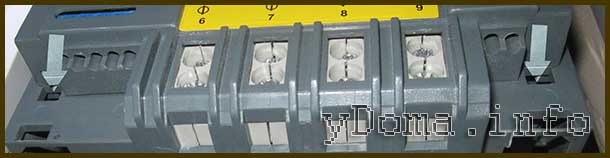
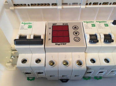
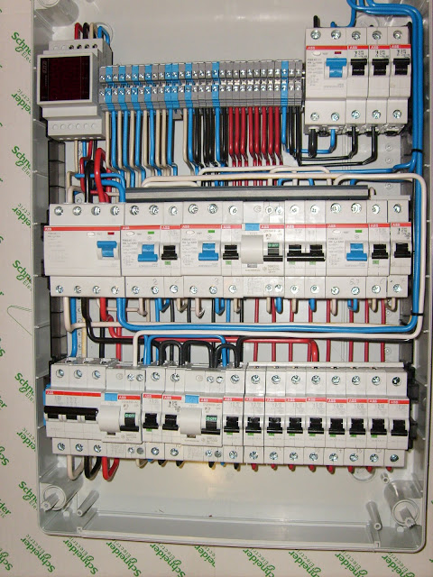
For renovations in my apartment, my electricians purchased and installed Schneider Electric household circuit breakers (see photo).
As a result of a deep study of this issue on the Internet and in life, I did not find a consensus among electricians, nor in regulatory documents(PEU, GOST). For example, some electricians standardly recommend installing a 25A circuit breaker on 2.5 mm2, while another part seems to be justified, referring to the time-current characteristics of the circuit breakers and the maximum permissible current for the cable, and says that this is not possible and only 16A is needed (see pictures of “circuit breakers” ). Similarly with other sections (1.5, 4, 6 mm2). And I did not find a clear legalized solution.
Alexander, let me clarify - the cables are laid along the ceiling, but they are then lowered along the walls in the plaster. And on the ceiling, on top of the cables, I also have sound insulation made of non-flammable glass wool.
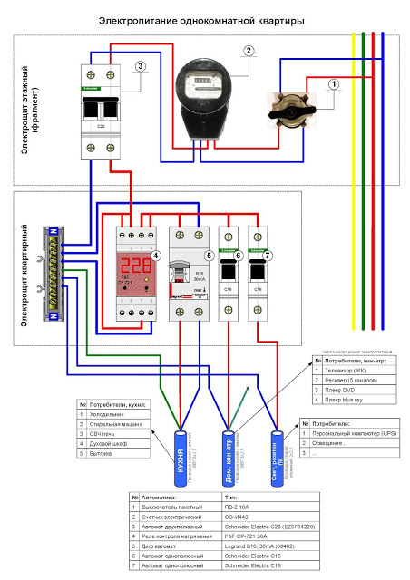
I ask you to act as an arbitrator and look at the linear diagram of the electrical panel (see below) and express your opinion on the admissibility of the selected machines for the given cable cross-sections and power of the devices.
I am posting photos and diagrams that Anton sent:
As usual on my blog, all the pictures can be zoomed in and examined in detail.
Photo 1. Scheme of the access panel. These are the original plans for apartment panels. Pay attention to the machine denominations.

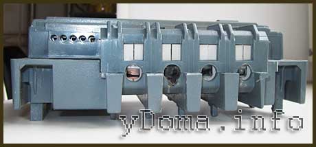
Photo 2. New shield, general plan
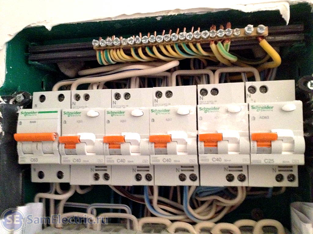
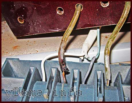
Photo 3. Top row of the shield. The rated current of differential automatic machines is 40A in front of the 2.5 mm2 wires. Not at any gate(
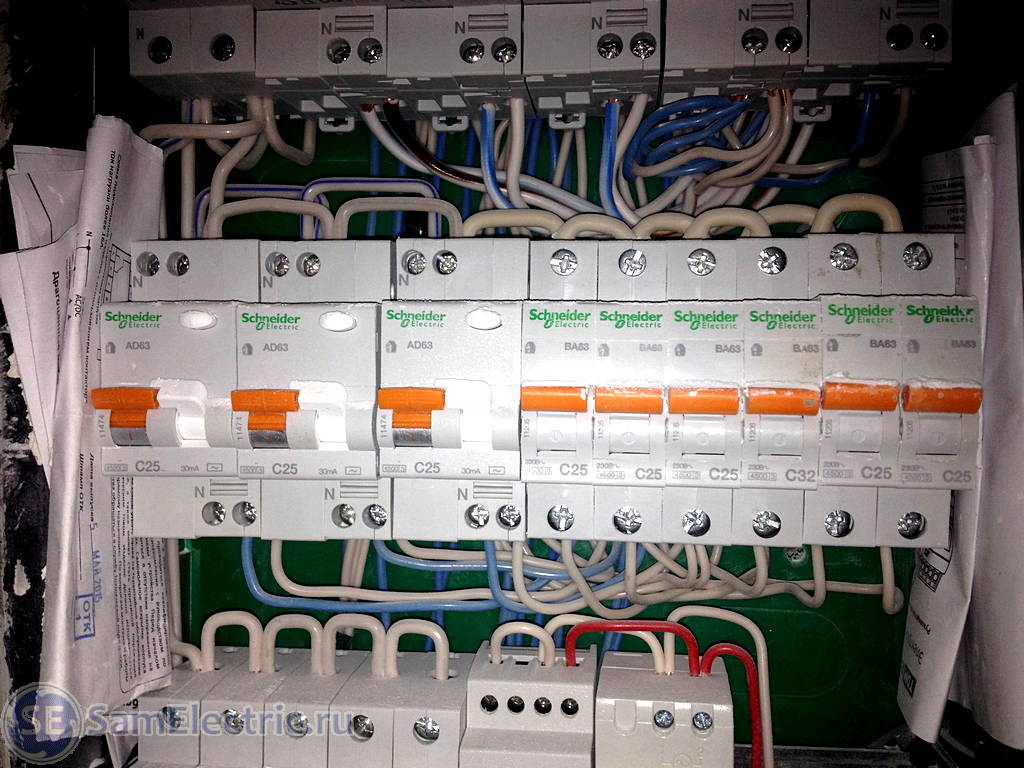
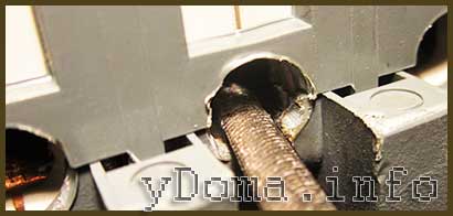
Photo 4. Apartment shield. Middle row.
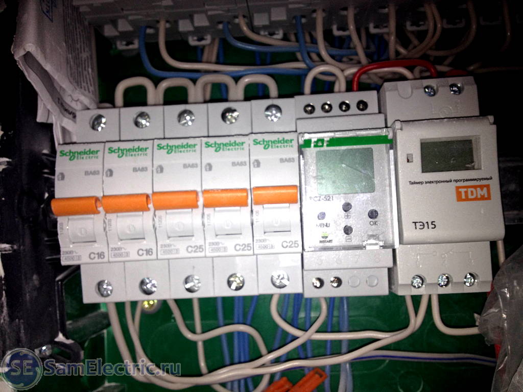
Photo 5. Apartment shield. Bottom row.
Photo 6. Linear diagram of an apartment electrical panel from electricians
Photo 7. Installed machines. Groups and their characteristics
My reader expressed complaints to the electricians who installed this electrical panel regarding the overestimated ratings of the machines. I agree with him, and am more inclined towards the following denominations:
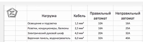
Photo 8. Safety circuit breakers. Right and wrong
Modern safety requirements are becoming more stringent, and this applies not only to electrical equipment, but to all areas of human activity. Take, for example, transport.

Photo 9. Automatic machines for different sections
As you can see, the rating of the machine greatly depends on the installation method.
Now I will express my opinion on this issue.
How to choose the right machine guns for the dashboard?
The following factors influence the choice of circuit breakers.
1.
Load power (consumer)
2.
Cable cross-section
3.
Cable laying method
4.
Temperature in the shield (package density)
5.
6.
Acceptable wear and service life, monetary costs for reliability.
More details point by point.
1. Load power
This is the primary parameter from which further calculations are made.
Let’s take group 5 from our example. This is bathroom 1, design power 3 kW. Current consumption = 3000 W/220V= 13.6A. It is worth saying that this current will be present if everything in the bathroom is constantly on full power. This almost never happens, but we take exactly this extreme case.
Moreover, the Law states:
1.3.3 . For intermittent and short-term operating modes of electrical receivers (with a total cycle duration of up to 10 minutes and a working period of no more than 4 minutes), the current reduced to the long-term mode should be taken as the calculated current for checking the cross-section of heating conductors. Wherein:
1) for copper conductors with a cross-section of up to 6 mm 2, and for aluminum conductors up to 10 mm 2, the current is taken as for installations with long-term operation;
2) for copper conductors with a cross-section of more than 6 mm 2, and for aluminum conductors with a cross-section of more than 10 mm 2, the current is determined by multiplying the permissible long-term current by the coefficient where T p.v is the duration of the operating period expressed in relative units (on duration in relation to the cycle duration).
1.3.4 . For short-term operating mode with a switching duration of no more than 4 minutes and breaks between switching on sufficient to cool the conductors to temperature environment, the highest permissible currents should be determined according to the standards of intermittent duty (see 1.3.3.). When the duration of switching on is more than 4 minutes, as well as during breaks of insufficient duration between switching on, the maximum permissible currents should be determined as for installations with a long operating mode.
Therefore, when calculating the power for a group, we ignore all the talk like “we never turn everything on at once,” and take the maximum possible current. And this is the sum of the powers of all devices connected through this cable.
Apparently, in the case of Anton, the electricians took a 40A automatic machine for group 3 based on these considerations... Although no, this is inexplicable to me.
2. Selection of cable cross-section
We select the cross section based on the PUE tables (Electrician's Bible). Namely, table 1.3.4:
Permissible continuous current for wires and cords with rubber and polyvinyl chloride insulation with copper conductors.
Conductor cross-section, mm 2 | Current, A, for wires laid |
|||||
in one pipe |
||||||
two single core | three single core | four single core | one two core | one three core |
||
In our case (one phase and zero), a cable with two cores is used, the cable is laid in a thermally insulated wall, so we need to take the column “two single-core in one pipe.”
Tired of it? Maybe this will be interesting:
Continuation of the article:Since in residential premises for hidden wiring It is forbidden to use a wire with a cross-section of less than 1.5 mm², then choose 1.5 mm², for which the maximum current in this case is 19A. Seems to be OK. Bye.
3. Cable laying method
The way the cable is laid determines how it is cooled during operation. Maximum working temperature cable for different brands and manufacturers are indicated in the range of 60...70 °C, and in case of an accident (short circuit, overload) a short-term temperature of up to 85 °C is allowed.
60...70 °C is when it feels “hot, but your hand is still tolerant.” Manufacturers do not recommend using cables in extreme mode; it is recommended to select an operating current of no more than 80% of the nominal value (utilization factor 0.8). And this is for our case - 19x0.8=15.2A
4. Temperature in the shield and packaging density
This includes the density of the wires, which in some areas run in a bundle, and the density of the installation of circuit breakers in the panel, which stand close together and heat up during operation.
As a result, the operating current of the cables decreases (see the previous paragraph), and the thermal current of the machines also decreases. Lowering the setting of the machines is a safety benefit - the machine will work earlier than in a “cool” environment.
5. Method of connecting wires in junction boxes
Any connection of wires has a transition resistance; the voltage drops across it. This means heating occurs. The circuit breaker protects not only the cable, but also the connections in the distribution board. boxes. And the better quality they are, the less chance that the twist will burn out in the event of a short circuit or overload.
Where it's thin, that's where it breaks. And this is the thinnest place in the electrical wiring must be a circuit breaker.
I believe that all types of connections have the right to life - and, and, and sleeves, and welding, and simple twisting. And their quality depends primarily on the conscience and professionalism of the electrician.
Taking into account the contacts, the maximum current of the electrical system must also be reduced to 0.7 of the maximum. cable current. And this 19x0.7=13.3A
6. Acceptable wear and service life, monetary costs for reliability
The manufacturer usually specifies the service life of a cable with a copper core at 30 years. This average term at average operating rates. I believe that the service life of the cable and all electrical wiring of the apartment can be increased to 50 years by choosing a cable utilization factor of 0.7. That is, we select the cable current for our conditions from the table 1.3.4 , and take 70% from it. For a 1.5 mm² cable, I recommend taking a calculated operating current of 13A.
The following are factors that also affect the reliability and service life of the electrical system:
Sockets. Sockets usually indicate a maximum current of 16A, but for long-term operation it should also be limited to 13 Amps. The service life of the socket is usually less than the life of the cable, and this is primarily affected by the maximum current.
Cable. When heated and cooled, any material loses its qualities. The cable parameters also deteriorate—first of all, the insulation strength. Therefore, it is advisable to exclude large temperature changes. When the cable is used at 70%, it is unlikely to heat up above 35°C, and the differences will be insignificant.
Length of cable. Within the apartment length cable line(from apartment electrical panel to the farthest load) is unlikely to be more than 30m. But if the cable length is more than 30 m, then this is another reason to choose a cable one step thicker.
Manufacturer. Now the cross-sectional area of the core is being underestimated everywhere, this must be taken into account. In addition, the calculations assume that pure copper is used for the core material. However, there are suspicions that impurities are added to the alloy. And it’s unlikely to be gold or silver).
Conclusion on the selection of machines in the dashboard
For our case (bathroom 1, estimated power 3 kW. Current consumption = 3000 W/220V= 13.6A) Based on the above, we will select a cable and a circuit breaker.
For a current of 13.6A, a 1.5 mm² cable can only be used at the expense of safety. Moreover, given the immutable rule
The rated current (setting) of the circuit breaker must be greater than the maximum load current, but less than the permissible cable current,
we see that the machine is needed at 10A, which is not suitable for powering a 3 kW load.
Therefore, we choose a 2.5 mm² cable for this group. According to the table 1.3.4 and with an adjustment of 70%, its maximum current for normal operation will be equal to 27x0.7 = 19A.
Let's check the protection. We choose a 16A machine, which is greater than the maximum load current. Here we need current-time characteristics, which I present once again:
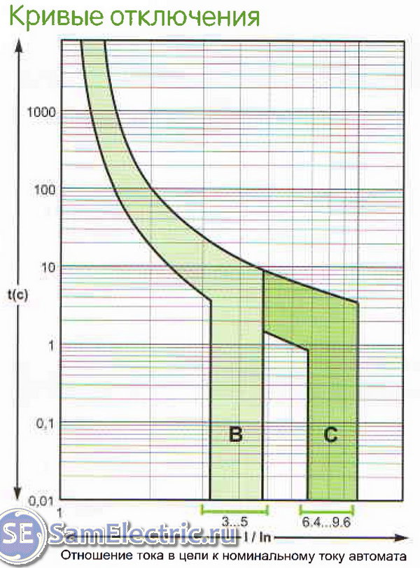
Tripping curves or current-time characteristics
They are also called ampere-second.
A 16A circuit breaker with characteristic C at a current of 19A (1.18 times more than the nominal value) will work without knowing when! If you mentally continue the curve on the graph upward, you can assume that this will happen in 10,000 seconds, which is more than 2 hours! But it is not all that bad. If we take the current from the table, then at 27 A (more than the rating of the machine), the machine will work in 30 to 100 seconds. Depending on your luck.
It turns out that for a 2.5 mm² cable protected by a 16A circuit breaker, there are operating modes when it will heat up for some time. But for a cable this mode will be relatively short-lived. For example, according to the table 1.3.1 PUE, within half an hour it is allowed to increase the current by 20% of the nominal value (although this is for paper-insulated cables).
Expanded comments. I also give Option, in which the ratings are brought to the same level with a slight decrease in reliability and a possible increase in the load on the group.
Gr.1. Everything is fine here, nothing needs to be changed. I hope the connection through the terminals is made securely?
Gr.2. The cable current is 4.0 mm², taking into account the 70% margin, we take 38x0.7 = 26A. It will be perfectly protected by a machine with a rated current of 20A. Since there is no increase in current during startup, it is better to take a machine with characteristic B. Connection is also necessary through the terminals. Option - C25.
Gr.3. The most problematic group. Why did electricians choose such a cable under significant load? Because it is problematic to connect 4.0 mm² residential sockets. To protect the cable, you need a C20 circuit breaker, but this will not allow you to connect the entire planned load. In any case, 42A cannot be passed through a 2.5 mm² cable. Now you need to either distribute the load over time, or pull another line to additional block sockets, or use the line on hob(Gr.2), or line oven(Gr.4). The option is C25, but the cable may be overloaded.
Gr.4. The power is small for such a cable, so the C16 rating is sufficient. An option is C25, especially if part of the current is used for the needs of kitchen outlets.
Gr.5. B16. Option - C16
Gr.6. B16. Option - C16
Gr.7. Warm floor. B16 or even B10. Option - C16
Gr.8. Washing machine. C16. There are no options.
Gr.9. Bedroom. B16. Option - C16
Gr.10. Cabinet. B16. Option - C16
Gr.11. Air conditioner. C16. There are no options.
Gr.12. Fridge. C10. There are no options.
Gr.13. Corner. AT 10 O'CLOCK. Option - C10.
Gr.14. Equipment. AT 10 O'CLOCK. Option - C10, or C16, if it is possible to increase the load, for example, turning on a vacuum cleaner.
Gr.16. Projector. AT 10 O'CLOCK. Option - C10 or C16.
It remains unclear how the lighting is connected (via Gr.12?). It is better to connect it via B10. Option - C10.
I ask all my readers to share their thoughts and experiences in the comments.
Electricity is supplied to the apartment from a panel installed in the entrance of the house through a meter, which serves to record the amount of electricity consumed. The meter is installed at the entrance or in the apartment, and is the property of the apartment owner.
Attention! Before work on replacing or repairing the meter and circuit breakers, to avoid damage electric shock, it is necessary to de-energize the electrical wiring. To do this, turn off the circuit breaker in the distribution panel, which is usually located on landing and check the reliability of its shutdown using the phase indicator.
How to choose an electric meter
Currently, when replacing outdated mechanical electricity meters and when installing new electrical wiring in an apartment, as a rule, electronic two-tariff electricity meters are installed. The ability of the meter to separately take into account the consumed electricity during the day and at night will reduce the cost of paying for electricity, since the night tariff is cheaper.
When choosing an electric meter for an apartment, you need to take into account only two parameters: the maximum load current for which the meter is designed and the accuracy class. The current consumed even in the most saturated apartment with electrical appliances does not exceed 60A. The optimal accuracy class is the second, because the higher the accuracy of the electric meter readings, the more expensive it is.
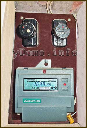
Thus, for installation in any suitable for apartment electronic single-phase two tariff electricity meter any type for a load current of 60 A of the second accuracy class. Budget model is a modern electronic two-tariff single phase electricity meter domestic manufacturer"Mercury 200.02", which is installed in my apartment and has been working reliably for more than one year. Its appearance is shown in the photographs of this article.
How to connect an electric meter
Everyone is familiar with the electric meter, since you have to take its readings every month to calculate the electricity consumed, which is measured in kilowatt-hours (kW×h). Electricity meters are mechanical, electromechanical and electronic. IN Lately Only electronic meters are installed. Regardless design differences meters, they are connected according to the same electrical circuit.
The photograph shows an electrical diagram for connecting an electric meter using the Mercury 200 meter as an example. The phase wire coming from the access panel is always connected to the first left contact of the meter, and the load is connected to the second contact, from which the phase wire comes out. The following contacts, which are interconnected inside the meter, are connected to neutral wire. After connecting the wires to the electric meter, the screw group is closed with a lid and sealed.
Wiring diagram
connections of devices in the electrical panel
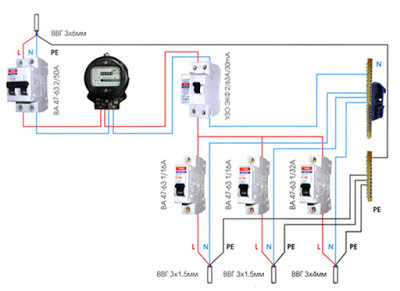
Below is a photograph of the wiring diagram for connecting the meter, circuit breakers and RCDs to each other in electrical panel. The scheme is typical for a small city apartment or country house.
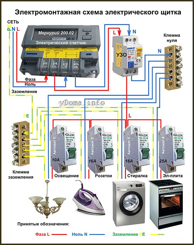
Electricity with circuit breaker, installed in the electrical panel of the entrance, is fed directly to the electric meter and then to the RCD, if used. If there is no RCD, then from the meter the phase wire L goes directly to the circuit breakers, and the zero wire to the terminal strip. The PE grounding wire is connected directly to the grounding bar.
If it is necessary to install an RCD in separate branches of electrical wiring, for example in a bathroom, it can be connected to a wire break anywhere, both before and after the circuit breaker. You can install the RCD directly on the wall before entering the electrical wiring into the bathroom in an additional small electrical box.
My panel was created for the existing electrical wiring and consists of only an electric meter and two circuit breakers. I replaced the connection of wires using a terminal strip and jumpers with strands soldered with solder. PE ground wire in apartment electrical wiring is missing, so it remains unconnected.
How to select and connect a machine
protection of electrical wiring
The circuit breaker is intended solely to protect electrical wiring from destruction. Therefore, it is selected based on the wire cross-section, which in turn is selected based on the result of calculating the maximum current consumption of electrical appliances connected to the electrical wiring after the machine. To protect the electrical appliances themselves, they are equipped with their own protection, usually in the form of a fuse.
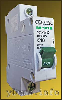
The photo shows a modular circuit breaker type BA101 with shutdown characteristic C, designed for network operation AC voltage 220V and protection current 10A. Basic specifications usually written on the body of the machine.
Principle of operation
automatic switch (automatic)
For the right choice machine let's look at how it works. The machine performs two protection functions at once - against instantaneous current surges exceeding several times the rated current, and slow thermal protection, triggered when the current is slightly exceeded. rated current load for 15-60 minutes.
An instantaneous surge of current can only occur if there is a short circuit in the electrical wiring or electrical appliance connected to it. During a short circuit, the current in the wires can reach 100 A, and if a circuit breaker had not been installed, the entire insulation would have melted first, then the wires themselves. The electrical wiring would be completely unusable.
The thermal protection is made specially slow and this is necessary to eliminate false alarms of the machine. For example, a machine with a nominal value of 25 A is loaded with a current of 15 A. You turned on a vacuum cleaner, which will add another 10 A. But at the moment of starting, any engine consumes a current much higher than the rated one, and when the vacuum cleaner was turned on, its current consumption could momentarily increase to 15 A. As a result on a short time the current flowing through the machine will be 30 A. But due to the inertia of the thermal protection, the machine does not operate.
How to choose a circuit breaker
When choosing a circuit breaker, you should take into account that it intended solely for protecting electrical wiring, not electrical appliances. Installed in electrical appliances individual system protection, ranging from the most primitive, for example, a fuse, to electronic protection with increased speed.
Automatic switches for protecting household electrical wiring according to the standard are available for the following protection currents: 1, 2, 3, 6, 10, 16, 20, 25, 32, 40, 50 and 63 A. Therefore, after the wire cross-section for electrical wiring, using the table you can select the rating of the circuit breaker.
In addition to the protection current, the circuit breaker must be designed for operation in the electrical network alternating current voltage 220 V, frequency 50 Hz, with shutdown characteristic type C(the current value at which the machine will operate is equal to the rated current of the machine, multiplied by 5-10) and class 3(operation time is less than 1/3 of the half-cycle of a sinusoid).
Different sources give different recommendations for choosing circuit breakers. The fact is that the technical characteristics of the machines differ greatly even among copies of the same type. For example, the tripping current during an overload is determined by the shutdown characteristic, which is designated by the letters B, C or D. For household electrical wiring, a machine with characteristic C is recommended, which provides a short circuit protection current within the range, for example, for a 25 A machine, from 125 to 250 A. This means that one copy of the machine will work when a current of 125 A flows through it, and another, of the same type, when a current of 250 A flows through it. If the current value is slightly exceeded, the machine with a protection current of 25 A will work, thanks to a thermal relay, only if a current of 28-36 A flows through it for 0.5 to 1 hour.
The electrical wiring in my apartment is many years old, it is made of copper wire with a core diameter of 1.8 mm and according to the table, you need to install a circuit breaker with a protection current of 10-16 A. The electrical wiring is divided into two circuits. One circuit covers rooms where the current consumption does not exceed 10 A, and the second circuit covers all other rooms with a current consumption of 16 A. Based on these conditions, two circuit breakers with a current of 10 A and 16 A were chosen to replace the automatic plugs.
When choosing a machine, you need to take into account that the actual current of its protection is greater than that indicated in the passport. Therefore, when choosing a circuit breaker according to the table, if the wire cross-section does not fall within standard series, you need to select a machine with a lower protection current. For example, the calculated cross-section of the electrical wiring turned out to be 1.7 mm 2, which turned out to be between the values of 1.5 and 2.0. In this case, you need to choose a machine with a protection current of 10 A.
It is important to note that when choosing a circuit breaker, you should take into account not only the cross-section of the electrical wiring in the apartment, but also the cross-section of the wires coming to the meter. It may well turn out that new wiring the apartment is laid with a wire with a cross-section of 2.5 mm 2, and from the panel in the entrance comes a wire with a cross-section of 1.5 mm 2. In this case, you need to install the machine based on the smallest wire cross-section, or replace the wires coming to the meter from the panel with wires with a larger core cross-section.
Automatic switches are installed only on the phase wire. The wire from which electricity is supplied is usually connected to the top terminal of the machine, and the wire going to consumers is connected to the bottom terminal. To connect, simply insert the wire stripped of insulation for a length of about 15 mm into the terminal window and tighten the screw, the head of which is on the front side. After clamping, you need to pull the wire with considerable force to make sure it is securely fastened. When inserted, the wire may not fit into the terminal; the screw will be tightened without pinching the wire between the contacts.
It is strictly prohibited to install a single circuit breaker on the neutral wire.
Residual current device (RCD)
The name of the RCD, which was created by Schutzapparategesellschaft Paris & Co in 1937, from my point of view, does not accurately reflect the purpose of the device. It would be more correct to call it an ultrasonic device - a device for protecting people from electric shock, which is what it is intended for. I doubted the need to install an RCD and conducted an analysis before making a decision.
Operating principle of RCD
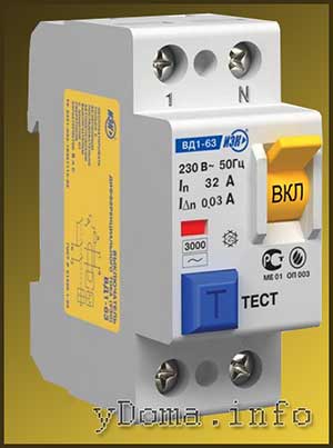
Externally, the RCD looks like a two-pole modular short-circuit protection circuit breaker, inside of which a release mechanism and a differential transformer are installed. By appearance The RCD differs from the machine only in the presence of an additional “Test” button, which is used to check the serviceability of the RCD. If you press it, the RCD will trip.
According to Ohm's Law, the current flows the same at any point in a closed circuit. Therefore, when connecting any electrical appliance to a household electrical network, the amount of current flowing through the neutral and phase wires of the cable at the entrance to the apartment is equal. This equality is what the RCD controls. But if a person accidentally touches the phase wire with his hand, and with the other part open area body touches a grounded conductive object, then the current in the phase wire will become greater than in the neutral wire by the amount of current flowing through the human body. The differential transformer will record this difference and the RCD will turn off the power supply.
IN modern apartments, in which all communication pipes are made of plastic, and the floors are made of non-conducting materials, accidental contact with the phase wire and grounded surface of a person is practically excluded. But from a more real case, when a person touches zero and phase wires at the same time, the RCD does not protect.
How to choose an RCD
The range of RCDs for household electrical wiring is small, and practically comes down to four types, differing in sensitivity, or rather the leakage current at which the protection is triggered. RCDs are produced for leakage currents of 10, 30, 100 and 300 mA. A current of less than 30 mA is not fatal to a person and, when flowing through his body, only causes painful sensations. Therefore, an RCD for an apartment is chosen for a leakage current of 30 mA.
RCDs are still different permissible current load, when choosing, you need to take an RCD designed for a load current equal to or greater than that of the machine. When the circuit breaker protection current is 16-32 A, an RCD with an operating current of 32 A is suitable.
Thus, for almost any residential electrical wiring, an RCD designed for an operating current of 32 A and a leakage current of 30 mA is suitable. Just an RCD with these parameters is shown in the photo above.
Death statistics from electric shock
99% of apartments in the country are not equipped with RCDs, and in statistical data there are no cases of fatal electric shock in the home. On average, per 1,000,000 people per year there are 2-3 cases of fatal electric shock, and they usually occur in production or on the street due to gross violation of electrical safety rules.
The need to install an RCD
RCD, like any additional device in the system, reduces its reliability. When installing an RCD, four additional mechanical connections appear in the electrical wiring, which, as practice shows, most often disrupt the operation of the electrical wiring.
In old electrical wiring, due to leakage currents in it, there is a high probability of false alarms of the RCD. Some electrical appliances can also cause false triggering of RCDs due to the nature of their design. In modern electrical wiring, through contact in electrical plug The metal part of the body of any electrical appliance is automatically grounded and in the event of a phase contact with the body due to an insulation breakdown, the circuit breaker will operate. In addition, it is worth noting that all portable household electrical appliances are double insulated.
Thus, existing protective measures even without an RCD, subject to basic safety requirements, reliably protect a person from electric shock in everyday life.
The analysis showed that installing an RCD is more a tribute to fashion than a vital necessity, leading to a decrease in the reliability of electrical wiring in general and unjustified costs.
For those who decide to install an RCD, it is possible to replace the circuit breaker and the RCD with one device that performs two functions at once - short-circuit protection and the RCD.
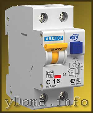
To select a differential circuit breaker, first determine the parameters of the short-circuit protection circuit breaker and the RCD according to the above method. Based on the obtained parameters, the type of differential machine is selected.
How to properly connect wires to an electric meter
When I clamped the wires into the terminals of the electric meter, before clamping I simply removed one and a half centimeters of insulation from the wires and inserted them into the terminal.
While editing this article, I realized that the connection could have been made more reliable. The terminals on the Mercury 200 meter are two flat plates between which the wires are clamped. The width of the plates is about 5 mm. Consequently, the opportunity to increase the contact area of the wires with the terminals was missed in a simple way. And now it’s too late to change it, since the meter is sealed.
The electrical wiring in my apartment is made with a wire with a diameter of 1.8 mm, therefore, if you bend the wire, as in the photo, it will freely fit into the meter terminal and thus the contact area of the wire with the terminal will double. In addition, misalignment of the contact plates in the terminals will be eliminated. In this way, it is advisable to connect wires to RCDs or circuit breakers if their connecting terminals are flat and the wire diameter allows.
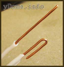
DIN rail for mounting
circuit breakers and RCDs
The circuit breakers for the electrical panel have been selected and it is time to install them. Currently, the most common method of fastening switching electrical devices, be it circuit breakers, RCDs, relays, transformers, sockets and many others, is fastening on the so-called DIN rail using latches.
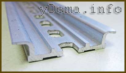
The name “DIN rail” came to us from Germany, the abbreviation DIN stands for Deutsches Institut fur Normung. DIN rail is standard for all European countries. In Russia, the DIN rail in accordance with GOST R IEC 60715-2003 is designated TN35. A DIN rail is a cast or stamped profile made of steel or aluminum with a width of 35mm. The length of the rail is selected based on the number and width of electrical switching devices planned for installation.
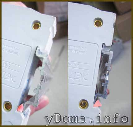
The DIN rail has gained wide popularity among electricians due to its ease of connection, ease of installation and removal from the electrical panel. It only takes a few seconds to install the circuit breaker on the DIN rail. You need to insert the switch with the groove behind the upper protrusion of the rail and press the lower edge of the switch. The spring-loaded latch on the switch will securely secure it to the DIN rail. In the photo the latch is highlighted in pink.
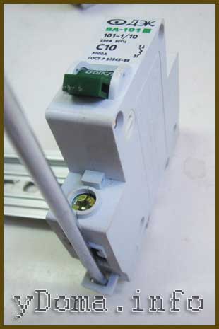
To dismantle the product from the DIN rail, simply insert the blade of a screwdriver into the special eyelet at the bottom of the product and move it to the side. The latch will come away and the appliance can be removed.
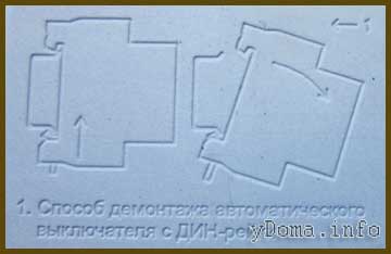
There are electrical appliances that can be dismantled without the help of a screwdriver. Here is a photograph of a diagram for dismantling an electrical appliance with fastening of such a design.
To prevent unauthorized movement, limiters are additionally installed on the DIN rail of electrical appliances. The DIN rail on the shield is attached directly to its rear wall using screws.
How to make and secure an electrical panel with your own hands
When I moved into the apartment, I moved the panel with the meter and plugs to another wall, since it was located on the passage of the corridor, and it could easily be broken by accidentally catching it. Back then, circuit breakers were not installed in apartments and better protection from a short circuit at that time there were automatic plugs.
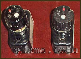
Therefore, installed plugs with fusible inserts, taking into account electrical diagram and the sections of the electrical wiring wire were replaced with automatic plugs with a protection current of 16 A. They worked reliably for twelve years, successfully protecting electrical wiring from short circuits, while simultaneously performing the function of a switch. By pressing the small red button on the body of the automatic plug, you could turn off the power supply, and to turn it on you had to press the button white. The electricity meter was mechanical, and despite the fact that it had worked for more than 50 years, it was in working condition. Therefore, I did not replace the meter.
For aesthetic reasons, it was decided to install an electrical panel with a meter and automatic plugs in a niche. To increase electrical safety, the standard metal shield was replaced with a homemade one made from a 5 mm thick fiberglass sheet. It’s not difficult to make an electrical panel yourself; just cut a plate out of a sheet of fiberglass the right size, mark the mounting points for electrical appliances and the points of holes for the passage of wires. Drill holes and tap threads at the mounting points. I used M4 screws for fastening.
On the wall in the niche, the electrical panel is fixed in the corners to four posts installed in the wall using mortar with M4 screws. In order for the threads of the racks to coincide with the mounting holes of the shield and to be at the same level, you must first attach the shield to the place of its planned installation and mark the points of the mounting holes on the wall. Then drill holes in these places with a diameter 4-5 mm larger external size racks, 4-5 cm deep.
Next, you need to secure the racks to the shield, fill the holes in the wall with a solution, for example rotband, and install the shield, squeezing out the excess mortar with the racks. Leave everything in this position for a day. Alabaster or gypsum can be used as a solution. But these solutions set quickly and therefore it is more difficult to work, but you won’t have to wait for days.
Repair of contacts connecting wires to the meter
Several years ago, the house was completed major renovation electrical wiring, including inputs to apartments. Replaced and electric meters electronic two-tariff type "Mercury 200".
Several years have passed since then, and suddenly the light bulbs began to wink periodically. At first I thought that this was the result of an electric welding machine, since there were renovation work. But at night, the lamps also began to blink. It became obvious that the problem was in the electrical wiring of the apartment. The wires in all the electrical junction boxes were twisted and soldered, so I immediately ruled out this reason. All that remains is to check the connection of the wires in the electrical panel.
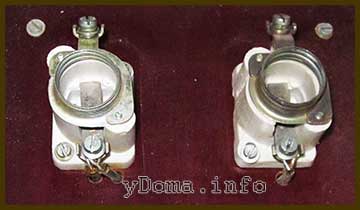
An external inspection of the electrical panel and the meter with automatic plugs did not reveal any violations. The protective covers from the plug holders were removed. The points of contact with the plugs and the connection of the wires were in perfect condition, although they had stood without maintenance for more than 12 years. Obviously, reliable contact was ensured by washers with growers and rings at the ends of the wires.
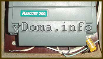
The electrical wires leading to the electric meter were covered by its housing. A professional electrician installed the meter in my absence and screwed up. Too lazy to drill mounting hole V in the right place and screwed the self-tapping screw into the nearest hole left from the fastening of the removed mechanical electric meter. As a result new electricity meter was very close to the bottom wall of the niche and blocked inspection of the electrical wires. In addition, the current supply cable coming from the panel in the entrance was not threaded through the holes in the meter's electrical panel, but was run next to it.
It was impossible to remove the cover covering the terminals for connecting the wires, since it was sealed; in the photo the seal is in the form of a cylinder yellow color. To inspect the wires, there was only one option left: to remove the electric meter completely from the panel.
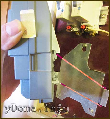
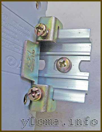
The Mercury 200 electricity meter was secured to the panel panel using a metal adapter strip. However, the fastening system of the Mercury 200 electric meter allows it to be installed in an electrical panel and on a standard DIN rail with a width of 35 mm. The adapter strip on the electrical panel was screwed with three screws, and the electric meter was secured to it using latches. The fastening elements are highlighted in the photo in a light tone. The arrows show where the clamps cling to on the bar.
When the sealed cover is removed, it is enough to insert the blade of a screwdriver into the holes marked with arrows and press the latches. It was impossible to remove the cover yourself; I had to remove the entire electric meter from the mounting panel. The electric meter was installed in a niche, and to gain access to the latches, we first had to remove the electrical panel.
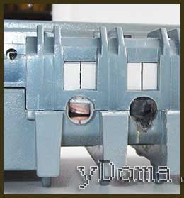
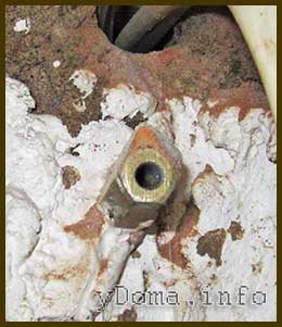
My assumption was confirmed; after removing the electric meter, a burnt phase wire was discovered in the output terminal of the meter. The wire was poorly clamped and when it moved under voltage, sparks jumped between it and the terminal. It was necessary to clean the wire and terminal contacts. To resolve the issue with the seal, I called the emergency service, which arrived a couple of hours later, and the electrician officially removed the seal. After that, to their joy, I let the electricians go and started not only repairing, but also modernizing the electrical panel. I have long been planning to replace automatic traffic jams with modern automatic machines, which were purchased in advance and were awaiting installation.
The wire got so hot that the plastic housing of the meter even melted a little where the wire came out of it. But fortunately this did not harm the electricity meter itself.
The clamping screws of the terminal were removed and, using a semicircular file, the upper and lower contacts of the terminal were cleaned to a shiny brass finish. The meter has now been repaired and is ready for further use.
The scope of work to modernize the electrical panel included the task of replacing automatic plugs with modular automatic machines.
Installation of electrical appliances on a homemade panel
The choice of the meter, circuit breakers and RCDs for electrical wiring has been made. The rules for connecting them have been studied, therefore, you can begin installing the selected electrical appliances on the panel.
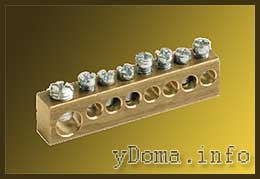
It is customary to connect the neutral N and grounding PL wires into separate groups using the terminal strip shown in the photograph. But I have repeatedly encountered a burnt neutral wire with this connection method.
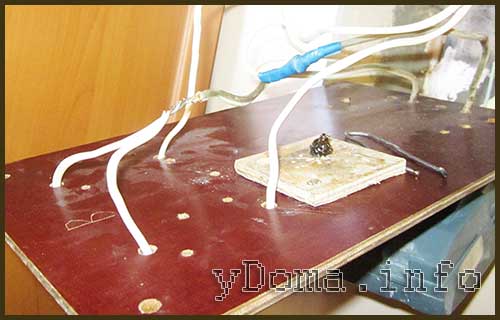
Therefore, I decided to connect the wires by twisting followed by soldering. The phase wire coming from the meter to two circuit breakers was branched by twisting two sections of wires and then soldering the twisted area. The neutral wire going directly from the meter to the electrical wiring was also branched in the same way. The connections were insulated with three layers of electrical tape and placed behind the shield.
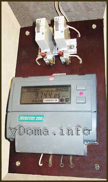
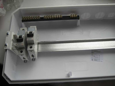
In place of the automatic plug holders, a DIN rail was installed with a length reserve of two standard sizes so that, if necessary, it was possible to install additional devices. There are two circuit breakers mounted on the DIN rail. Thanks to the installation of the electric meter slightly higher, the wires connected to it became accessible for visual inspection and it became possible to touch the wires in order to check the reliability of contact with the meter terminals by their heating. Since all the wires were hidden under the shield and only their ends were brought out to the front side for connection, the niche with the meter and machines began to look neat.

The electrical panel is still not a decoration for the hallway. Therefore, the niche was closed with a picture hung on a nail. All inspectors really like this solution.
Why on the neutral wire
It is unacceptable to install a circuit breaker
By e-mail I corresponded with Volodymir about the inadmissibility of installing a circuit breaker on the neutral wire of the electrical wiring. For those who want to understand the intricacies of this issue, I think its result will be useful.
Volodymyr: I'm currently installing an electrical panel in my apartment and a question has arisen. Why can’t separate machines be set to zero and phase, but only paired ones? Why “It is strictly prohibited to install a single circuit breaker on the neutral wire.”?
Answer: When installing separate circuit breakers on the neutral and phase wires, designed for the same protection current, in the event of an overload of the electrical wiring, only one of them is likely to work. This is due to the fact that circuit breakers have a variation in the magnitude of the operating current. If the machine installed on the neutral wire is triggered, then all electrical wiring, including the neutral wire, will be under phase voltage. The phase will reach the neutral wire through electrical appliances that are turned on at this time, for example, a TV in standby mode, a refrigerator. And if a person thinks that since the machine has worked, it means that the wires are de-energized and, therefore, safe, then he can start repairing the electrical wiring and accidentally come under dangerous voltage.
That's why it's impossible. You can install paired circuit breakers in household electrical wiring, but there is no point in this, only extra costs, since a twin machine costs much more. Therefore, the neutral wire is laid directly, and a machine must be installed on the phase wire.
Volodymyr: If during a short circuit the zero-machine is knocked out faster, and the short circuit phase-man-earth continues, then it will still knock out phase machine. Also, both can work approximately simultaneously. That is, the machine must be set to zero more powerful than the phase one. But there will be no disruptions to the network, only additional costs.
Answer: If the “phase-person-earth short circuit continues,” then the person will die before the circuit breaker on the phase wire is triggered. The lethal current through the human body is only 0.1 A, and a 10 A machine will only work when a current of more than 10 A flows through it. Therefore, the PUE categorically prohibits the installation of a separate machine on the neutral wire.
You can, of course, install a machine designed for a higher current on the neutral wire, but where is the guarantee that the machine will not fail? After all main value for any person his health and life! Therefore, even with the hypothetical possibility of causing harm to a person, they do everything to exclude it.
Volodymyr: I am just beginning to master electrical installation in practice, including using your recommendations. And I want to understand the technical side in order to better understand the recommendations of the PUE. So forgive me if I'm wrong somewhere.
There are two common situations:
1. Short circuit phase-man-earth or phase-earth. A phase machine will work here. Zero machine has nothing to do with it.
2. Short circuit phase-man-zero or phase-zero. A phase machine and/or a zero machine will work here. That is, if the phase machine does not work, then the zero one will break the circuit.
Accordingly, the circuit breaker to zero will not be a hindrance, but only additional protection when it is not possible to install a more expensive two-pole circuit breaker that cuts off the line completely. The only inconvenience, as you wrote, if during a short circuit only zero is knocked out, then we will not know whether the phase is knocked out.
Answer: Your reasoning is based on the assumption that the machine serves to protect a person from electric shock. But the machine is designed solely to protect electrical wiring from destruction if the current flowing through it exceeds the permissible limit. To protect people, an RCD is installed. The situations you described involving a person will not lead to the machine being turned off, since the person will die instantly if the current flowing through his body is more than 0.1 A.
According to Ohm's law, current can only flow through a closed circuit and in the event of a short circuit, it does not matter which wire is broken, phase or neutral. From this point of view, you can put one machine on the phase or neutral wire, or, if there is nowhere to put the money, sequentially, at least 10 machines on both the zero and phase wires. The wires will be protected. The machine is placed on the phase wire only so that when the machine is triggered, the possibility of a person coming under life-threatening voltage is completely eliminated.
Let me give you an example: a man decided to replace a light bulb in a chandelier and turned off only the switch, and not the machine, this is usually what they do. The wiring in the chandelier was old, and the neutral wire was touching the metal body of the chandelier. The man stood on the ground and, screwing in the light bulb, held the chandelier by the metal body with one hand. At this time, another family member decided to turn on an electrical appliance, whose insulation at the exit from the plug had frayed and the wires were short-circuited. A short circuit occurred, and only the circuit breaker installed on the neutral wire worked, and a phase appeared on the neutral wire of the entire apartment wiring. As a result, a person changing a light bulb can receive an even fatal electric shock. The machine can also work when the lights are turned on if the light bulb burns out at that moment.
PUEs are written based on accidents involving electric shock to people and it is impossible to describe all situations in which people were injured or died. You just need to follow the PUE and then the electrical wiring will never fail.
Legal issue
According to legal requirements, all metering devices must be sealed. Therefore, before breaking seals, it is imperative to obtain permission to do so from the management or electricity supply company. In an emergency like mine, you should call the emergency services. They have the right to remove the seal and issue a document confirming this fact.
When installing an electric meter, you must comply following rules. The wires supplying electricity from the entrance to the apartment should not have connections. The electric meter must be installed at a height of 0.4 to 1.7 m and must be sealed, regardless of whether it is located in an apartment or in the entrance of a house. The circuit breaker included in the electrical wiring in front of the electric meter is sealed only if it is installed in the apartment. The design of the machine installed in front of the meter in the apartment must provide for the possibility of sealing it.
After completion of the work, you must immediately invite a representative from management company or energy networks for sealing the meter, and, if necessary, the circuit breaker. The representative may require the presentation of a Certificate of emergency service and Passport for the electric meter.
An electrical panel in a private home, in a country house, in an apartment performs a double function: it provides input and distribution of electricity and creates safe conditions operation.
In some multi-apartment buildings, meters are located in switchboards stairwells. In this case, the shield is needed exclusively for RCDs and automatic machines. In other dwellings it stands in the living space. When upgrading the electrical network, you will need to take the shield so that it fits there.
Choosing an electrical panel for an apartment
Previously, before carrying out all the work on installing the electrical panel, a wiring plan is drawn up indicating all points of energy consumption.
Distribution boards are produced in a modular design, i.e. all devices have dimensions that are multiples of 18 mm, 36 mm, etc. Standard cases are designed to accommodate a multiple number of modules - 6, 9, 12, 18, 24, etc.
To install an electrical panel in an apartment, it is also necessary to take into account the method of laying electrical cables in the premises. There are two main types of electrical wiring used:
- external - laid on top of the plaster layer of the wall;
- internal - for this type of wiring, a special groove is punched in the wall with further cable laying.
- metal with a special color or heat-resistant coating;
- durable heat-resistant plastic.
Shields are produced in various configurations and dimensions:
- in frame design;
- collapsible;
- all-metal.
Complete set of electrical panels
You need to select an electrical panel taking into account the placement of elements and units, the number of power consumption points installed in buildings. How bigger building, the number of rooms, sources of consumption, especially since switching devices, protection, control and accounting devices will need to be installed in the electrical panel. It is necessary to similarly predict spare capacity in the event of an increase in electricity consumption.
Electrical panels are supplied as standard with:
- DIN - rail - a special strip for fastening devices inside the panel using fastening latches. The rail is made of an alloy that replicates the appearance of the plate and is fixed on the body of the electrical panel. If it becomes necessary to change the length of the DIN rail, its size is reduced by sawing off unnecessary sections with a hacksaw;
- vending machines - designed for automatic protection power supply systems from overloads and short circuits. The number of devices is adjusted depending on the load;
- distribution bus No. 1 – used for connection to switchboard zero exits. Bus No. 2 – combines all grounded wire terminals. There are two types of buses installed in electrical panels: closed and open. Tires closed view have protective insulating shields that protect against accidental contact;
- connecting electrical wiring;
- electric meter electrical energy(if necessary).
Basic Rules
When assembling and completing the electrical panel, several rules must be followed
1. The input circuit breaker must be two-pole for a single-phase network (220 V) and three-pole for a three-phase network (380 V)
2. Power is supplied to the upper terminals of the machine. The phase wires going to the lower terminals are connected to electrical groups room wiring. All circuit breakers and RCDs are powered using jumpers, the cross-section of which is larger than the cross-section of the outgoing (lower) wires
3. B electrical panel In addition to the circuit breakers, an RCD differential circuit breaker is installed. A group of sockets located in areas with high humidity(bath, kitchen, etc.)
4. It is highly recommended to install a voltage relay, which will protect the entire household appliances from network problems (any permissible voltage surges, zero burnout at the substation and interference from powerful electrical installations)
Connecting the electrical panel
After installing the electrical panel, all necessary devices, the cable connection is made. All supplied power supply wires must be signed to speed up the connection of the electrical panel.
The ends of the wires intended for connection are stripped of insulation and marked. The following are installed in the panel: a DIN rail and the circuit breakers are mounted on it. The order of installation of the circuit breakers: the input circuit breaker is installed first on the right side, then the RCD circuit breaker, and then the circuit breakers in random order.
When assembling an electrical panel, the rule must be observed - the input circuit breaker for a single-phase network is used two-pole, and for three-phase network three-pole.
The installation of the zero strip is done with the inclusion of the zero ends of the wires. The supply electrical wires are connected to the upper terminals of the machine, and the phase electrical wires of the electrical wiring groups from power sources are connected to the lower terminals.
Next, the supply electrical wires are connected to the upper input of the machine, and to simplify it, a single jumper is made, and all the terminals of the machines of this row are connected. In electrical panels, among other things, RCDs are used - differentiation machines, to which the electrical wiring of rooms with an increased concentration of water in the air is closed.
The power cable from the access panel to the apartment panel is usually laid using a three-wire power cable with the following markings:
- L – mains phase (red or Brown color isolation);
- N – neutral wire (blue insulation color);
- PE – protective ground wire (yellow-green insulation color).
The entire assembly of the switchboard must be carried out in compliance with the uniform connection rules for all devices installed in accordance with the technical specifications.
All machines must be connected to each other. This can be done using conductors - connecting their inputs in series, or using a ready-made connecting comb.
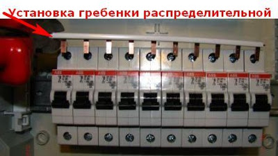
A comb is more reliable, although it costs more, but if you take into account the time that you will spend connecting all the machines, it is unlikely that a few tens of rubles are of such fundamental importance.
Connection diagram examples
Number of distribution boards
The number of panels in a house depends on its area, as well as on the complexity of power distribution throughout the building.
At the dacha - alone. For country houses and small mansions with an area of 150–200 sq. m; 1 is enough electronic cabinet installed at the electricity input. Inside the box there is a meter, a powerful input circuit breaker that controls the entire power supply circuit of the mansion, and a few smaller circuit breakers. Usually, one of them controls the electrical outlet network, another one controls the lighting network, while others have a narrow specialization and protect certain devices: a washing machine, electric stove, electric heater in the sauna and so on
A group of instruments is also located here. protective shutdown(RCD): one common one, working in conjunction with an input circuit breaker, and several additional ones, used for the outlet network and power circuits of individual devices. By the way, experts believe that there is no need to protect the lighting network using a separate RCD. Current leakage in this area is practically impossible, and therefore, to ensure its safety, one device mounted on the input is completely sufficient.
There are several in the house. For large mansions, one shield at the input will not be enough. Due to the large length of the wiring, the circuit breaker at the electricity input in the event of an emergency can operate with a significant delay or not operate at all.
The following scheme is used: 1 common distribution panel at the entrance of electricity into the house plus one or more similar devices on any floor.
Inside the first electrical cabinet a meter, an input machine and a general RCD are installed. Other distribution panels house automatic switches for the socket network and lighting network for this floor, as well as a group of RCDs that monitor the same areas.
This scheme allows you to minimize the distance from protective devices to electrical appliances, and also, in the event of a breakdown, not the entire house is de-energized, but only one floor or even a certain room. And it also simplifies the search for the precondition for triggering the protection device.
If you ask any person inexperienced in electrical engineering what is in an electrical panel, the immediate answer will be - automatic machines. Although, in addition to circuit breakers (this is the correct name for machines), there may be RCDs, differential automata, load switches, contactors, pulse relays and much more. The purpose of this article is to find out how to select automatic circuit breakers from the whole variety of modular devices, what they are intended for, how to choose them correctly, how to connect the circuit breaker in the panel and what to do when triggered.
At first glance, it may seem that an ordinary person, completely unfamiliar with engineering in general and electrical engineering in particular, does not need to know anything about circuit breakers, because the wiring in an apartment or house was done by professionals. It is possible that this is so, but what will a person do if the voltage suddenly disappears in the entire apartment or house or in some part of it? Of course, the person will open the panel, look at which machine was “knocked out,” and again move the lever to the “on” position.
It is in this action that lies main mistake « ordinary people“, because before turning on a triggered modular device, you need to understand the reason for its triggering. Therefore, you should not be surprised when, after turning on again, immediately or after some time, a second shutdown follows. Without eliminating the cause, you should never re-enable modular devices, including circuit breakers (hereinafter referred to as circuit breakers). This can lead to dire consequences both for human health and life, and for property.
The point is that on different devices protection are assigned their own functions, therefore the reasons for the operation of automatic circuit breakers and residual current devices (RCDs) are completely different. And in most cases this does not concern the quality of installation electrical wiring. Of course, an experienced electrician will always find the reason. But if incidents with electricity occur at night or on a weekend, then not every electrician will agree to quickly solve the problem, and if he does, the owners will have to pay well out of their own pockets for the urgency.
As the electricians themselves say, 50% of cases of protection devices tripping are trivial and occur through the fault of the owners themselves, and electrical wiring has nothing to do with it. That is why elementary basic knowledge about protection devices, their purpose and rules for responding when they are triggered will be very useful. The authors of the article will try to explain everything in understandable language, without going into the weeds technical nuances, which will be of interest only to specialists, but not to “ordinary people”.
What is a circuit breaker and what is it for?
A circuit breaker (circuit breaker) is a device that is designed to switch (in other words, turn on and off) an electrical circuit. That is, what is meant here is that you can manually turn on and off an electrical circuit using a lever.
However, the name itself - circuit breaker - indicates that the machine should automatically turn off the load. In what cases does this happen?
- When the circuit protected by the circuit breaker flows a current that exceeds the permissible limit. And the greater the current excess, the faster the shutdown occurs.
- When very large currents arise in the protected circuit that are unusual for the load - the so-called short circuit currents. In these cases, the machine reacts very quickly - within a fraction of a second.
Overload can occur when, in one circuit protected by a circuit breaker, one powerful load is turned on at the same time, for which neither the cable nor the circuit breaker is designed, or several powerful loads. For example, in one socket circuit of six sockets, an electric kettle, iron, electric fireplace, microwave oven, steamer and hair dryer are simultaneously turned on. Naturally, with such a load, the current will greatly exceed its rated values, this will cause the wires to heat up greatly, which can lead to melting of the insulation and subsequently to a short circuit. The machine should not allow this to happen and should turn off the circuit before the wires get too hot.
Short circuit currents can occur when in any device there is an insulation breakdown on the housing or a phase and neutral conductors. According to Ohm's law, the lower the resistance, the greater the current. The higher the current, the more heat is generated, which leads to melting and burning of the insulation. Short circuit is the most common cause fires in electrical wiring. That is why the machine is entrusted with very important function– instantly respond to short circuit currents, that is, to currents that are many times higher than the rated ones. The reaction time of the machine must be such that the wires do not have time to heat up to dangerous temperatures.
From all of the above, one important conclusion follows: the circuit breaker is designed to protect wires, cables and various components included in the circuit. electrical devices from overload and short circuit. There is not a word about the person. Therefore, you should understand the main thing - the machine does not save a person from electric shock. The machine saves cables and wires.
Let's give an example. Let’s say that the lighting circuit in an apartment is protected by a 10 Ampere circuit breaker and a person, while changing a light bulb in a lamp, accidentally touched a live phase conductor and touched the grounded body of the refrigerator with the other part of his body. An electric current begins to flow through the human body, which depends on the resistance - the greater it is, the less the current. In calculations, resistance is taken human body equal to 1 kOhm, which means the current will be I=U/R=220/1000=0.22A=220mA. For a fatal electric shock to a person, 80–100 mA is enough, and the machine has a rated current thousands of times higher. Therefore, we repeat - the machine gun does not save a person from the damaging factors of electric current. Of course, a triggered circuit breaker can save someone's life if it prevents the electrical wiring from catching fire, but direct impact It does not save an electric current on a person.
Briefly about the “inner world” of the machine
Circuit breaker is complicated electromechanical device. Some modern models vending machines are equipped with electronic units that more accurately monitor flowing currents, but in this article we will look at the device of the “classics”. The machine is shown in cross-section in the following figure.
There are terminals at the top and bottom of the machine, and it is always accepted that the input is at the top and the output at the bottom. The upper terminal is rigidly connected to a fixed contact, and the lower terminal is connected to a thermal release, which is a bimetallic plate that bends when heated. The end of the bimetallic plate is connected by a flexible conductor to one of the solenoid terminals of the electromagnetic release. The other output of the solenoid is connected by a flexible conductor to a moving contact.
The release mechanism is designed in such a way that the moving contact is spring-loaded and securely fixed both in the on and off state. In addition, the springs allow switching to be carried out very quickly, which avoids severe burning of the contacts during a spark or arc discharge, which can occur precisely at the moment of shutdown.
The release mechanism can be activated in three ways:
- Turning on the machine, that is, when the moving contact is pressed against the stationary contact, is possible only manually, through the release mechanism control lever. You can also turn off the machine manually.
- When there is an overload in the circuit, a current that exceeds the rated current passes through the bimetallic plate of the thermal release, heating it too. Under the influence of temperature, the plate bends and presses on the lever of the release mechanism, which turns off the machine. The higher the current overload, the faster the plate heats up and the faster the mechanism operates.
- If short circuit currents occur in the circuit, then the current passing through the solenoid of the electromagnetic release induces a magnetic flux capable of drawing the spring-loaded core of the solenoid inward, which, in turn, acts on the moving contact and opens the circuit. The reaction time may be good machines be thousandths of a second.
At the moment of disconnection, a spark discharge may occur between the moving contact, which ionizes the atoms of gases that make up the air. Ionized gas is a good conductor, so it can catch fire electric arc, temperatures in which can reach several thousand degrees. Naturally, such a thermal effect will very quickly burn out the circuit breaker if special measures are not taken.
The machines always have a special arc chute, which is a set of copper or copper-plated steel plates that are insulated from each other. When an arc lights up, it forms a powerful magnetic field, which induces an EMF in the plates, which also forms its own magnetic field opposite in polarity. These fields interact with each other, the arc is drawn into the plates of the arc chute. The plates “shred” the arc into pieces and cool it, as a result of which it quickly goes out. When an arc burns, it forms a large number of gases that freely exit the machine body through a special hole located below the arc extinguishing chamber. This process may take a fraction of a second, but even this time is enough for the spark discharge or arc to “burn” the contacts a little.
Over time, with frequent switching on and off of machines, the contacts burn out. There were times when the contact pads of circuit breakers were made of electrical silver; there are such devices now, but they are not used in household electrical wiring. Therefore, there is no need to “click” the lever of the machine unnecessarily, since with each action there at least a spark discharge occurs, causing erosion of the contacts. Automatic machines are designed mainly to protect cables or wires, and for switching there are special devices - load switches, called switches in Russian.
How to choose the right circuit breaker
Before installing a circuit breaker in an electrical panel, it must be selected correctly so that it matches both the cable and the nature of the load. Therefore, we will consider the main characteristics of modular machines, which are always indicated on their labeling. For a specialist, the marking says a lot, but for “ ordinary person" doesn't say anything. Therefore, you need to learn to read it, especially since there is nothing complicated about it.
Educational program on marking machines, selecting the right model
The figure shows typical markings for all circuit breakers. Let's look at all the points one by one and at the same time comment on which machines are needed for various purposes.
Trademark
At the top of the front panel of the machine it is always indicated trademark, which in other words means the manufacturing company. For security devices, this is of great importance, since it is better to choose a machine from a well-known brand. These are: ABB, Legrand, Hager, Merlin Gerin, Schneider Electric, IEK, EKF. When choosing a specific model and series, it is better to consult a good (not housing office) electrician.
Rated voltage and frequency
If the machine has the inscription 220/400V 50 Hz, this means that this device can operate in both single-phase and three-phase circuits alternating current with a frequency of 50 Hz. Most machines used in household wiring have this capability.
Rated current
This is one of the main characteristics, which indicates what maximum current in amperes can flow through the machine for a long time without triggering it. It is designated I n. If the current becomes 13% higher than the rated current, i.e. I=I n *1.13, then the thermal release starts to operate, but its response time will be more than an hour. Upon reaching I=1.45*I n the response time of the thermal release will be less than an hour and the higher the current, the less time triggering.
The rated current of the machine must always correspond to the cross-section of the cable or wire of the circuit it protects, but not to the load power. The machine should not allow them to overheat when electric current flows, however, real life the opposite often happens.
For example, a family acquired a washing machine and, when connecting it to an existing outlet, after a while the machine in the driveway switches out, since the total load turns out to be higher than it can tolerate. An electrician from the housing office came and offered an “ingenious” solution to replace the machine with another one with a higher rated current. For example, there was a 10 A circuit breaker in the panel and it is proposed to change it to 16 A, or even 25 A, to make it “more reliable”. The machine is being changed and, to the delight of the owners, it actually stopped knocking out when the washing machine was running. And the wiring is made with aluminum wire with a cross-section of 1.5 mm2, which is far from uncommon in houses built during the USSR era.
Naturally, during peak loads the wire will overheat and its insulation will melt, but the machine will not react in any way, since its response threshold is much higher. Unfortunately, such situations are far from uncommon. And the owners will be very lucky if there is no fire, but a short circuit, which will make the machine work.
It should be clear simple rules, which will help you choose the right machine that is guaranteed to protect the wiring from overheating.
- The cross-section of the cable or wire must correspond to the load.
- The rating of the circuit breaker must correspond only to the cross-section of the cable or wire, but not to the load.
The table below shows the correspondence of the section copper cable or wires and rated currents of circuit breakers. In any case, it is necessary to be guided by precisely this correspondence and nothing else. No exceptions or arguments like “I’ve done this a hundred times.”
The table shows that the machine does not allow you to use all the capabilities of a cable or wire for passing electric current, but limits them. And this was done intentionally, the circuit breaker is a kind of “weak link” that will not allow the cable or wire to “strain” too much, which, from a safety point of view, is very useful.
The rated current circuit breakers are 1A, 2A, 3A, 6A, 10A, 16A, 20A, 25A, 32A, 40A, 50A, 63A.
Time-current characteristic
Before the value of the rated current in the marking of the machine there is a letter index, which reflects the time-current characteristic (VTC). It is unknown for what reason, but, from the authors’ point of view, this is not given enough attention. Let's figure out what this characteristic is.
The figure shows a graph of the dependence of the operation time of the machine on the multiplicity of the flowing current to the rated current, that is k=I/I n. The graph is divided into three colored zones: green, blue and yellow, which correspond to the time current characteristics B, C and D. The following conclusions can be drawn from the graph:
- When k is greater than 3 but less than 5, the machine belongs to category B.
- When k is greater than 5 but less than 10, the machine belongs to category C.
- When k is greater than 10 but less than 20, the machine belongs to category D.
What does this mean in human language? The graph shows that in any category of machines, the greater the multiplicity of the flowing current in relation to the rated current, the faster the operation will occur. Circuit breakers with VTX category B react fastest to overcurrent, followed by circuit breakers of category C, and then D. There are also circuit breakers with characteristics K and Z, but they are not used in apartment and house wiring.
It is worth noting that the graph is given for certain external conditions, namely ambient temperature +30°C. When the temperature rises, the machines will operate at slightly lower currents, and when the temperature decreases, on the contrary, at higher currents. This difference is not so significant, but it still exists. The operation of circuit breakers is greatly influenced by their “neighbors” on the electrical panel, which, heating up when electric current flows through them, heat both the air inside the panel and the nearby equipment. That is why experienced electricians try to choose models of electrical panels that have many free space inside and when assembling them, they do not try to fill them with modular equipment “to capacity.”
The question arises: why divide circuit breakers into categories according to their performance characteristics? After all, you can simply make a device that will simply respond by turning off when the flowing current exceeds the rated one. But it's not that simple. Some types of electrical loads, when turned on, consume currents that are much higher than when they are running. For example, the electric motors of a vacuum cleaner or refrigerator compressor can consume 3-8 times the rated current at startup. If the machines react to such an excess every time, then life will turn into a living hell - every time you turn on the refrigerator, the machine in the panel vibrates. That is why thermal releases are used in automatic machines, which have a certain inertia, which allows for short-term excess current without leading to overheating of the wires. In any case, the thermal release is configured in such a way that it turns off the circuit before the cables and wires enter a dangerous mode.
In the electrical wiring of apartments and private houses, circuit breakers from categories B and C are used. When choosing a specific model, the nature of the load should be taken into account. For active loads, that is, those that do not consume high currents when starting, you should choose machines with VTX type B. This applies to lighting and socket circuits. Reactive loads will already require machines with VTX type C. These include refrigerators, air conditioners, washing machines and dishwashers, home workshops where power tools are used.
Unfortunately, it is very difficult to find type B circuit breakers in electrical supply stores. This is due to the fact that there is low demand for them. The lion's share of machines sold are VTX type C. But the authors of the article strongly recommend that you spare no expense and use type B machines for active loads. Even if you have to order them and wait for some time. The fact is that by combining circuit breakers with characteristics B and C, it is possible to achieve selectivity in the operation of protection devices.
Let's give an example. Let's say an incandescent lamp in one of the lamps has burned out, but the spiral has closed. Surely everyone has encountered such a situation when, when you turn on the light, the lamp flashes and immediately goes out with a characteristic click and at the same time knocks out the machine. It’s good if the machine, which only protects the room’s lighting circuit, is triggered, but it could happen that the machine located in the access panel is knocked out. Moreover, it happens that the machine guns in the apartment panel did not react, but the entrance one did. If this happens, it means that selectivity is poorly organized in the organization of electrical wiring.
The main principle of selectivity is that the protection devices closest to the source of the problem should operate first. If for some reason they do not work, then other devices located higher in the hierarchy must respond. In the described case with a lamp, you can install a machine with VTX type B on the lighting circuit, and install a machine of category C in the driveway panel. Then, when the lamp spiral is closed, the more “fast” machine of type B will work first, while the driveway machine is “stupid.” In this case, its slower response is beneficial, since it will not turn off the entire apartment.
Rated breaking capacity
This characteristic can also be called the ultimate switching capacity (UCC). PKS shows at what maximum current In the event of a short circuit, the machine will still be able to open the circuit at least once (and this will most likely be the last) time. Standard PKS values are 4.5 kA, 6 kA, 10 kA. For household use 4.5 kA is quite enough, but if the substation is located nearby, then it makes sense to use machines with a 6 kA PKS. Circuit breakers with PKS 10 kA are used only in industry.
Current limiting class
This characteristic has three values – 1,2 and 3, and if this marking is not present, then the machine belongs to class 1. It shows how quickly the machine will react to the appearance of short circuit currents. If a thermal release can “tactfully wait” when an overload occurs, then an electromagnetic release must act “decisively and boldly” when a short circuit occurs. The current limiting class precisely reflects the degree of “decisiveness” of the machine and its reaction time.
Class 1 opens the circuit in one half-cycle, which is approximately 10 ms in time, class 2 - in ½ half-cycle (5-6 ms), and class 3 in 1/3 of the half-cycle (3 ms). Naturally, the higher the class, the better, but also more expensive.
Number of poles
In modern apartment or house electrical panels, modular circuit breakers are used that have 1, 2, 3 or 4 poles. Single-pole and two-pole circuit breakers are designed to protect single-phase circuits, and three- and four-pole circuit breakers are designed to protect three-phase circuits. According to the number of poles, circuit breakers occupy the number of spaces (modules) in the electrical panel. One place is 17.5 mm.
Video: How to choose circuit breakers
As noted above, modern circuit breakers used in household electrical wiring are modular equipment, which, along with other control, switching, metering and protection devices, have housings standard sizes in length and height, and the width is always a multiple of one module (place) equal to 17.5 mm.
All modular equipment in electrical panels is mounted on a 35 mm wide DIN rail using a latch. To install, simply snap the machine onto the rail, and then move it left or right to the desired position. And to remove it you will need a straight-blade screwdriver, which you need to pry and pull up the spring latch.
To install and connect a circuit breaker to an electrical panel, you will need a standard set of electrical tools:
- Set of screwdrivers with both straight and Phillips slot. You should pay attention to which screws and which slots are used in the terminals of the machine. There can be two options: a cross-shaped Philips type (numbered in the figure 2) or a cross-shaped Pozidriv type (numbered in the figure 3). They are designated PH or PZ, respectively.
- Pliers of various sizes.
- Wire cutters or cable cutters.
- Insulation stripping tool - stripper.
- If they will be used for connection stranded wires, then you will need a tool for crimping the tips - a crimper.
- Indicator screwdriver.
We will describe the process of installing and connecting a circuit breaker in an electrical panel.
| Image | Description of process steps |
|---|---|
 | The electrical panel is completely de-energized, and measures are taken to prevent unauthorized switching on of voltage. indicator screwdriver The absence of voltage in the panel is checked. |
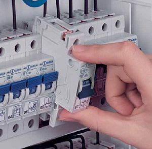 | The machine of the selected rating snaps into place on the DIN rail. |
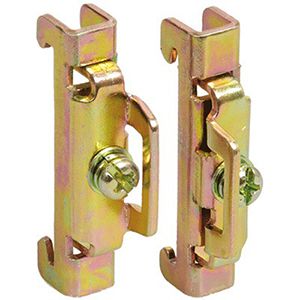 | If there are empty spaces to the left and right of the machine, then it is advisable to use special limiters that prevent the equipment from moving left and right along the DIN rail. |
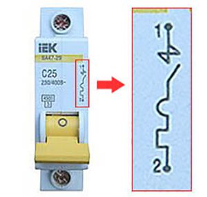 | When connecting a single-pole circuit breaker, the phase from the input device or RCD (individual or group) must be supplied to the upper terminal, and the phase of the protected circuit must be supplied from the lower terminal. |
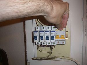 | When connected two-pole machine phase should be supplied to the upper left terminal, and zero to the right terminal. The phase of the protected circuit should “leave” from the lower left, and zero from the right. |
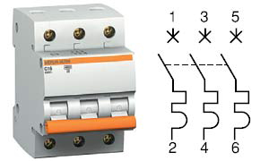 | When connected three-pole circuit breaker The upper terminals must be supplied with phases in the order they appear from left to right A, B, C (L1, L2, L3). Accordingly, the phases of the protected circuit must “leave” from the lower terminals in the same order. |
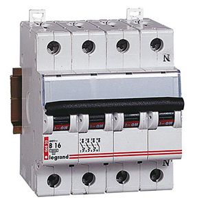 | A four-pole machine is connected in the same way as a three-pole machine, only a neutral wire is added - the one on the far right. |
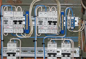 | Suitable wires and wires of the protected devices are laid in the electrical panel. electrical circuits to the corresponding circuit breaker terminals. Incoming ones are routed to the upper terminals, and outgoing ones to the lower ones. The only way! When laying, you should use existing bundles of wires. If necessary, the laid wires are tied to the bundles with plastic clamps. |
| If the circuit breaker is located next to others in the electrical panel and all of them “distribute” one phase or a phase together with zero, then it is advisable to use special comb buses, which, like circuit breakers, are one, two and three-pole. | |
| If there are no combs, you can make jumpers from the PV3 mounting wire and NShVI lugs (2), intended for crimping two wires. You cannot place two separate wires under the terminal of the machine. | |
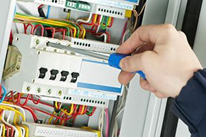 | After checking the installation compliance schematic diagram electrical panel, the wires are placed in the previously released terminals of the machine and clamped with a screwdriver with a force of 0.8 N*m. There is no need to try to tighten it as hard as you can, as this can lead to breakage of the machine body. |
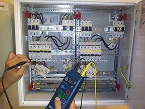 | Voltage is supplied to the electrical panel, all protection devices are turned on, an indicator screwdriver or a multimeter is used to check the presence of voltage at the input and output of the machine. |
 | The insides of the electrical panel are covered with a protective cover - plastron. A marking is placed on the circuit breaker indicating that it belongs to the protected circuit. Marking is also done on the plastron. |
Video: Circuit breakers - polarity and connection diagrams
What to do if the circuit breaker in the electrical panel has tripped?
If a circuit breaker trips during operation of the electrical wiring, there may be many reasons for this. Therefore, there is no need to rush to immediately turn it back on, but try to find out the source of the problem. In this case, you should be guided by the following:
- Any shutdown of the machine causes strong heating of its internals, especially the bimetallic plate of the thermal release and the solenoid. Before turning on the load, you need to allow a few minutes to cool down.
- While the machine is cooling down, you need to walk around the apartment or house and inspect all the sockets, switches, lamps, and powerful consumers of electricity. The smell of burnt insulation, darkening from exposure to fire, and hot plugs can tell a lot and point to the source of the problem.
- If everything is in order with selectivity in the electrical panel and only one circuit breaker has worked, protecting a specific circuit, then the task is simplified, since it is necessary to inspect only the consumers of only this circuit. It is much worse when the input machine worked, and others “ignored” the problem. Then you will have to turn off all the lines protected by circuit breakers, turn on the input machine and sequentially turn on all the circuits, one at a time. After turning on any circuit, you must give certain time excerpts and at the same time inspect all electrical appliances that are connected to the machine.
- If at sequential connection If one of them is triggered or the input machine is turned off, then the source of the problem has already been localized and the problem must be looked for in a specific circuit. This could be some kind of faulty consumer of electrical energy, a burnt-out lamp with a shorted filament, melted insulation on some section of the wiring, and much more. To find out what’s wrong, when the machine is turned off, turn off all electricity consumers in this circuit, and then turn on the machine. If it works, then the problem is in the wiring and you cannot do without the help of specialists. If not, then all consumers must be connected in series, which will help identify the faulty device.
- Disabling a machine in a particular line or input line can cause a very large load. For example, simultaneously included washing machine, Dishwasher, air conditioning and electric oven. The input machine may not be designed for such a load and therefore turns off the circuit. In this case, it is necessary to divide the operation of powerful electrical appliances over time.
- Hot summer weather combined with high loads may also cause the protection devices to trip.
- And the last reason is a malfunction of the circuit breaker itself. It is possible that before this it was triggered more than once by increased currents, briefly endured short-circuit currents, and repeatedly extinguished the arc. All these influences, unfortunately, affect the life expectancy of the machine not in better side. With the plastron removed, you can inspect the inside of the shield. A faulty machine can be identified by a melted body, burnt terminals and other signs. Simply replacing the circuit breaker may solve the problem.
- A circuit breaker is designed to protect the cable or wire, not people.
- The rated current of the machine must strictly correspond to the cross-section of the cable or wire being protected.
- In circuits with active loads, it is better to use machines with a time-current characteristic of category B, and with reactive ones, which have high starting currents– category C.
- A proper combination of circuit breakers with VTX B and C will ensure selectivity.
- When any circuit breaker trips, you must first identify the source of the problem. If you can’t do it yourself, you should call a specialist.
Conclusion
Reliable and safe electrical wiring for you!
To understand how to connect a machine in a panel, you need to familiarize yourself with the minimum requirements for electrical safety and fire protection. Also, knowledge of the basics of electrical engineering will be needed to calculate the required load from electrical appliances. It is important to select the type of electrical appliance, its response rating and the number of safety devices.
Purpose of electrical protection
To understand how to connect a machine in a panel, we need to familiarize ourselves with its purpose and types. The electrical panel contains all the equipment for distributing power to household appliances. Here there are terminal blocks, an electricity meter, an RCD device, automatic devices, and relays.
The equipment is held in place by a DIN rail made of conductive material and grounded at one point. They try to place the electrical panel at the entrance to the apartment or on the street side in a private house. The machine itself is a complex technical device. It is subject to certain requirements, depending on the purpose of the device.
A modern automatic meter protects wiring and equipment from short circuits and can even protect people from electric shock. It is prohibited to make homemade fasteners for the device in the panel in order to comply with safety rules when performing work on live devices. A specialist with the appropriate access group knows how to connect the machine in the panel. But if contacting a specialist is expensive and not profitable, then you can perform the replacement yourself.
It is also important to know how to connect the machine in the panel before purchasing and installing household appliances. So, more powerful ones are chosen for heaters safety systems, and for low-power devices you will need to add separate machines. For the latter, they install electronic ones. It is often advisable to install an RCD to provide high degree reliability of protective devices.
In most cases, electricians provide standard scheme connections of live wires - from above. However, often the meter box is installed by specialists who have nothing to do with electricity, and they supply the phases from the bottom of the machine. Therefore, before replacing failed devices, it is imperative to measure the voltage supply with a working voltmeter.
General information
The meter box in apartments contains a two-wire circuit for connecting electrical appliances. It is simple and contains a supply wire - “phase”, and a discharge wire - “neutral” or “zero”. Modern standards require the use of “grounding” to protect against short circuits. Devices such as washing machine, refrigerator, electric oven, must be connected using a three-wire circuit.
The general designation of the ground wire is yellow-green stripes. To connect the machine, it does not matter which terminal the phase wire is connected to. But it is recommended to connect it from above so that the next inexperienced specialist does not get caught in the current by grabbing the wire from the bottom of the machine out of habit. Before any work, it is required to turn off the input switch, but many electricians perform work under voltage. 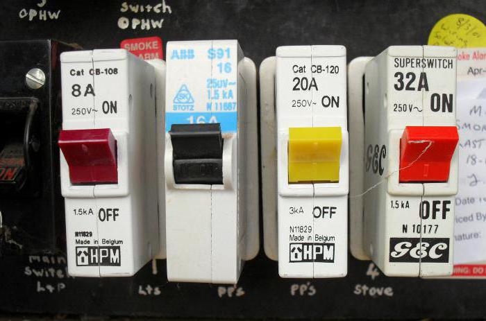
Wiring and connection must be carried out by a specialist with appropriate education and approvals. Understanding the nuances of installing some machines is not easy, especially if the consumer decides to install a separate switch for each socket and light bulb. Some organizations can provide a ready-made electrical panel assembly. But in this case, it is necessary to provide for the possibility of installing additional machines in the future if you want to change the overall electrical circuit.
To install and connect the machine you will need:
- Tools: wire cutters, flat and Phillips screwdrivers, multimeter.
- A wire designed for the household appliance used must have a cross-section that is twice the load. Installation is carried out in an already installed panel, so the DIN rail is not taken into account.
- The machine must have standard fastenings. The wires are placed in a corrugated hose to protect them from mechanical damage.
The insulation is removed from the cable, the length of the stripped wire is selected to be no more than 10 mm, so that the exposed parts are out of reach for hands and do not touch metal parts. Grounding is recommended. In older houses it may be completely absent. But for your own safety you need to install it.
To connect the “ground” in the panel, a common open terminal block is used for each supply wire. The outlet conductor has one larger cross-section. “Neutral” is also recommended to be performed with one block, but closed type. It often contains potential that is dangerous to human life. starts by connecting the ground wire, then the neutral. Finally, a phase one is installed. 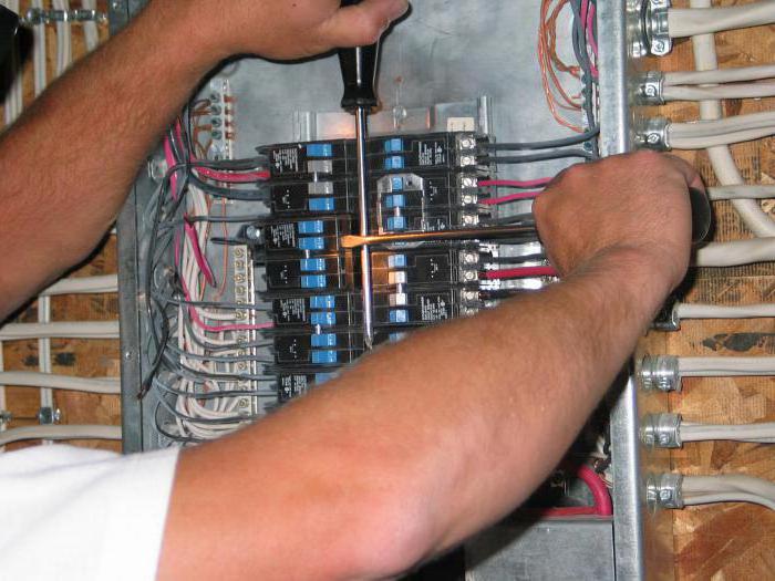
If there are several machines, jumpers are used, which begin to be installed from the input switch. A hose corrugated inside the shield is needed only for non-standard cable laying, when there is a risk of damage. Corrugation is not applied to short sections.
A replacement for jumpers is a common distribution plate, available for sale at any electrical store. To protect contacts from contact, a box for the machine made of plastic or other dielectric is used.
Device selection
The load on the machine should be less than the calculated one. 10, 16, 20 amperes are in demand. Higher ratings are usually used for boilers, house heaters, and ovens. For standard devices 10 amperes are suitable: PC, TV, iron or hair dryer. However, if several loads can be connected to one device, then the resulting value is obtained by adding all the ratings. 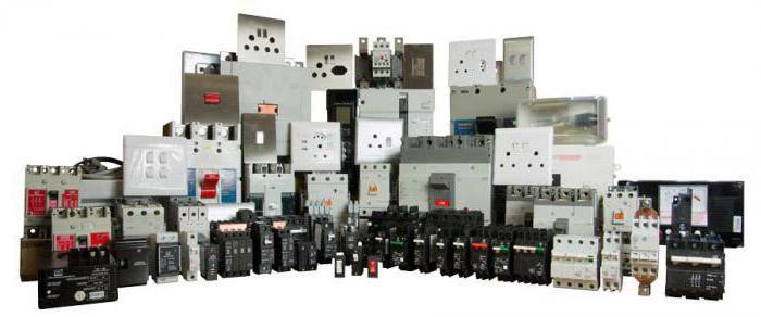
It is not recommended to use many devices, sockets, and lighting lamps on one machine. If one link fails, the socket can melt without turning off the fuse. So a 2-amp household appliance can start drawing 5 amps if there is a fault in the circuit board. A circuit breaker rated for 16 amps will not work. Even the insulation on the wires can melt.
Therefore, before choosing a machine, it is recommended to consult with an electrician on choosing the type protective device. They differ in response speed, purpose of protection, connection, internal device, number of phases. For installation in a panel, the phase wire is supplied from the side of the fixed contact; the marking is often already indicated on the body of the machine.
Switch types
The design of a circuit breaker depends on its type: the response speed can be milliseconds for magnetic switches and several hours for circuit breakers with a bimetallic plate. The letter in the designation matters when choosing a protective device. For the house it is recommended to install types B, C.
Z classes are rarely found in everyday life (for electronic devices), D (for electric motors and inductances), A (for long conductors). Experienced electricians recommend combining machines with RCD devices (residual current devices) or using automatic circuit breakers. There are electromechanical and electronic protection. The second is less reliable and quickly fails; tracks and internal elements burn out under significant overloads. 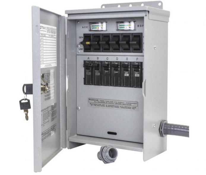
When choosing the type of machine, it is recommended to take into account that the current rating through the wiring cross-section must exceed the possible overload and the maximum value of the switch. If the machine has a high response speed and sensitivity, then it will have a higher cost. However, it will not be reliable in all cases; erroneous responses to increased loads are possible.
Such a problem can only be identified in each specific case when analyzing the type of household appliance and additional parallel loads connected simultaneously to the network.
Design features
The circuit breaker device is of the following types:
- Electronic principle of operation.
- Electromechanical.
- Electromagnetic.
Most often chosen for home budget options execution of machines electromagnetic principle actions. The main working part is: It is advisable to choose a switch in proportion to the cost of the equipment. For ordinary functions, ordinary automatic machines are suitable, but if specific electrics are used, it is recommended not to skimp on protective equipment.
Fuses are used in production to this day in particularly critical components of the electrical circuit. The RCD primarily protects the human body from electric shock. From the basics of electrical engineering it is known that the current in series circuit same. The principle of operation of the device is based on comparing the phase current and neutral wires. The so-called one that occurs at the moment of a person’s defeat is revealed. 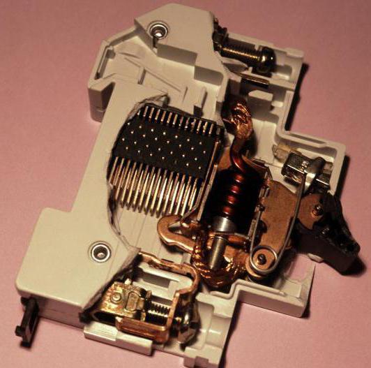
However, RCDs can often trip erroneously when operating large inductances or capacitances. The operation of the machine is not affected by the method of connecting the phase and neutral in a single-pole design. The overload is measured, the potential difference is not taken into account.
Common mistakes
Upon completion of the work, we received installation in which it was completed according to all the rules. But the machine still goes off for no apparent reason or the equipment in the house does not work. This result is possible if certain steps are performed incorrectly.
A simple and solvable problem is the lack of contact in the terminals of the machine. This is possible when the wire insulation is not sufficiently removed and the clamping jaws come into contact with the dielectric part. The bare end should protrude slightly beyond the boundaries of the machine, and they should be protected by a dielectric housing placed over the switch.
Let’s assume that the panel in the apartment has a non-standard connection diagram, and during installation the neutral of the devices could have been connected to the ground conductor. This type of malfunction occurs only for beginners, but it can lead to the failure of an expensive device: TV, PC, charger or other type of equipment.
Burnout of the pads can occur when powerful devices are connected to the network, when the wire core on the machine is not stretched and has weak contact. A large load produces a spark, as a result the device heats up in this place, but does not knock it out. Long-term operation in this mode leads to the fact that the plastic begins to melt until it ignites or short circuits to a grounded case.
Arises typical mistake when the cross-section of the connected wires differs slightly. In this case, loose contact is possible, due to which a spark will occur. This will ultimately result in the result described above. To avoid fire, you need a non-flammable switchboard. Electrical installation is erroneous when connecting several sources of different power to one machine. The higher the difference between the most powerful device and the weakest, the less reliable contact is obtained in the sponges.
Ease of installation is achieved by forming the wires in the form of a Y-shaped arc at the connection point. This makes it easier to hold the conductor while tightening the terminal. Before making the connection, be sure to turn off the input switch, if possible.
To connect machines, you can use your own jumpers of the same cross-section. However the best solution there will be a common bus with standard fastenings. When tightening single-core wires no questions arise, but difficulties are possible when using multi-core conductors.
It will be necessary to terminate the conductors before tightening them into the terminal. For this, a special crimping device is used, which can be purchased at electrical stores. Standard sections are marked on its jaws; by selecting the appropriate part, the best contact is achieved after the crimping procedure. A smaller diameter will lead to partial breakage of the cable, and a larger one will not give the required result. 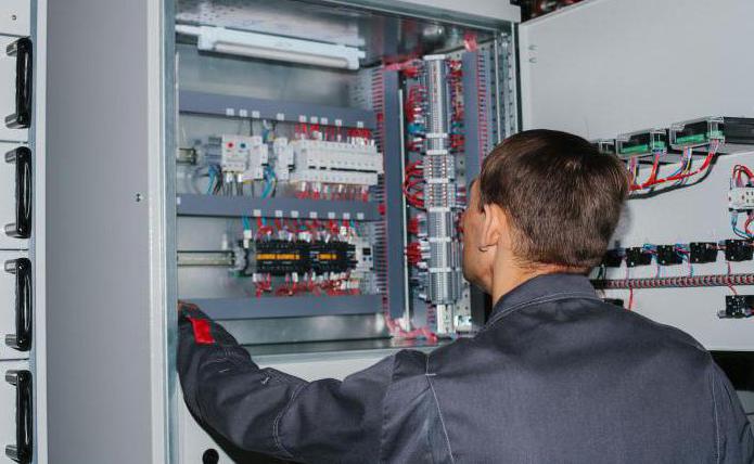
For crimping, special ferrules for a specific wire diameter can be used. There is a second method - soldering. It takes longer, but is less reliable and is used in low-power circuits. The junction is soft. At first, the terminals will be tightened to the maximum, but after some time they will loosen due to the fact that the solder begins to “float”. Poor contact can result in a fire.
What not to do?
Often used in old buildings aluminum wires, and the new connection diagrams have copper conductors. Inexperienced electricians can twist two metals together, which over time can result in replacement of the wiring. This happens for a reason chemical reaction between two different substances: aluminum and copper.
An oxidation process occurs, the rate of which depends on the load in a given circuit. If such a connection is necessary, then installation can be done through insulated terminal blocks. However, after long time The bolts will have to be tightened; they will loosen. Twists are not recommended for use in the shield. It’s better to sign each machine; after a few years, you may forget about the purpose of the device.
You can reduce the load on the machine by using energy-efficient household appliances and lighting lamps. This approach will allow you not to think about the possibility of insulation melting. The only risk remaining is a short circuit.
In case of malfunction
If the machine is knocked out, it is not recommended to turn it on immediately. First you need to evaluate possible reason faults: a recently hung shelf, a new appliance purchased, or no previous events. Overload could occur due to burnout of part of the wire in monolithic structures. For search problem area There are devices available to specialist electricians. This is relevant when the cost of opening the wall is much higher than the cost of diagnosing the electrical equipment of the house.
When the machine knocks out, it is recommended to use an ohmmeter and check if there is a short circuit to the ground or between the conductors: phase and neutral. Before this everything is turned off Appliances. Connection to the circuit is carried out one device at a time, while measuring the current through the wire using electric clamps.
Exceeding the load of the machine's rating requires either replacing the switch itself or changing its connection location. When diagnosing, you can check the wire with your hands without measuring instrument, taking care of the insulation during operation of consumers. If it heats up, then an increased current flows in the circuit.