Electricity is an indispensable attribute modern life. It is already difficult to imagine a house without any household appliances that provide comfort and make household chores easier for the housewife. But at the same time large number powerful consumers has a negative impact on electrical wiring. Minor malfunctions often occur, for example, a socket, switch, or other breakdowns began to spark. It’s expensive to call a qualified electrician every time, and most of these breakdowns can be easily fixed on your own. For correct connection household appliances and additional security When working with electrical wiring, you need to determine not only the phase, but also zero. Most often, a voltage probe in the form of a screwdriver is used for this. Today we’ll talk about how to use an indicator screwdriver.
Indicator screwdriver - operating principle and types.
Today, a large number of voltage indicators are produced in the form of a regular screwdriver. They all have general principle work, but may differ in design and form of execution. Conventionally, such indicators are divided into three groups. Let's look at them in more detail.
Simple indicator screwdriver
The design of a conventional probe in the form of a screwdriver is quite simple:
The sting acts as a conductor;
A thyristor is connected to it, reducing the current strength to a value safe for humans;
Then there is an LED, which is connected to a contact element located at the end of the screwdriver;
The body is made of transparent plastic, which allows you to see when the LED lights up.
The simplest and cheapest voltage probe has this design, which allows you to determine only the operating phase. Zero can be found with this screwdriver by elimination. In order to find the phase in the wires using indicator screwdriver, you need to do the following:
The tip of the screwdriver touches in turn all the wires of the contact group: socket, switch or break in the wiring. In this case, you need to touch the contact plate, which is located on the body, with your finger (it’s more convenient with your thumb);
When you touch a phase, the indicator will start to glow, but the diode will not glow at zero.
In this simple way, the indicator shows where the phase or neutral is in the wires or socket. After this you can make the connection correctly household appliance, for which it is important to maintain polarity.
Pay attention! Such work is carried out with the machine switched on on the panel. If it is necessary to determine the phase at the ends of the wires, they must first be stripped and moved apart so as not to cause a short circuit.
Indicator screwdriver with battery
Operating principle appearance and the device of such a voltage probe is no different from the screwdriver described above. The difference is the presence of two or three button batteries hidden in the handle. This device is more versatile and allows you to perform the following actions:
Find phase and zero in live wires;
Determine open circuit in de-energized circuit. To do this, you need to touch one end of the wire with your hand, and the other with the probe of a screwdriver. If the circuit is not broken, the indicator will light up. If there is a break in the wiring, the voltage indicator will not show anything;
In addition, such a tool, due to the above magnetic field shows the location of hidden wiring. To do this, the screwdriver is grasped by the tip with your fingers, and the handle is guided along the wall. When energized wiring is detected, the LED will light up.
Advice. This feature of this device very useful when you need to check the wall and determine the location of the wiring before drilling a hole.
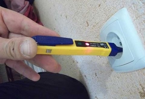
Universal indicator screwdriver
Such a device is called a screwdriver more out of habit; rather, it is a mini-tester. The tool runs on batteries, and the appearance is very different from previous options. On the front panel of the device there are two LEDs (red and green); depending on the model, there may also be a small display on which the measured voltage is displayed.
The indicator has a button for selecting the measurement mode. Let's consider the principle and purpose different modes:
Mode O is used to find the phase by contact method. If there is voltage on the conductor, the red LED lights up;
In mode L, the device operates at reduced sensitivity. This mode allows you to contactlessly determine the presence of voltage in hidden wiring depth up to 1.5 cm. When an electromagnetic field is detected, the green LED lights up and a buzzer sounds;
The H position indicates high sensitivity mode. This mode allows you to find phase and zero (of connected wiring) at a depth of up to 3 cm.
This device also allows you to test the circuit for open circuit, measure resistance up to 100 MOhm, you can determine the polarity, and measure the source voltage DC up to 36 V. This device is useful as a home tester: it allows you to check the performance of a lamp or other electrical appliance with a closed circuit. You can check any heating device, for example, a heater or a fireplace in case of a breakdown on the body.
two phases
Having figured out how to use an indicator screwdriver, I would like to talk about an interesting malfunction in the electrical network. It happens that when testing, for example, a socket, the probe determines the phase on both wires. In this case, do not be alarmed, nothing terrible happened. Most likely, the zero simply disappeared, and the phase moved on in the closed circuit, which is why the tester detects it on both wires. Let's look at the likely places where the zero could disappear and the reasons why this happened:
1. The most common place for a neutral wire to break is the driveway panel. It is almost always in the public domain, and there are a lot of wires wound there. Therefore, first of all, you need to check your terminal on the panel, disassemble it, clean the connection point and re-tighten the zero;
2. The second common reason is a broken machine or a plug on the meter in the apartment itself. The reason for this could be increased overload. It is worth noting precisely because this leads to the appearance of a phase on both wires, according to new PUE requirements installation of an automatic circuit breaker on the neutral wire is prohibited;
3. Zero is often “lost” in distribution box located in the room. The reason is weak contact and increased load;
4. In private homes, the cable can be damaged by mice. Moreover, it is still unclear why rodents are attracted to isolation, but the fact remains. Therefore, it is not recommended to lay in cottages open wiring, especially in the attic and under the floor. All wires must be laid in grooves or additionally protected;
5. Drilling into walls is one of the factors that can lead to wire breakage. That's why professional electricians Before such work, it is always recommended to check the drilling location using a hidden wiring indicator.
let's sum it up
In conclusion, we note that the sampler should be in any home. This can be as simple as an indicator screwdriver or an expensive electronic version: everyone chooses according to their capabilities and needs. There is no difficulty in using them: when correct operation the possibility of electric shock is completely excluded.
Sooner or later, problems and malfunctions arise in any electrical system. Experts recommend that if you have any electrical difficulties, seek help from experienced craftsmen, however, in practice, some problems can be solved independently, without wasting money and time on the services of a specialist.
Many network problems, subject to safety precautions, can be eliminated by a person on their own, for example, by replacing a socket, switch, or carrying out other simple tasks. renovation work. At the same time, troubleshooting in the network requires special tools– indicator screwdrivers.
Types of indicator screwdrivers
When problems occur in the network, people are interested in how to use this tool, but first they need to understand what types of indicators are on the market and which one is best in terms of price and functionality for home use.
Household indicator
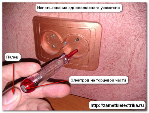
The most common and cheapest are household, single-task indicator screwdrivers, which are suitable for detecting phase wires. The device handles are made of transparent plastic. Inside the handle there is a neon light that lights up when there is a phase on the conductor being tested. Using an indicator screwdriver is very simple; to do this, you need to simultaneously touch its tip to the wire or contact, and your finger to the metal element at the end of the handle. Thus, the current will pass through the resistor inside the indicator to the first contact of the device's light bulb. The second contact of the light bulb is closed to the person through metal element, that is, during electrical measurements, the human body enters the working circuit of the indicator screwdriver, therefore, if you do not touch the metal contact, the light in the indicator will not light up.

This is the simplest device that should be in the arsenal of any home handyman. Such indicator screwdrivers are very cheap and can be found in any hardware store. It should also be noted that such a widespread and simple tool there is a serious drawback - the indicator screwdriver can only operate at a voltage of at least 60 V.
Indicator screwdrivers with LEDs are considered much more functional. In its design, such an indicator is in many ways similar to the tool described above, but there are significant differences between them. LED indicators are equipped with autonomous sources power supply - batteries, can operate at voltages below 60 V and have transistors.

The design features of such tools make it possible to use them not only to determine the phase conductor in electrical cables, but also to check the integrity of various electrical circuits– in wires and electrical appliances. Because of these features, LED indicator screwdrivers are considered multifunctional, although they are not much more expensive than the simplest indicators and their price is about $1.
Electronic indicator screwdrivers are the most functional and reliable devices, equipped with a convenient LCD display and sound alarm, informing the user about the presence of voltage. Such devices are multifunctional and easy to use; with their help, you can easily determine the presence of voltage and its magnitude, check AC and DC circuits in household electrical appliances, determine the polarity of networks, and also test the electrical circuit using light or sound indication.

Electronic indicators are considered the best household electrical measuring devices on the market. There are many such tools positive qualities and only one drawback - a quickly discharging battery.
As already mentioned, a modern electronic indicator is multifunctional device, with which you can carry out various electrical measurements at home. Most often, such a device is used to determine the phase wire in a socket; to do this, you need to turn off the power to the network and touch the tip of a screwdriver to the wire. If there is a phase, the electronic meter will indicate this with a sound signal and display the research results on the display.
An electronic indicator screwdriver can also be used to determine the location of current leakage - to look for a breakdown on the body of an electrical device. The measurement technique in this case is quite simple. The user will need to first bring the tip of the electronic meter to the ground wire in the outlet. Trigger sound signal or a light indicator indicates the presence of a breakdown. To determine the exact device of current leakage, it is necessary to disconnect all electrical appliances from the network, connect them in series and, after each connection, carry out re-measurement screwdriver When the indicator is triggered, we can say with confidence that the leak occurs when the device is turned on.
Modern electronic indicator screwdrivers also allow you to quite effectively search for a break point. electric cable. To conduct such studies you will need a diagram electrical wiring in a house or apartment. The switched on indicator will need to be moved slowly along the wall along the route of the electrical cable from the distribution boxes to the sockets. At the point where the cable is broken, the indicator light will stop lighting.
Safety precautions when using indicator screwdrivers
Modern indicators are functional and easy-to-use devices that allow owners and residents to save time and money when working with the electrical system. Despite the fact that each user can perform simple repair work on the electrical network independently, it is important to remember that the electrical system can pose a serious threat to the health and lives of people. To avoid putting yourself in danger, when working with indicator screwdrivers It is important to follow safety precautions:
- When measuring electrical system You only need to hold on to the insulated elements of the indicator screwdriver, excluding cases of checking non-live circuits.
- Before using the indicator, you must check it for functionality in an electrical circuit that definitely has phase voltage.
- Before using the indicator, you should read the instructions for its use. The instructions usually contain very useful and important information, for example, the power limits of the indicator. You can use only those devices whose power limits are not lower than the rated values in the electrical system under study.
- If you need to turn off the power for measurements electrical network, be sure to check that there is no voltage in the system before connecting the indicator screwdriver.
You've probably seen a voltage indicator in the shape of a pen more than once. It is convenient to carry it in the breast pocket of a shirt or overalls. Some modern models Such indicators can detect voltage even without metal contact with a live conductor. This species electrical protective equipment and this is what our article is dedicated to.
Terminology
In numerous articles posted on the Internet, you can find the terms “voltage indicator”, “indicator low voltage", "voltage indicator". However, often no distinction is made between the areas of their use, and sometimes they are even identified. Let's try to understand this issue.
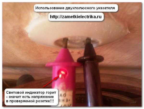
Numerous rules for the use of electrical protective equipment, which are constantly changing and republished, always use the term “voltage indicator”. In this case, all such devices are divided into bipolar ones, consisting of two bodies connected by a flexible insulated conductor; and single-pole, containing one body. The first ones work for active current, flowing through both housings, and the second - on capacitive flowing through the user's body.
The widely used term “voltage indicator” refers specifically to the second type of indicator. Their early models were produced in the form of a screwdriver with a light indicator in the handle. Modern devices more like a construction marker (though with a metal contact part at the end).
A few words about the containers around us
How does a capacitive voltage indicator work? To understand this, let's go back for a moment to electrical theory circuits and remember how a capacitor functions. It has two conductors, or plates, separated by a dielectric. Many people think that capacitors are separate elements electronic circuits, but in reality the world is filled with capacitors whose presence we usually simply do not notice. Here's an example. Suppose you are standing on a carpet covering a concrete floor directly under a 220-volt light fixture. Although you may not feel it, your body is conducting very little (on the order of a microampere) alternating current because it is part of a circuit consisting of two series connected capacitors. The two plates of the first capacitor are the filament in the light bulb and your body. The dielectric is the air (and maybe your hat) between them. The plates of the second capacitor are your body and the concrete floor (it is a fairly good conductor).
The dielectric of the second capacitor is the carpet plus your shoes and socks. Since the concrete floor is well grounded, so is neutral wire supply network, a voltage of 220 V is applied to the circuit of these two series capacitors. 
Where is the voltage indicator?
Understanding how grid voltage is divided between two series capacitors, is critical to figuring out how a capacitive indicator works.
Let's return to the theory of electrical circuits. IN series circuit the voltage will be distributed according to the resistance value (Ohm's law). For a capacitor, the smaller its capacitance, the greater the so-called capacitive resistance to alternating current. Thus, when two capacitors are connected in series, the largest proportion of the voltage applied to them will be dropped across the smaller device.
In the example above, only a few volts are between your feet and the floor (at the larger capacitance), and the rest of the 220V is applied between your head and the light bulb filament (at the smaller capacitance). Now if you keep thumb on the contact pad at the end of the handle of the capacitive indicator and touch it to the bare section of the wire powering the lamp, then instead of a small capacitance, a voltage indicator circuit sensitive to low currents is included in the capacitive current flow circuit. This current, of course, increases, but a high-resistance resistor inside the indicator limits it to a non-hazardous value. As a result of the flow of current, a neon lamp or LED lights up in the indicator or a buzzer sounds.
Traditional capacitive indicator
Mains voltage indicators in the form of a screwdriver, showing which pin of the electrical outlet is in phase and which is zero, appeared back in the 60s of the last century. Their electrical circuit includes a series-connected metal probe-tip, a high-resistance resistor in the resistance range from 0.47 to 1 MOhm with a small intrinsic capacitance between its terminals (for example, type MLT-1.0, VS-0.5, MLT-2.0 ), a neon light and a contact pad at the end of the handle. When the tip of a screwdriver touches the “phase” conductor and the capacitive current circuit is closed through the contact pad and the user’s body, the neon lamp lights up, which is a sign of voltage in the operating range of the indicator from 90 to 380 V (sometimes from 70 to 1000 V) at a current frequency of 50 Hz .
Why neon light bulb?
Can it be replaced with another indicator? For a long time it was thought not. Indeed, with capacity human body of the order of hundreds of pF and a voltage of U = 220 V, the maximum capacitive current with a frequency of f = 50 Hz through it to ground is U/(1/ωC) = U2πfC = 220 x 6.28 x 50 x n100 pF = n7 μA. And for an LED to light up, a current of the order of milliamps must pass through it. However, special circuit solutions were found that made it possible to create a voltage indicator using LEDs, piezoceramic buzzers and other display elements.

From neon to LED
The solution was to change the glow mode itself from continuous to pulsed. If you try to estimate the power consumed by a neon lamp, then at a voltage of 100 V and a capacitive current of 20 μA, it will be 100 x 20 μA = 2 mW. If you supply such power to the LED over a time interval, for example, 10 ms, and not a whole second, then it will light up quite well during this interval. After all, at a voltage of 100 V, the current through it will be 0.002 W x 100/100 V = 0.002 A = 2 mA.
If you ensure the accumulation of energy in some circuit (for example, in a relaxation generator) for a fraction of a second, and then sharply release it to the LED in 10 ms, then the latter will periodically flash brightly. It will work out LED indicator voltage without built-in battery.

Which way did they go in China?
Chinese developers decided that since an LED requires a constant current of the order of several milliamps to glow continuously, they need to build a AA battery (or two) into the indicator. In this case, the current through the LED opens the simplest transistor switch, driven by capacitive current through the user's body.
Has the scheme been simplified? In general, yes, but she became extremely sensitive to various kinds tips. Therefore, the reliability of the readings of such indicators is questionable.

Digital voltage indicator
The glow of a neon light bulb or LED, of course, reliable way indication of the presence of voltage, but it is too uninformative if the circuit has several voltage levels. In this case, measuring electronics, which has rapidly developed in recent decades, comes to the rescue.
The most in a simple way To make the indicator more informative is to introduce several voltage comparators into its circuit, which operate at different voltage levels. The output of each comparator controls its own indication element on the device body.

A real digital voltage indicator is obtained if the measured voltage is digitized on the built-in ADC, and then through a special circuit is supplied to seven-segment display elements capable of displaying numbers from 0 to 9, or to a small-sized matrix digital indicator. Expensive professional voltage indicators are built using this scheme.
You need to be on top of things with electricity!!! (time-tested wisdom).
Many have probably heard that a real electrician is not one who is not afraid of electricity, but one who is able to avoid direct contact with electricity. According to statistics, from defeat electric shock, electricians with ten or more years of experience most often die. It is at this age that the sense of danger becomes dull. Some experienced electricians check the presence of electricity by touch, yes, by touch. But why risk your own life when there are instruments that indicate the presence of voltage?
There are quite a lot of devices that indicate the presence of voltage - from the simplest voltage indicator on a gas-discharge light bulb (neon) to devices that show not only the presence of voltage but also many other parameters.
In this article we will look at indicators and voltage indicators, which are most often used in their practice by both professional electricians and home craftsmen. In electrical installations, indicators with signal lamps are most often used.
Relatively recently, we have had voltage indicators that allow us to detect the presence of voltage without direct contact with a live conductor.
 Example of this type The devices are equipped with a Chinese-made indicator (even though it says everywhere that it was made in Germany) - MS-18, MS-58, etc.
Such indicators consist of an LED, two miniature batteries and a pair of radio components. Such indicators can be used safely if you have enough experience and knowledge in electricity, since these indicators react to everything. For novice electricians and people without experience, using these probes is undesirable and even dangerous.
Two-pole voltage indicator consists of a neon lamp, additional resistance and contacts 1. Neon lamp, so that there is no glow under the influence of capacitive current. The indicator elements are fixed in two plastic housings 2, connected flexible wire 3 1 m long with increased reliability insulation.
Bipolar indicators require touching two points of the electrical installation, between which it is necessary to determine the presence or absence of voltage.
There are quite a lot of varieties of such indicators. They also differ in functionality.
The simplest indicators only show the presence of voltage. An example of such an indicator is the PIN-90 series devices (-2m, -2mu), UN500, -453, UNNU-1, UNN-10, MIN-1, etc. More advanced models - the ELIN-1 series (-SZ, -S3 IPM, -S3 Combi) and many other devices show not only the presence of voltage in the test section of the circuit, but also its nominal value and voltage polarity.
The following indicators are used: neon lights, LEDs various colors, digital and indicators. There are also combined indicators, where along with light indication there is also sound, which makes working with devices more comfortable and safe.
Unlike single-pole pointers and indicators, in order to find out about the presence of voltage with these (double-pole) devices, it is necessary to use two probes. The use of such devices gives a more complete picture of the presence or absence of voltage, which is undoubtedly very important in the work of electricians.
In addition to checking for the presence or absence of voltage in the section of the circuit being tested, some bipolar indicators can be used as a “continuity test”, that is, to check the circuit for an open circuit.
 Digital devices are also quite popular among electricians. These universal devices allow you to check voltage, resistance, etc. The display uses a digital display, sound and light indication.
Some models are equipped without disturbing the conductor insulation. Also, many tester models are equipped with a temperature sensor, with which you can measure the temperature of equipment - transformers, motors, power switches.
Cautions:
1. It is not permitted to use a test lamp (a regular socket with two terminals) as a voltage indicator in networks with a line voltage greater than 220 V, since if it is switched on by mistake, line voltage in a 380/220 V network, the lamp explodes and fragments can injure the worker.
2. In practice, single-pole voltage indicators are often made on their own, usually in the form of a screwdriver. In this case, there are cases of improper manufacturing, and then there is a danger of electric shock. You cannot make the screwdriver shaft longer than 20 mm. If the rod is long, there is a danger of touching it when checking the voltage. It is advisable to tightly pull the insulating tube onto the rod, leaving an uninsulated section of no more than 5 mm in length. On the side close to the voltage source, there must be a thrust ring protruding 3-4 mm to prevent the hand from slipping.
Particular attention should be paid to the selection of a neon bulb so that the ignition threshold does not exceed 90 V. The IN-3 type lamp is most suitable. The additional resistance must be at least 200 kOhm.
The housing should be made of hard rubber or plastic of a dark color, in which it is easier to notice the glow of the light bulb. Manufactured signs must be tested.
In any case, using indicators and voltage indicators, knowledge and skills are required when working with them. Also, do not forget about safety precautions. And, trust the professionals, electricity, as you know, does not forgive jokes and mistakes!
Used during operation and repair of electrical installations.
Today's article will focus on low voltage indicators.
Low voltage indicators (LNV) are used to check the presence or absence of voltage in electrical installations up to 1000 (V) on those live parts where work will be performed. UNN is also used to check phase coincidence, i.e. low voltage phasing.
Low voltage indicators, or otherwise called voltage indicators up to 1000 (V), are of 2 types:
- single pole
- bipolar
Therefore, the application will depend on what kind of pointer you use.
There are a large number of varieties of low voltage indicators from different manufacturers.
I will not dwell on each type, but will only talk about the most common and reliable low-voltage indicators that I personally use.
For example, a single-pole low voltage indicator in the form of an indicator screwdriver is used in electrical installations only AC voltage from 100 (V) to 500 (V) and frequency 50 (Hz). The principle of operation of such a pointer is based on the flow of capacitive current.
The two-pole low voltage indicator (UNN-10K) has more wide application. It can be used in electrical installations, both alternating current with voltage from 110 (V) to 500 (V) and frequency 50 (Hz), and direct current with voltage from 110 (V) to 500 (V).

Its operating principle is based on the glow of a gas-discharge lamp when active current flows through it.
I use the two-pole low voltage indicator (PIN-90M) just as often. Its operating principle and design are similar to UNN-10K.

The difference lies only in the limits of the controlled voltage. Its operating voltage ranges from 50 (V) to 1000 (V).
- testing the insulation of handles and wires
- trial increased voltage
- indication voltage determination
- measurement of the current passing through the VNA at the highest operating voltage
1. Testing the insulation of handles and wires of low voltage indicators
Testing the insulation of housing handles and wires of low voltage indicators is carried out once a year according to the following principle:

Both housings (handles) of the two-pole low voltage indicator are wrapped in foil. The connecting wire is lowered into a bath of water, where the water temperature should be in the range of 10 - 40 ° C. It is necessary to maintain a distance of 0.8 - 1.2 (cm) between the water and the indicator housings.
We connect the first lead from the test transformer to the electrode tips. The second (grounded) terminal must be lowered into a bath of water and connected to the foil.
Similarly, the insulation of the housing (handle) is tested for single-pole low voltage indicators. The body is wrapped in foil along its entire length. It is necessary to maintain a distance of 1 (cm) between the foil and the electrode located at the end of the pointer. We connect one lead from the testing device to the tip electrode. The other (grounded) terminal goes to the foil.
For UNN with operating voltage up to 500 (V), a test voltage of 1000 (V) is applied for 1 minute.
For UNN with operating voltage up to 1000 (V), a test voltage of 2000 (V) is applied for 1 minute.
2. Testing low voltage indicators with increased voltage
Testing low voltage indicators with increased voltage is carried out as follows.
A test voltage of 1.1 times the highest operating voltage UNN is applied between the electrode tips for bipolar indicators, or between the electrode tip and the end part for single-pole indicators for 1 minute.
3. Determination of indication voltage
The voltage from the testing device is gradually increased, while fixing the voltage indicator indication voltage (VIN).
Low voltage indicators must have an indication voltage of no more than 50 (V).
4. Measurement of the current passing through the UNN at the highest operating voltage
The voltage from the testing device is gradually increased to the highest operating voltage of 1000 (V), while the magnitude of the current flowing through the UNN is recorded.
For bipolar voltage indicators, the current value should not exceed 10 (mA).
For single-pole voltage indicators, the current value should not exceed 0.6 (mA).
How to use a voltage indicator?
Before applying and using the low voltage indicator, you must ensure that it is in good condition, by touching live parts of an electrical installation that are known to be energized. It is also necessary to check the presence of a stamp confirming the testing of UNN.
Checking the absence of voltage with a low voltage indicator is carried out on live parts by direct contact. The contact time must be at least 5 seconds.

When using a single-pole low voltage indicator, the use is not permissible, because it is necessary to ensure contact between the electrode on the end of the body and the person’s finger.

P.S. This concludes the article on the topic of low voltage indicator. If you have any questions while studying the material in the article, please ask them in the comments. Don't forget to subscribe to new articles from the site. News about the release of a new article will be sent directly to your inbox.