Checking electronic components using multimeter this is a pretty simple task. To do this, you need an ordinary Chinese-made multimeter, the purchase of which is not a problem, it is only important to avoid the cheapest, frankly low-quality models.
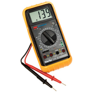
Analogue meters with a pointer indicator are still capable of performing such tasks, but are more convenient to use digital multimeters , in which the mode is selected using switches, and the measurement results are displayed on an electronic display.
Appearance of analog and digital multimeters:
Nowadays, digital multimeters are most often used, since they have a lower percentage of error, are easier to use, and the data is displayed directly on the device’s display.
The scale of digital multimeters is larger, there are convenient additional functions - temperature sensor, frequency meter, capacitor test, etc.
Transistor check
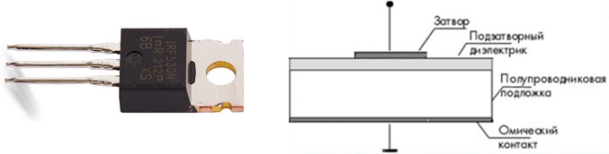
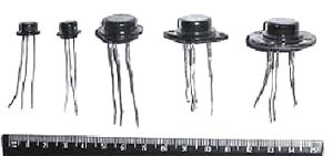
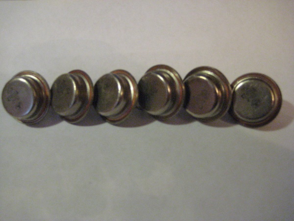
Without going into technical details, transistors can be field-effect and bipolar

A bipolar transistor consists of two counter diodes, so the test is performed according to the “base-emitter” and “base-collector” principle. The current can only flow in one direction, it should not be in the other. There is no need to check the emitter-collector junction. If there is no voltage at the base, but current still flows, the device is faulty.
To check the field effect transistor N-channel type, you need to attach the black (negative) probe to the drain terminal. A red (positive) probe is connected to the source terminal of the transistor. In this case, the transistor is closed, the multimeter displays a voltage drop of approximately 450 mV on the internal diode, and infinite resistance on the reverse. Now you need to attach the red probe to the gate, and then return it to the source terminal. The black probe remains attached to the drain terminal. Having shown 280 mV on the multimeter, the transistor opened when touched. Without disconnecting the red probe, touch the black probe to the shutter. The field-effect transistor will close, and we will see a voltage drop on the multimeter display. The transistor is working properly, as these manipulations showed. Diagnostics of the P-channel transistor is performed in the same way, but the probes are swapped.
Diode check
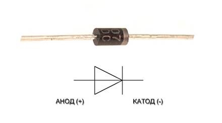
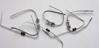
Several main types of diodes are now produced (zener diode, varicap, thyristor, triac, light and photo diodes), each of them is used for specific purposes. To check the diode, the resistance is measured with a plus at the anode (should be from several tens to several hundred Ohms), then with a plus at the cathode - it should be infinity. If the indicators are different, the device is faulty.
Checking resistors
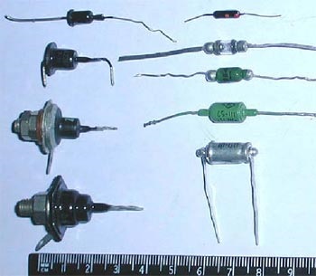
As you can understand from the picture, resistors are also different:

Manufacturers indicate the nominal resistance on all resistors. We measure it. A 5% error in the resistance value is allowed; if the error is greater, it is better not to use the device. If the resistor has turned black, it is also better not to use it, even if the resistance is within normal limits.
Checking capacitors
First we inspect the capacitor. If there are no cracks or swelling on it, you need to try (carefully!) Twist the capacitor leads. If you can turn it or even pull it out altogether, the capacitor is broken. If everything looks normal, we check the resistance with a multimeter; the readings should be equal to infinity.
Inductor
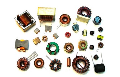
Failures in coils can be different. Therefore, we first rule out a mechanical fault. If there is no external damage, we measure the resistance by connecting the multimeter to the parallel terminals. It should be close to zero. If the nominal value is exceeded, there may be a breakdown inside the coil. You can try to rewind the coil, but it’s easier to change it.
Chip
There is no point in checking a microcircuit with a multimeter - they contain dozens and hundreds of transistors, resistors and diodes. The microcircuit must be free of mechanical damage, rust stains and overheating. If everything is fine externally, the microcircuit is most likely damaged internally and cannot be repaired. However, you can check the outputs of the microcircuit for voltage. Too low resistance of the power outputs (relative to the common) indicates a short circuit. If at least one of the outputs is faulty, most likely the circuit cannot be returned to operation.
Working with a digital multimeter
Like an analog tester, a digital tester has red and black probes, as well as 2-4 additional sockets. Traditionally, the "ground" or common terminal is marked black. The common output socket is indicated by a “-” (minus) sign or the COM code. The end of the output is sometimes equipped with an alligator clip for fastening to the circuit being tested.
The red lead always uses a socket marked "+" (plus) or code V. More complex multimeters have an additional socket for the red lead, labeled "VQmA". Its use allows you to measure resistance and voltage in milliamps.
The socket marked 10ADC is intended for measuring direct current, up to 10A.
The main mode switch, which has a round shape and is located in the middle of the front panel in most multimeters, serves to select measurement modes. When choosing a voltage, you should choose a mode greater than the current strength. If you need to check a household outlet, from two modes, 200 and 750 V, select mode 750.
This article will talk about how to check the functionality of a microcircuit using a conventional multimeter. Sometimes determining the cause of a malfunction is quite simple, but sometimes it takes a lot of time, and as a result the breakdown remains unclear. In this case, you need to replace the part.
Three options
Checking microcircuits is a rather complex process, which often turns out to be impossible. The reason lies in the fact that the chip contains large number various radioelements. However, even in this situation there are several ways to check:
- external inspection. By carefully examining each element of the microcircuit, you can detect a defect (cracks in the case, burnt contacts, etc.);
- . Sometimes the problem lies in a short circuit on the part of the power supply; replacing it can help correct the situation;
- performance check. Most microcircuits have not one, but several outputs, so a malfunction of at least one of the elements leads to failure of the entire microcircuit.
The easiest to check are the KR142 series microcircuits. They have only three pins, so when any voltage level is applied to the input, a multimeter checks its level at the output and draws a conclusion about the state of the microcircuit.
The next most difficult tests are the K155, K176, etc. series microcircuits. To check, you need to use a block and a power source with a specific voltage level selected for the microcircuit. Just as in the case of KR142 series microcircuits, we apply a signal to the input and monitor its output level using a multimeter.
Using a special tester
For more complex checks, you need to use a special microcircuit tester, which you can purchase or make yourself. When dialing individual components of the microcircuit, data will be displayed on the display screen, analyzing which you can come to a conclusion about the serviceability or malfunction of the element. It is worth remembering that in order to fully test the microcircuit, you need to completely simulate its normal operating mode, that is, ensure the supply of voltage at the required level. To do this, the test should be carried out on a special test board.

Often, it turns out to be impossible to test a microcircuit without soldering the elements, and each of them must be called separately. How to ring individual elements of the microcircuit after desoldering will be discussed below.
Transistors (field-effect and bipolar)
We switch the multimeter to the “testing” mode, connect the red probe to the base of the transistor, and touch the collector terminal with the black one. The display should show the breakdown voltage value. A similar level will be shown when checking the circuit between the base and emitter. To do this, connect the red probe to the base, and apply the black probe to the emitter.
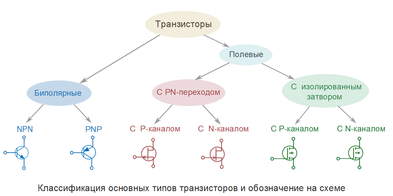
The next step is to check the same transistor terminals in reverse connection. We connect the black probe to the base, and with the red probe we touch the emitter and collector in turn. If the display shows one (infinite resistance), then the transistor is working. This is how field-effect transistors are tested. Bipolar transistors are checked using a similar method, only the red and black probes are swapped. Accordingly, the values on the multimeter will also show the opposite.
Capacitors, resistors and diodes
The serviceability of the capacitor is checked by connecting the probes of a multimeter to its terminals. Within a second, the resistance will increase from a few ohms to infinity. If you swap the probes, the effect will repeat.

To ensure that the resistor is working properly, it is enough to measure its resistance. If it is different from zero and less than infinity, then the resistor is working.
Checking diodes from a microcircuit is quite simple. By measuring the resistance between the anode and cathode in direct and reverse sequence (switching the multimeter probes), we make sure that in one case one is at the level of several tens to hundreds of Ohms, and in the other it tends to infinity (one in the “dialing” mode on the display ).
Inductance and thyristors
Checking the coil for a break is carried out by measuring its resistance with a multimeter. The element is considered serviceable if the resistance is less than infinity. It should be noted that not all multimeters are capable of testing inductance.
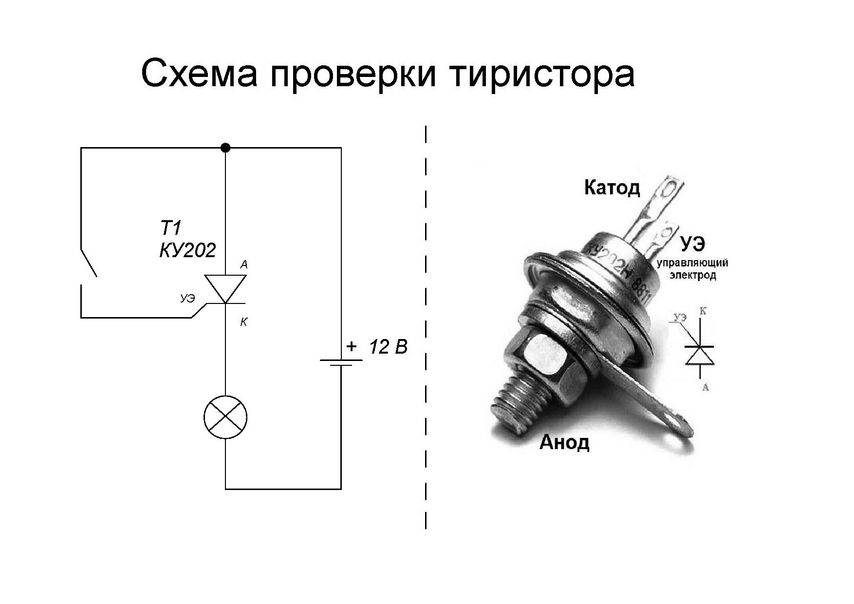
The thyristor is checked as follows. We apply the red probe to the anode, and the black probe to the cathode. The multimeter window should display infinite resistance. After this, we connect the control electrode to the anode, observing the drop in resistance on the multimeter display to hundreds of ohms. We disconnect the control electrode from the anode - the resistance of the thyristor should not change. This is how a fully functional thyristor behaves.
Zener diodes, cables/connectors
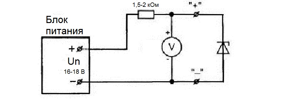
To test the zener diode you will need a power supply, a resistor and a multimeter. We connect the resistor to the anode of the zener diode, through the power supply we apply voltage to the resistor and the cathode of the zener diode, gradually raising it. On the display of a multimeter connected to the zener diode terminals, we can observe a smooth increase in the voltage level. At a certain point, the voltage stops increasing, regardless of whether we increase it with the power supply. Such a zener diode is considered serviceable.
To check the loops it is necessary. Each contact on one side must call a contact on the other side in the “dialing” mode. If the same contact rings with several at once, there is a short circuit in the cable/connector. If it doesn’t ring with any of them, it’s a break.
Sometimes faulty elements can be determined visually. To do this, you will have to carefully examine the microcircuit under a magnifying glass. The presence of cracks, darkening, or broken contacts may indicate a breakdown.
Unfortunately, sooner or later any technology begins to work incorrectly or stops functioning altogether. Often this happens due to the failure of the microcircuit, or more precisely, due to the breakdown of certain parts on the microcircuit. The most important and at the same time the least reliable elements There are capacitors in the circuit.
 Capacitors are devices capable of storing electric charge. The design of this part is quite simple and consists of two conductive plates, between which the dielectric is located. Most important characteristic of this element is its capacity. Its value depends on the thickness of the conductive plates and dielectric. The unit of measurement for device capacitance is called Farad. IN electrical circuit the capacitor is a passive element since it does not affect the conversion electrical energy. It is also capable of providing what is called AC reactance.
Types of capacitors
Based on their operating principle, they are divided into two types:
- polar;
- non-polar.
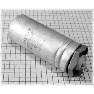 Electric capacitors that use an electrolyte are polar. Thanks to the electrolyte located inside, instead of one of the conductive plates, polarity is achieved. Polar capacitors have a separate contact terminal for plus and minus. If included in electrical diagram such a part, without taking into account the polarity, it will quickly fail. The capacity of electrolytic type elements starts from 1 microFarad and can reach hundreds of thousands of microFarads.
Capacitors with a small capacitance are called non-polar. In such devices no electrolyte present, accordingly, they can be included in the circuit as desired.
Functionality check
 In order to check a specific element on a microcircuit and obtain reliable information about its condition, it should be removed from the microcircuit. If the part is not soldered, then the elements located on the board next to the one we need will distort the readings obtained at the time of measuring its capacity.
After the capacitor being measured is soldered out of the circuit, it must be visually checked for the presence of any defects. If any are detected, such a part automatically becomes unusable.
If a visual check does not reveal any damage, then you should start checking the elements of the microcircuit with a multimeter.
Multimeter
 This is a device that makes it possible to measure constant and AC, power and resistance levels electrical networks, as well as accurately set the internal capacitance of the capacitors.
Before you start checking any elements with a multimeter, you need to check the serviceability of the multimeter itself. For this The device regulator must be set to the ringing position, after which the probes of the multimeter are pressed against each other and if it starts to squeak, then it means it is working.
Next, you can check all elements for serviceability. A great way would be to check the capacitor to see if it can charge. To do this, you need to take an electrolytic type part and set the tester using the regulator to the continuity position. Next, the multimeter probes must be installed on the part according to the polarity symbols, plus to plus, minus to minus. If the part is in good condition, the multimeter display will display numerical values that gradually increase to infinity. After the element being measured is finally charged, the tester will emit beep, and the display will begin to display a unit, which also indicates the correct operation of the part being tested.
 It’s also very easy to figure out how to test capacitors for resistance with a multimeter. First the tester must be set to the resistance measurement position, after which, as in the case of measuring capacitance, when the probes touch the part, the value of the nominal resistance will be displayed on the digital display or multimeter scale.
But it often happens that when checking with a multimeter, the part becomes faulty. There are only two main reasons why a previously working element stops functioning:
- breakdown;
- break.
The breakdown occurs as a result of the so-called drying out of the capacitor. Over time, the dielectric between the conductive plates is destroyed, gradually losing its properties. As a result, current passes between the plates, which leads to a short circuit and combustion of the part. If you check a broken capacitor with a multimeter, then touching it with the probes, the tester will start beeping, and the display will display zero, which indicates that there is no charge in the device.
At the moment of such a malfunction as a break during measurement, the device, instead of a smooth increase in resistance indicators, instantly will give the maximum value of the capacitor charge, which also indicates its malfunction and such element should be immediately replaced with the same or similar one.
Very often we encounter this problem: due to a small breakdown radio components The whole unit fails. To somehow make your life easier, you need to be able to quickly check and fix breakdowns. To do this, we will now learn how to check correctly and, most importantly, quickly radio components. Regardless of the manufacturer, be it imported, domestic or Soviet radio components, the principles and testing methods are identical. Naturally, visually we will not always be able to understand whether this part is working or not, so we will need a multimeter.
Checking bipolar transistors.
The most common failure is burnt out circuits transistors. So let's start with them. To check their performance, first of all we “call” the BASE-EMITER and BASE-COLLECTOR transitions. It should be taken into account that the PNP transistor conducts current to the BASE, and the NPN transistor conducts current from the BASE (the current flows only in one direction, it should not flow in the opposite direction). Next, we call two EMITTER-COLLECTOR transitions. Bye transistor closed, no current should pass through them in any direction. As soon as voltage is applied to the BASE, the current passing through the BASE-EMITER junction opens transistor, at the same time, the resistance of the EMITTER-COLLECTOR junction drops sharply, almost to zero. It should be noted that the voltage drop across the junctions is usually not lower than 0.6V (for prefabricated Darlington transistors it is more than 1.2V, and therefore multimeters with a 1.5V battery will not be able to open them). I recommend purchasing a multimeter with a more powerful battery.
It should also be noted that in some modern transistors A diode is built in parallel with the COLLECTOR-EMITER circuit (check the documentation if the COLLECTOR-EMITER rings in one direction).
RESULT: if at least one of the statements is not confirmed, the transistor is faulty. Before replacing it, check the remaining parts.
We check unipolar transistors.
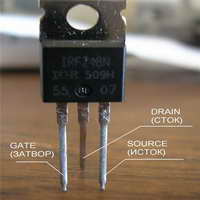
Resistance between all terminals unipolar (field-effect) transistor must be infinite. Regardless of the test voltage, the device should show infinite resistance. But there are some exceptions!!!
By applying a positive probe to the n-type gate and a negative probe to the source of the transistor, the gate capacitance will be charged and the transistor will open. The device will show some resistance between the drain and source. This is not a malfunction. Just before testing the drain-source channel, close all the legs transistor to discharge the gate capacitance. Only after this, if the drain-source resistance is not infinite, can the transistor be considered faulty.
It should be remembered that in powerful modern field effect transistors There is a diode between the drain and the source, so when checking the drain-source channel, the transistor will behave like a regular diode. Don’t forget to read the datasheets for your radio components.
Checking the capacitors.
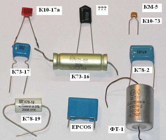
Some of the most damaged radio components are, and electrolytic ones break more often, ceramics and film - on the contrary.
Our initial actions are a visual inspection of the board. Electrolytic capacitors after failure they inflate and sometimes even explode. Ceramic capacitors They don't inflate, but they can explode. Just like electrolytic ones, they need to be ringed. They should not conduct current.
The next step we perform is a mechanical check of the internal contact pins. To do this, bend the leads of the capacitor under small angle, slightly pulling and turning them in different directions, we make sure that they are motionless. If at least one pin rotates around an axis or is freely removed from the housing, then it is unusable.
The last thing we do is measure the resistance. When connecting the probes, the resistance from units of Ohms will increase to infinity within a second. When changing the locations of the probes, the effect will repeat. This effect is most noticeable with capacitances greater than 10 µF.
Now we can conclude: if the capacitor conducts current or does not charge, it is faulty.
Checking the resistors.

Resistors- these are the most common on boards radio components. Resistors They do not fail as often as other components, and they are much easier to check.
The first step is a visual inspection. If resistor blackened(overheated), then it is most likely faulty, and even if it is working, I recommend replacing it.
Next - dialing. If the resistance is less than infinity and not zero, most likely resistor suitable for use. We measure the resistance, and if it differs from the nominal value by more than ±5%, such resistor better to replace.
Checking the diodes.
Well, everything is very simple here. We measure the resistance. With a plus on the anode it should show several tens or hundreds of Ohms, with a plus on the cathode - infinity. Otherwise diode faulty
Checking the inductance.
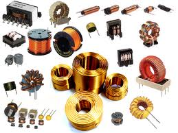
There are two reasons for inductance failure: the first is a short circuit of the turns, the second is a break.
We determine the break by measuring the resistance; it should be less than infinity.
A short circuit is more difficult to calculate. For chokes and transformers with windings of at least 1000 turns, we check the self-induction voltage. To do this, we apply a low-voltage pulse to the winding and then short-circuit this winding with a gas-discharge light bulb. The pulse must be applied by lightly touching the contacts of the battery. If the light eventually blinks, then short circuit No. Otherwise, there are either few turns or a short circuit.
Of course, this method is not entirely accurate, so before you “sin” on inductance, check the other details.
We check optocouplers.
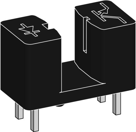
First we call the emitting diode. Like a regular diode, it should ring in one direction.
Then, having supplied power to the emitting diode, we measure the resistance of the photodetector (depending on the optocoupler, it can be a diode, transistor, thyristor or triac). The resistance should be close to zero. Then we remove the power; if the resistance increases to infinity, it means it’s working.
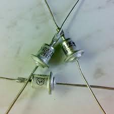
We check thyristors (triacs).
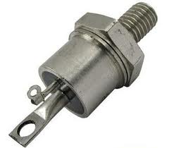
To check, take an ohmmeter. We connect plus to the anode, minus to the cathode. The resistance must be infinity. Then we connect the control electrode to the anode. The resistance should drop to about a hundred ohms. After this, disconnect the control electrode from the anode. The resistance should remain low (this is called holding current). Otherwise we reject it.
In future articles we will look at checking and discarding most of the remaining components.
Please note: if you find faulty radio components and want to replace them, we will be happy to help you find any radio parts and components.