Tester (multimeter) is a measuring tool needed for those whose hobby is electricity. In addition, it can often be useful in the home, because it allows you to identify damage in electronic devices, inspect the battery charge and measure the operating voltage of many electrical appliances. For a person encountering it for the first time, this is a real dark box. Don't give in to memories
from the somewhat intricate appearance of the tester (numbers, icons, pin terminals, etc.). It is enough to know just a little to make sure that this equipment is easy to use, and most importantly, that with its invaluable help you can detect breakdowns in electrical appliances (and solve the difficulties associated with them) from light bulbs to complex electrical household devices.
Types and design:
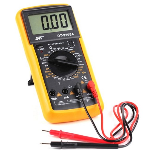
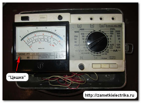
The two testers shown in the photo belong to two different types. On the left - “analog type”, in other words, they have a visible arrow in the window, which, deviating from the zero mark, shows the measured value on the scale. On the right is a tester, on the contrary, of a “digital type”: the measured value appears on the screen in the form of numbers. All testers have insulated probes connected to the device using plugs, the conductive part of which touches the measurement sites.  At first glance, the tester may seem like a complex and difficult-to-use tool. In reality, this is a successful and easy-to-use device. From different models, available for sale, it is better to purchase the most ordinary and cheap one. More complex instruments are designed to capture subtle measurements that are unlikely to intrigue a non-specialist. The measured values can be read from the dial indicator ( analog type) or specifically from the monitor (digital type). In the latter case, reading is obviously even simpler and faster. All testers are also equipped with two probes with insulated handles, which are connected to the device by two electrical wires using plugs to which the reverse ends of these wires are connected. Almost all models have a rotating toggle switch, with which you select the type of measurement to be performed. Using the toggle switch, you can select both the measured value (voltage, resistance, current) and the measurement spectrum for each of the measured features listed above.
  For a tester with a dial indicator, depending on the type of measurement, you need to read the value from the corresponding scale.
  It may be useful to measure quantities such as: voltage (variable or constant), electronic resistance and current (at variable or constant voltage).
Probable measurements: in the picture above: an image illustrating the measuring scale of an analog tester. A curve with plotted digital values is created to capture data when measuring different characteristics(voltage, resistance, current). By installing the rotating toggle switch in different positions, different measurement spectra can be obtained. Resistance is measured in the following spectra: ohms (Ohm), x10, x100 and x1000. In order to select one of these ranges, you need to properly install the toggle switch beak. The value indicated by the arrow should be multiplied by 10.100 or 1000, respectively. Voltage (variable and constant) is measured in volts (V). And in this case, different measurement spectra are installed on the tester (10,50,250,500 V). Current strength is indicated in amperes (A) and fractional units: milliamps (mA). All testers can measure constant current in amperes; only the best models can measure alternating current.
Voltage measurement: Measuring voltage allows you not only to find out its value, but also to simply find it, but, in fact, whether it exists or not. For example, using a tester you can find out whether there is voltage in the outlet or whether the battery is charged. In order to make a freeze, you need to select the parameter to be measured using the rotating toggle switch (select " AC voltage") for electrical appliances, or " constant pressure» for batteries, batteries, etc. and the range of measurements suitable for this measurement. When the probes touch elements between which there is voltage (contact holes of the socket, battery terminals, etc.). the arrow deviates from zero from the mark and shows on the scale the value corresponding to the voltage value. Well, if the tester is digital, a number appears on the screen indicating the voltage value in volts (or fractions of volts).
Resistance measurement: Measuring resistance is very important. when you need to check whether there is an open circuit in the electronic circuit. After all, the design of certain devices (iron, electronic lamp, etc.) is a specific electronic circuit that “begins” and “ends” with the plugs of the power plug, and if the device does not work, it may be useful to check if there is an open circuit in this circuit . When measuring resistance, first, as with other measurements, select the spectrum appropriately by setting the toggle switch on the tester. Then the probes touch the points between which you need to measure the resistance. If the resistance value shows “infinity”, this indicates an open circuit and the need for repair. When you set the toggle switch to the “dialer” mode, you can check by the sound signal whether the filament in the lamp has burned out, whether there is a break in the internal winding, or whether the wire has come loose from the contact in the socket. In addition, this technique makes it possible to find in the inductor coil, the terminals of each winding, or check whether the switch is working, and also check the serviceability of the fuse.
Warning: before you start measuring resistance, you should make sure that the circuit is de-energized!
Current measurement: Current measurement is a more “sophisticated” implementation of the tester. It must be created with care. Therefore, for greater safety, it is better to entrust this operation to a specialist; the fact is that a similar freeze is made in a circuit that is energized (in other words, when there is current in it), and requires special knowledge and technical abilities. In other words, we are talking about the “serial” inclusion of the tester in the circuit of the operating device; frozen is done when current passes through it and, accordingly, through the tester. Naturally, it is necessary to previously set the tester’s toggle switch to the appropriate type of measurement (amps for alternating current or milliamps for constant current).
Sequence of measurements: Use the toggle switch to select the type of measurement you need to make. The appropriate measurement spectrum is immediately set.
Measurement spectrum: This highest value scale, within the boundaries of which measurements are taken with an analog tester and can be changed to obtain more accurate measurements. If you are measuring 4 volts on a 1000 volt scale, the needle's deviation from zero danger will be so small that it will be practically impossible to take a reading. But if you use the toggle switch to select the smallest spectrum - 10 V, the needle will make a noticeable deviation from zero danger, which will allow even more clear readings. Thus, any value on the scale can be compared with the measurement spectrum. Insert the probe pins into the appropriate connectors so that the tester can be connected to the circuit in which you are going to take measurements. To check whether the light bulb has burned out, touch the threads and contact parts of its base with probes and measure the resistance. If the meter indicates an infinite value, it means the light bulb has burned out. The discharge of a battery is simply checked by measuring the voltage between its poles. If it is clearly below nominal, this indicates that it is discharged. Select a scale for measuring AC voltage (measurement range greater than 250 volts), connect the probes of the device to the outlet and make sure that the arrow points to 220 volts.
When working with high voltages, be careful not to touch the iron parts of the probes!
Setting the arrow to the zero mark: For a tester with an analog scale, the needle at rest may not perfectly coincide with the zero mark. You can set it to zero by turning the screw located under the scale, which adjusts the axis of rotation of the pointer. In order to check whether the tester is working correctly and whether the battery in it is dead, set the toggle switch to measure resistance and short-circuit the probes. The arrow should deviate towards the zero mark on the ohmic scale.
Battery for tester: Each tester contains a battery that produces current and is needed to measure resistance. It should be replaced from time to time: despite the fact that measuring resistance does not consume enough energy, over time the element loses charge. The tester is a narrow device that cannot be subjected to shock and should be protected from water getting into it.
How to use a multimeter? This question is often asked on the forum, which is why this laconic guide was written. For example, we took the most common and cheapest Chinese multimeter for 150 rubles. You shouldn’t expect precision from such a device, but it fully copes with its obligations. I'll start by deciphering the toggle switch. DCV– measurement of constant voltage ACV– AC voltage measurement DCA– measurement of constant current hfe – measurement of transistor characteristics temp – temperature measurement using a special sensor Resistance measurement – Ohm icon, I don’t have it on the keyboard) On ordinary devices there is a symbol HZ– frequency measurement, ASA– measurement of alternating current, memory of results, etc. d. We measure constant voltage , check the Krona type battery. To do this, we select the appropriate measurement limit with a toggle switch; 20 volts in this particular case is completely suitable. In the future, if the voltage (current, resistance) is not even approximately clear, we begin the measurement with the largest value, otherwise the device may fail.
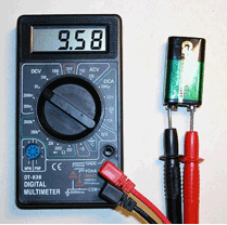 There is a reddish and black wire on the device. Reddish, as always in electrical engineering, is considered a plus. We plug it into the positive connector of the multimeter, which is not difficult to find if you read the inscriptions near the device sockets.
  If the polarity of the measured voltage is confused, nothing terrible will happen, just a minus will appear in front of the value on the screen.
  This is Chinese precision, almost 10 volts were found in the dead Krona... Now let’s check AC voltage measurement
household electrical network. We select the required position of the toggle switch and measure. This procedure should always be treated carefully; if it is positioned incorrectly, the device will fail. It goes without saying that before such experiments you need to make sure that the insulation of the tester’s wires and probes is in good condition.
This is Chinese precision, almost 10 volts were found in the dead Krona... Now let’s check AC voltage measurement
household electrical network. We select the required position of the toggle switch and measure. This procedure should always be treated carefully; if it is positioned incorrectly, the device will fail. It goes without saying that before such experiments you need to make sure that the insulation of the tester’s wires and probes is in good condition.  And now more carefully about the device... MULTIMETER DT-830B Consists of: - LCD display - multi-position switch - sockets for connecting probes - panel for testing transistors - back cover (will be needed to replace the device’s battery, a 9-volt “Krona” type element) The toggle switch positions are divided into sectors: OFF/on
-device power switch DСV
– constant current voltage measurement (voltmeter) ACV
– AC voltage measurement (voltmeter) hFe
– sector for switching on transistor measurement. 1.5v-9v
– checking power supply parts.
And now more carefully about the device... MULTIMETER DT-830B Consists of: - LCD display - multi-position switch - sockets for connecting probes - panel for testing transistors - back cover (will be needed to replace the device’s battery, a 9-volt “Krona” type element) The toggle switch positions are divided into sectors: OFF/on
-device power switch DСV
– constant current voltage measurement (voltmeter) ACV
– AC voltage measurement (voltmeter) hFe
– sector for switching on transistor measurement. 1.5v-9v
– checking power supply parts. 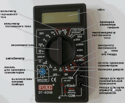 To conveniently explore the device, click on it. DCA
– measurement of constant current (ammeter). 10A
– ammeter sector for measuring huge values of constant current (according to the annotation, measurements are carried out within a few seconds). Diodik
-sector for checking diodes. Ohm - resistance measurement sector. Sector DCV
On this device The sector is divided into 5 ranges. Measurements are taken from 0 to 500 volts. We encounter high constant current voltage only when repairing a TV set. This device must be operated very carefully under enormous voltages. When switched to position “500″ volts on the display on the left top corner warning lights up H.V., that the highest level of measurement is turned on and when huge values occur, you need to be as careful as possible.
To conveniently explore the device, click on it. DCA
– measurement of constant current (ammeter). 10A
– ammeter sector for measuring huge values of constant current (according to the annotation, measurements are carried out within a few seconds). Diodik
-sector for checking diodes. Ohm - resistance measurement sector. Sector DCV
On this device The sector is divided into 5 ranges. Measurements are taken from 0 to 500 volts. We encounter high constant current voltage only when repairing a TV set. This device must be operated very carefully under enormous voltages. When switched to position “500″ volts on the display on the left top corner warning lights up H.V., that the highest level of measurement is turned on and when huge values occur, you need to be as careful as possible.  Typically, voltage measurements are carried out by switching large positions of the spectrum to the smallest ones if you do not understand the magnitude of the voltage being measured. For example, before measuring the voltage on the battery of a mobile phone or car, which says the highest voltage is 3 or 12 volts, we boldly set the sector to the position "20" volt. If we bet on the smallest, for example, on "2000" The millivolt device may fail. If we set it to huge, the device readings will be the least accurate. When you do not understand the value of the measured voltage (of course, within the framework of household electrical equipment, where it does not exceed the value of the device), then set it to the upper position “500″ volt and do frozen. In general, you can roughly measure, with an accuracy of 1 volt, at the position “500″ volt. If greater accuracy is required, switch to the lower position, only so that the value of the measured voltage does not exceed the value at the position of the device switch. This device is convenient in measuring direct current voltage in that it does not require strict adherence to polarity. If the polarity of the probes (“+” – reddish, “-” – black) does not coincide with the polarity of the measured voltage, the symbol will appear on the left side of the screen “-”
, and the value will correspond to the measured one.
Typically, voltage measurements are carried out by switching large positions of the spectrum to the smallest ones if you do not understand the magnitude of the voltage being measured. For example, before measuring the voltage on the battery of a mobile phone or car, which says the highest voltage is 3 or 12 volts, we boldly set the sector to the position "20" volt. If we bet on the smallest, for example, on "2000" The millivolt device may fail. If we set it to huge, the device readings will be the least accurate. When you do not understand the value of the measured voltage (of course, within the framework of household electrical equipment, where it does not exceed the value of the device), then set it to the upper position “500″ volt and do frozen. In general, you can roughly measure, with an accuracy of 1 volt, at the position “500″ volt. If greater accuracy is required, switch to the lower position, only so that the value of the measured voltage does not exceed the value at the position of the device switch. This device is convenient in measuring direct current voltage in that it does not require strict adherence to polarity. If the polarity of the probes (“+” – reddish, “-” – black) does not coincide with the polarity of the measured voltage, the symbol will appear on the left side of the screen “-”
, and the value will correspond to the measured one.  ACV sector The sector has 2 positions on this type of device – “500″ and “200″ volts. Handle measurements of 220-380 volts with great care. The procedure for measuring and setting positions is similar to the DCV sector.
It is a constant current milliammeter and is used to measure small currents, mainly in radio-electronic circuits. We don't need it yet. To avoid damage to the device, do not place the toggle switch on this sector; if you forget and begin to determine the voltage, the device will fail. In this regard, it is imperative to tell a mentor’s story. Being an inquisitive child and already knowing how to test an electronic circuit, for example, a lamp filament or a wire for a break, using a device, I did not distinguish between what voltage and current are. I don’t remember what happened to the device that I had, but I needed a “tester” to “ring” something for a break. I asked a friend. Vasya took it from his dad. A good Russian pointer Ts-2...I don’t remember which one, Vasya gave it to me. Having measured what was needed, I put the device aside and forgot about it. And I remembered when I saw that it was written on the socket in the wall 220 V 6A. Either I wanted to make sure of the accuracy of the device, or the consistency of what was written on the socket, in short, I measured the voltage, it matched. Naturally, the toggle switch was on voltage measurement, as expected. Now, without thinking twice, I put the toggle switch in position 10
and measure the current and insert probes into mysterious holes in the wall. I don’t remember such an explosion in my entire life. The device broke into blackened fragments, the face was like a Neger in the darkness, his ears were laid for half an hour, there was no one at home perfectly, so he would have received a “full program”. So, before you try to do something, at the slightest suspicion of the presence of voltage, you need to know simple things: what current, voltage, resistance are. So let's move on. There is still a position 10 A constant current measurements (amperemeter). Measurements are performed by moving the wire from the second socket to the socket 10 A. If you need to determine the current of an electrical appliance, you can use an ammeter, but again with great caution. The annotation for the device says that current measurements can be taken in a few seconds, but I would not recommend using this opportunity again. If you read home lessons, you will find out that there are other methods to find out the approximate value of the current and this will be more than enough for us. Resistance measurement sector
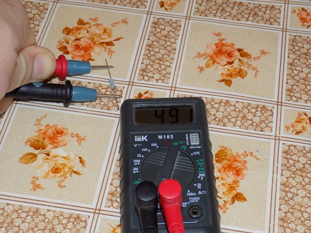
(ohmmeter). Broken by position from 200 Ohm to 2 Mohm(2,000,000 ohms). Resistance can be determined from 1 Ohm to 2 Mohm with the following aspects: Firstly: the Chinese multimeter is not a clear instrument and the error in its readings is quite large. Secondly: unpredictable high sensitivity for clear measurements. In this regard, when the probes are connected to each other, the device indicates the resistance of the circuit, which should not be neglected, but considered as the resistance of the wire on the probes, i.e. when measuring small resistances, it is necessary to subtract from the result the value acquired when the probes are short-circuited. For example: we measure the resistance of the lamp, because the lamp has a tiny resistance, put it in position 200 Ohm. First, let's connect the probes to each other. I have the device showed 0.9 Ohm- we will subtract this after measuring the resistance that suits us. We measure on the lamp, we get 70.8 – 0,9 = 69.9
Ohm. Please note that the readings are approximate, but in our cases with household electrical appliances this is enough. Working up the sector spectrum is not difficult. If your display shows one on the left, then the resistance is greater than the set position of the toggle switch, and if there is one on the display when the switch is in 2000KOhm position, then the circuit can be considered open. When numbers appear, there is some resistance in the circuit. 
Battery replacement: If you notice a glitch on the screen, numbers disappear or the readings do not correspond to the approximate values, it means it’s time to change the battery. Small Phillips screwdriver - back cover - new element9 V.
Sector Diodik: Indicates the voltage drop across the junction, from 400 to 700 mV in the forward direction on a working diode and infinity, i.e. unit on the left in the reverse direction. On a faulty one, in both directions: 1. Close to zero – breakdown value. 2. Close to infinity – break. Sector hFE For measuring transistors, there is a socket indicating which socket and which leg of the transistor to place. The transistors of both are checked n – p – n And r – p -r conductivity for breakdown, break. Indicates the static current transfer coefficient (silicon - CT only).
Even if you are not a professional electrician, you should have basic instruments for measuring electrical quantities in your home. In order to measure the voltage in the network, or ring a fuse, it is not necessary to call a paid technician. All this can be done using a simple device - a multimeter or tester. They are different sizes, cost. Functionality from the most primitive, to measuring temperature and light level.
To ensure that the money invested in this device is not wasted, you need to know how to use the tester correctly. First, let's look at typical device, and its basic functions.
What a simple multimeter can do and how to use it correctly
It requires power to make it work. A regular 1.5 volt battery is not suitable; a higher voltage is needed. In models with a large case, Krona type batteries can be used: 6F22, 1606 and others, with a voltage of 9 volts. Compact models are equipped with an A23 battery with a voltage of 12 volts. In the event of a critical discharge, the device will signal that it is impossible to carry out measurements; only the dialing mode will remain. The fact is that digital instruments use electronic circuit, which requires a certain voltage to operate.
Pointer instruments for measuring current or voltage can operate autonomously.

But even pointer testers require power to measure the resistance of a resistor or check the health of a diode.
So, the battery is installed, the tester is ready for use. We will look at a popular digital model; dial multimeters are almost never seen in everyday life.
Before starting work (or, more correctly, purchasing a device), you need to understand why you need it. What should be the measurement limits, accuracy class, additional functions. For example, for household use no need to take current clamps with a measurement limit of hundreds of amperes. Functions such as measuring temperature, sound and light intensity, and humidity are certainly useful. But additional sensors increase the cost of the device, and you will use them extremely rarely.
For user convenience, many manufacturers add screen backlighting, stands, and storage cases.

This allows you to work with the device more comfortably, you just pay for each option.
In fact, the following functions are sufficient for most tasks:
- Measurement of alternating and direct voltage in the range up to 500 volts.
- Measurement of resistance and line continuity with a sound indicator.
- Current measurement up to 2 amperes.
Additional options that are almost always available even in inexpensive models:
- Checking transistors.
- Testing capacitors, sometimes with the ability to measure capacitance.
- Checking the serviceability and direction of conduction of diodes.
- Checking LEDs.
The measurement is quite simple: the control handle is set to the required mode.
The measurement limit is selected as close as possible to the expected value, but not less. For example, if you are testing the voltage on a 12 volt battery, the measurement limit is set to 15 volts (depending on the model). Then you should securely fasten the measuring cables in the sockets and connect the probes to the measuring points.
Safety precautions when working with the tester
- Before starting work, read the “safety” section in the instructions.
- Make sure that the housing is intact and that the connecting screws are fully tightened. In many devices, replacing the battery requires disassembling the housing. Many users then simply snap the halves together, forgetting to secure the screws.
- Check the reliability of the connection of the measuring cables in the connectors. To do this, it is enough to pull the wire with a little effort while holding the insulator in your hands.
- When working with voltage greater than 60 volts, do not hold both test leads different hands. By fulfilling this simple requirement, you will protect yourself from electric shock along the so-called “line of death”: hand-heart-hand.
Typical measurements with a household multimeter
DC current measurement
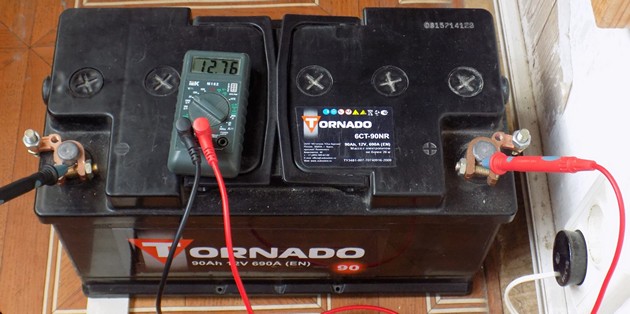
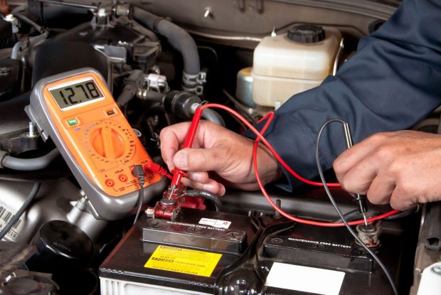
Measurement of direct current of safe value. For example - check car battery. Mode setting: DC voltage measurement. The measurement limit is 20 volts (closest range). The measuring cables are connected in accordance with the instructions.
How to check batteries or accumulators
We check AA batteries or accumulators in a similar way. The measurement limit in our case is the same 20 volts DC voltage. The estimated value is 1.4 volts. We press the contacts to the battery (observing polarity) and take readings.
![]()
Hazardous Voltage Measurement
Attention! Only persons with the appropriate clearance groups may work with dangerous voltage!
Measuring dangerous voltage: for example, in a socket network. First, let's check the measuring cables. The insulating handles must be intact and the wires must be securely held. Restrictive rings are molded onto the measuring cable to prevent fingers from slipping into the danger zone when pressing against the contacts being measured.

We set the alternating current measurement mode, the measurement limit is 500 (or 750) volts (measured voltage 220 volts). We securely fix the cables in the device, connect to the outlet, manipulating with one hand.

To measure the voltage in the network, a few seconds are enough. Do not leave the device connected to the outlet for a long time.
Chain continuity
Having figured out how to use a voltage tester, we move on to the simplest operation: checking the continuity of the circuit.
Attention! It is permissible to perform testing only on completely de-energized sections of the circuit.
This is done when such a mode is available on the device.

Before starting the dialing test, we connect the probes together and check the functionality of the device (stable sound signal). If the ends of the wiring being tested are far apart, use an extension cord.
Important! To allow you to safely work on mains wiring in test mode, you must physically disconnect the line being tested at the nearest junction box.
Checking radio components
Of course, parts should be checked after they are removed from the circuit board. As a last resort, it is enough to disconnect one contact.
Checking a diode or resistor. We set the appropriate mode on the switch. If you do not know the approximate value, we start measuring from a higher limit. By switching the measurement range, you will sooner or later find the desired value.
LEDs are checked in dialing mode. Even if you see that the diode is properly conducting current in one direction (in the test mode for conventional diodes), but does not light up, the measurements do not matter.
In dialing mode, the current will be sufficient to ignite the crystal. Reversing the polarity will not damage the part. The diode just won't light up.

You need to know this: Even economy class testers have some overload protection and a fuse on the input contacts.
But this does not mean that you can confuse the modes and connect to a high voltage with a low measurement threshold set.
How to check grounding
Grounding measurements can also be made using a household tester.

How to check grounding without an indicator screwdriver
To do this, you need to use a tester to check the voltage between all pairs of contacts. Of course, this makes sense if there is a wire connected to the ground pin of the outlet.
A voltage close to 220 volts will only be between the pairs: phase-zero and phase-ground. It is clear that the phase cannot be connected to the grounding contacts of the socket; therefore, it is in one of the working holes.
You already know how to use a tester to check natural grounding (with a known phase contact).
Learn more about current measurement
In principle, everyone who studied physics at school knows how to measure the current strength in a section of a circuit. It is necessary to pass current through the device: that is, connect it to the open circuit. In laboratory conditions it is simple, there are verified parameters and a device with a safety margin. How, for example, can you check for current leakage on a car battery?
Not every tester is suitable for this type of work. The current measurement limit must, at a minimum, exceed the power of the headlight lamps. For example, you have 55 W halogen headlights. Total power 110 W, divided by the voltage of 12 volts, we get a value of about 10 amperes. This means that the household tester must have a DC current measurement mode with a limit of 20 amperes.
- Disconnect the negative wire (ground) from the battery.
- We securely connect the negative measuring cable of the tester to the negative terminal of the battery.
- We connect the positive measuring cable of the device to the negative wire of the car.
There should not be zero current: under constant nutrition There is an on-board computer, radio, alarm system (if equipped). But these are tens of milliamps. If the value is an order of magnitude higher, the tester will help you find the problem area.
How to choose the right multimeter
A clear recommendation for those who are not interested in radio electronics is a basic digital tester of the 830, 832 or 182 series. Its price is several hundred rubles. The only drawback of such a device is the small current measurement range. However, it is sufficient for household measurements.
If you service the car yourself, you should choose a model with a strong rubberized casing, with a current measurement limit of at least 10 amperes.
Such a device will cost about 1000 rubles, but its safety margin is higher.
Purchasing pointer testers today does not make sense. Perhaps for specific tasks, when it is necessary to monitor certain impulses in real time.
Video on the topic
Hello, dear guests of the site.
Well, I finally got around to writing an article on the topic of how to use a multimeter. A lot of letters come from you on this issue. Mainly interested in how to carry out this or that measurement. But first things first.
In general, I think that a multimeter is one of the most necessary devices for diagnostics and repairs, both in production and at home. That's why it's always present in mine. With its help you can carry out a large number of:
- AC voltage and current
- constant voltage and current
- electrical resistance
- containers
- frequencies
- temperature
- parameters of transistors and diodes
By the way, even recently, instead of multimeters, we used analog (pointer) devices of the “Ts4342” type. Or maybe someone still uses it.
![]()
In common people they are simply called “tseshka”.
That’s why, to this day, I call the multimeter a “tseshka.” It just so happened - I got used to it.
I like multimeters for their simplicity and versatility. However, it is worth noting here the direct proportional dependence functionality of the multimeter depending on the price. The more expensive the multimeter, the wider its capabilities. Don't forget about quality.
Personally, I use the following multimeters (“testers”):
- Fluke 123
- М4583/2Ц
- М890D
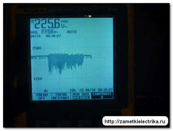
Fluke 123 is a professional multimeter, and according to the passport, an oscilloscope. And his price is appropriate. The photo below shows a graph of the supply voltage of 220 (V) at one of the substations, made by a Fluke 123 device. And as can be seen from the graph, the voltage is not very stable at some hours. As a result, it turned out that at night someone had unauthorizedly connected to the 380/220 (V) assembly and carried out welding work. The culprit was discovered and punished. Thanks to the device for accurate and reliable information.
Other multimeters are simpler and cheaper.


Therefore, in this article I will tell you how to use a simple M890D digital multimeter.
In terms of dimensions, the M890D multimeter is very small and compact, and is portable. Its kit includes test leads (red and black).

I want to warn you right away so that you are not surprised when you see blue electrical tape on the probes. This is the “disease” of all low-quality probes.

The point is that when active use multimeter, the wires often break. This happens due to the fact that the wire running in the probe tube is held only by the soldering of the metal terminal and rotates freely. The way out of this situation, in addition to fixing the wire to the tube using electrical tape, is to purchase high-quality probes. For example, these:

The power source for the multimeter is a 9 (V) Krona battery, which is located inside the case. To replace the battery, you need to unscrew the screw on the back cover of the multimeter.

A protective fuse is also installed there.

Introduction
First, let's get to know externally multimeter. In almost all multimeters, the measured parameters are divided into sectors outlined by corresponding lines. In the center there is a switch with which you select the required parameter and measurement limit.

The multimeter is turned off by pressing the “auto off power” button.

For some models, the multimeter is turned off by moving the switch to the “off” position.
Electrical safety when working with a multimeter (“tester”)
When working with a multimeter, you must strictly observe following rules By .
- Do not use the multimeter in a humid environment
- It is prohibited to change the switch position and measurement limit when taking measurements
- It is prohibited to measure a parameter above the upper measurement limit of the device
- It is forbidden to use a multimeter if the test leads are faulty
How to use a multimeter when measuring DC voltage
When measuring DC voltage with a multimeter, insert the red measuring probe into the “V/Ω” socket, and the black probe into the “com” socket.


It is customary to take the red probe as the “+” potential, and the black probe as the “-” potential.
Set the multimeter switch to range (-V). It is specially highlighted green. There are 5 measurement limits in this range: 200 (mV), 2 (V), 20 (V), 200 (V) and 1000 (V).

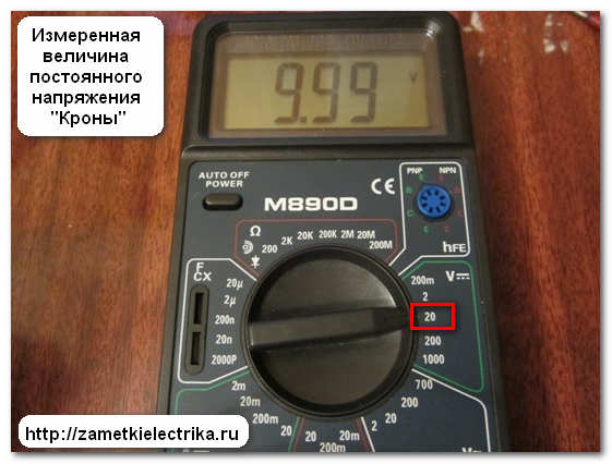
For example, let’s measure the DC voltage on a Krona type battery (battery) with a voltage of 9 (V).

Therefore, you can immediately set the switch to the “20” limit, which will correspond to the multimeter’s measurement limit from o to 20 (V). We connect the measuring probes to the object being measured at the “+” and “-” contacts of the battery.

On the display we look at the constant voltage value, which is 9.99 (V). Almost 10 (B).
You see, there is nothing complicated.
If on the display screen of a multimeter (tester) there is a minus sign in front of the value, this means that the wrong polarity is selected - you need to swap the measuring probes.

What to do when the magnitude of the measured DC voltage is unknown?
When the value of the measured direct voltage is unknown, the measurement must be started from the maximum limit of “1000”, which will correspond to the measurement limit of the multimeter from o to 1000 (V). I talked about this a little higher, otherwise you can burn the multimeter.
Let's assume that we don't know the voltage of our "Crown". Then we set the multimeter switch to the limit “1000” and take the measurement. In this case, we will see the value 008 (B) on the tester screen. The resulting value is immediately preceded by two zeros - this indicates that the measurement limit can be reduced.

Next, use the switch to set the limit to “200”, which will correspond to the measurement limit of the multimeter from o to 200 (V), and take the measurement again. Now on the multimeter screen we see a reading other than zero, and it is 09.9 (V). But the value is again preceded by a zero, which indicates that the measurement limit can be reduced again.

Once again we lower the measurement limit of the multimeter and set it to the limit of “20”. And only after that the real value of the measured constant voltage of the “Krona” was displayed on our display screen and it was 10 (V).

I think we've sorted this out.
There are times when the value “1” appears on the display of a multimeter (tester).

This means that the selected measurement limit is selected lower than the value of the measured quantity.
How to use a multimeter when measuring AC voltage
When measuring alternating voltage with a multimeter, insert the red measuring probe into the “V/Ω” socket, and the black probe into the “com” socket. In general, as when measuring DC voltage.
Set the multimeter switch to the range (~V). It is specially highlighted in white. There are 4 measurement limits in this range: 2 (V), 20 (V), 200 (V) and 700 (V).

) is about 220 (V) depending on the load on your supply transformer. At least that's how it should be. At the same time, let’s check how much the voltage in our house differs from the “ideal” one.
We set the multimeter switch to the “700” limit, which will correspond to the multimeter’s measurement limit from o to 700 (V), and measure the alternating voltage in the home network. When measuring, the measuring probes can be inserted in any order and swapped.
I told you about electrical safety when taking measurements with a multimeter at the beginning of the article.

The measured AC voltage of the home network, which we see on the multimeter screen, is 231 (V).
By the way, in some of my articles I have already given examples of using a multimeter when measuring various parameters chains. For example, in articles about
A multimeter or tester is multifunction device, which allows you to measure current, voltage, resistance, as well as other indicators of the electrical network and household appliances. Home craftsmen can use such devices to check the serviceability of sockets, electrical cables, computer wires, and batteries of digital equipment.
Types and features of modern testers
Currently, there are two types of devices used to measure the characteristics of electrical networks - digital and analog. Analog instruments are equipped with magnetic needles and measurement scales on which the values of quantities are indicated. Analogue devices are still very popular due to their low cost and reliability, but they also have significant disadvantages:
- small signatures on scales;
- small divisions;
- the impossibility of accurately determining values due to oscillation of the needle;
- the need to convert units when taking measurements.
A modern digital device is equipped with a liquid crystal screen on which the results are displayed. enjoy digital tester very simple, it allows you to obtain the most accurate data and does not require conversion of values. Such devices often have additional functions performed temperature sensors, special frequency meters and other devices. During operation, the display shows an animated scale that allows you to measure vibrations.
Understanding the interface and learning how to connect wires
Before you start using the tester, you need to understand the design and interface of the device. On outside The panel has three outlets for connecting wires. Each output is intended for different:
- COM or “–” – connection of the black wire;
- 10A – for connecting the red probe, used when measuring current up to 10 amperes;
- VRmA or " " - used to connect a red wire, used to check various quantities and indicators, including current strength above 10 amperes.
Some modern devices may have four outputs:
- 10 or 20A – for current measurement;
- mA – to check the current in milliamps;
- COM – connection of the black wire;
- VΩHz – any other measurements.
Some multimeters on the market have an additional output designed for testing transistors. In the central part of the device there is a circular switch necessary for setting the measurement limits (in four or more regions). Next to the circular switch there are symbols that allow you to correctly set its position:
- DCV (V=) – constant voltage mode with permissible limits of 10, 20, 200 or 1000 V;
- ACV (V~) – alternating voltage mode with limits of 200 or 750 V;
- DCA (A=) – DC current measurement range in the range from 0.5 mA to 500 mA;
- Ω – resistance test area in the range from 200 Ohm to 2 MOhm.
The multimeter switch can be moved to other positions:
- Off – switch off;
- 10A – measurement of current less than 10 A;
- Temp – temperature check;
- Continuity - determining the location of a cable break;
- Hfe – transistor test.
To use a multimeter correctly, you need to know approximately the limits of the measurements being performed. If you don’t even know the limits approximately, then you need to set them to the maximum values and take the first measurement. The device will indicate an approximate value and allow you to more accurately set the limits of subsequent measurements.
Measuring various characteristics of the electrical network with a multimeter
The entire procedure for checking electrical network parameters includes three stages. First, the wires are connected, then the regulator is set to the appropriate position, and at the end, measurements are made with the necessary adjustments. However, measuring various electrical system parameters has its own unique characteristics.
To test DC voltage with a tester, you should set the switch in the DCV zone to the maximum possible value - 750 or 1000 V. Now you need to connect the wires: red to the VRmA output, and black to the COM output, and then connect them to the device or network being tested. Then you can take the first measurement. Based on the obtained indicators, the regulator value should be reduced to desired value and repeat the work. For example, if a measurement is taken in car wiring, you will see a voltage within 12 V, which means the next measurement should be performed with a limit of 20 V.
When examining the electrical system in a house or apartment, it is often necessary to measure AC voltage. To do this, you need to connect black (to the COM output) and red (to the VRmA output) probes to the device. The regulator needs to be set to the ACV position, and set the measurement value to 600–750 V. Considering that in a standard outlet the alternating voltage is about 220 V, you should not set the value on the multimeter to 200 V, as the device may burn out. The probes of the device should be installed in the holes of the socket being tested, after which the device display should show real values voltage.
To check the resistance on the resistor, set the regulator in the Ω region to a value from 200 Ohms to 2000 kOhms. The limit should be set in accordance with the marking on the resistor. If the resistor is marked 1K5, then measurements should be taken within 2000 Ohms, and for a resistor marked 560 - 2000 kOhms. When the resistance value is not set, you need to set the minimum limit and perform the measurement. If the number 1 appears on the display, then the limit must be increased and measurements taken again. The procedure will have to be repeated until the resistance value appears on the display instead of one.
Most testers can only measure D.C., only some models provide a mechanism for switching probes to measure alternating current. To measure direct current, set the regulator to the 10 A or DCA position (depending on the expected value). Then the probes are connected to the device: black - to COM, red - to 10 A or VRmA. Now you need to select the measurement limit from 200 µ to 200 mA. Next, you can connect the probes to the electrical network, after which the amount of current in the electrical system will be displayed on the screen.
If the electric multimeter has a dialing function, then the device can check the network for breaks. To do this, you need to set the regulator to the appropriate zone, which is usually indicated by the image of a sound wave or speaker. Next, the wires with probes are connected to the device, and the probes are applied to the edges of the circuit section being tested (de-energized). If the circuit is closed, you will hear a special signal; if there is a break, there will be no sound indication.
A multimeter can often also test diodes. The diode passes current in one direction, so it is very important to connect the wires to the element being tested in correct sequence. The check itself goes as follows:
- connect the wires to the device;
- set the switch to diode test mode;
- We connect the black (negative) wire to the cathode, the red (positive) wire to the anode.
- look at the voltage value on the screen, it will be no less than 100 and no more than 800 mV;
- We swap the wires and take the measurement again, if the result is no more than 1, then the diode is working.
If both tests show 1, then the diode passes current in both directions, which means it is faulty. You can check the operation of the LED in exactly the same way - a working LED will light up when you connect the wires from the tester.
One more useful function The multimeter is able to test transistors. To check, you must use the device in resistance test mode. NPN transistors can be thought of as back-to-back diodes. To check them, you need to connect the wires to the multimeter and set the regulator to the Ω position. The red wire should be connected to the base terminal using an alligator clip. The probe on the black wire is connected alternately to the other terminals - emitter and collector.
The results obtained during the work should be the same as when checking the diode. When replacing the black and red probes, the value on the screen should be equal to 1, which indicates the serviceability of the transistor. Examination pnp transistor is performed in exactly the same way, but the positive and negative probes are initially swapped.
If you need a device to test a cable or whole cable line, then a regular multimeter will not work for this. To perform such measurements, special cable testers are used. With their help, you can determine the wiring diagram, attenuation, crosstalk at the near end of the cable, return loss, etc.
Differences in using an analog and digital tester
The very principle of operation of an analog tester is exactly the same as the principle of using digital equipment described above. However, the use analog devices has a number individual characteristics. To measure, the device must be calibrated. To do this, you need to set the needle to zero by tightening the knob located under the digital scale.
When determining voltage, you must first select constant or alternating voltage using the appropriate buttons. And when you need to move from smaller units to larger ones, you need to use a trimming resistor. Otherwise, the settings and use of analog and digital devices are the same.
Scales for taking readings:
- alternating voltage – black scale V, mA, or red 10V, AC (depending on the selected limits);
- constant voltage – black scale V, mA;
- direct current – black scale V, mA;
- resistance – green scale Ω.
When using analog multimeters, it should be taken into account that the accuracy of the readings obtained will depend on the position of the arrow, therefore it is very important to securely install the device on flat surface(for all existing legs).
Work with electrical system always involves serious risks, therefore, in order not to endanger your health and the equipment you use, you must follow safety rules. First, the test leads must be installed in the appropriate sockets after selecting the range and measurement limits. Secondly, you cannot connect the probes to the electrical circuit before the measurement mode is set. Thirdly, without knowing the approximate value of the values in the network, it is necessary to start working with large values(the exception is resistance measurements).
In addition, when measuring voltage in a network of more than 60 V, you should not hold the probes with both hands, as there is a risk of electric shock. If you need to measure voltage in the network from 380 V and above, use special high-voltage wires and devices with anti-slip stops. To buy a functional device for your home, first determine why you need a multimeter. Testers vary greatly in type, accuracy and features. All of them allow you to measure voltage, resistance, current, but only the most expensive ones can perform other measurements.
A tester is colloquially called a digital device for measuring parameters. electrical circuit- multimeter (emphasis on the last syllable). But how does it then differ from an ammeter, voltmeter or ohmmeter, you ask, why was this device needed when there are others?
The fact is that a multimeter is three devices in one, which is where its name comes from; the prefix “multi” means a lot.
But of course, the tester may not be limited to only three components, but contain 10, 20, and sometimes 30 different devices, and all this in one small box, slightly larger in size than a smartphone.
Which is better - an analog tester or a digital one?
All devices in the world were originally analog, and today they are gradually being replaced by digital ones. The latter have many advantages, for example, measurement accuracy; the human eye can make mistakes, while a value down to thousandths appears on the screen.
However, many "old school" professionals prefer analog devices because they are simpler, easier to repair, and much cheaper.
How to prepare the tester for work
- Preparing a multimeter consists of the following steps: Connecting the power supply.
- Next you need to connect the probes. Probes are wires with which contact will be created for the flow of electric current through the tester, the red wire must be inserted into the socket where it says COM, and the black wire where it says V.
- Sample of probes. To use a multimeter and get accurate results, you need to make sure the wires are intact and in good condition. Connect the terminals to each other and you will hear a beep - this will mean that everything is in order with the probes.
- Select measured value, and set it on the scale by turning the pointer knob.
- Select size, that is, in what fractions the value of the quantity will be displayed on the screen.
The tester is ready to go!
Electronic tester device
Instructions for use
Modern multimeters allow you to measure great amount quantities, but its main purpose is to determine current, voltage and resistance.
How to measure voltage with a tester
A multimeter can measure parameters of both direct current and alternating current. For example, consider the case of measuring voltage in a household outlet. All homemade electrical network works for alternating current, so place the tester’s pointer in the ACV digit for a dimension greater than 220.
Then you need to insert the probes into the socket (it doesn’t matter which probe, which hole you insert into), just do not touch their metal parts, hold only the insulation, and also do not touch them to each other while they are in the socket. Most likely, your device will show a voltage value of 215.5 V, as is usually the case.
If you measure DC voltage, then the algorithm will be the same, only the arrow should be directed to the DCV section. You can measure the voltage of a AA battery.
To do this, take the probes and attach them to the battery contacts; here, as in the case of a socket, the polarity does not matter, since the same value will always be displayed on the screen, only with different signs. Since the battery voltage is usually low, the probes can be pressed directly to the terminals with your hands.

The entire home electrical network runs on alternating current, so set the tester's pointer to the ACV digit to a dimension greater than 220
How to measure current
In order for the current value to be displayed on the display, you need to select this value on the scale, that is, turn the arrow to the section with the letter A. If you measure direct current, then on DCA, and if alternating, then on ACA. Although, as a rule, in everyday life it is necessary to measure only the voltage, sometimes there is still a need to accurately determine the current strength, for example, when checking car batteries.
How to measure resistance
Everything is the same, just turn the pointer knob to the Ω (Omega) section. If you expect that the resistance will be high, you can choose the dimension in terraohms - this is a lot, usually dielectrics have this resistance, but if you are measuring the resistance of an ordinary conductor, for example, aluminum wire, it is enough to simply select Ohms.

In order for the current value to be displayed on the display, you must select this value on the scale, that is, turn the arrow to the section with the letter A
Diode ringing
Using a tester, you can also check diodes for functionality. Diodes, for those who don’t know or have forgotten, these are special devices, which conduct current only in one direction, which is why they are also called AC rectifiers.
Switch the multimeter handle to the “diode test” position - this is a triangle with a stick on top, then connect the probes to its electrodes twice, changing the polarity.
If the diode is working, then in one polarity you will get a value on the screen from 400 to 800, and the other 1. This will mean that in the first case the diode passes current and there is voltage on it, but in the second there is no.

In the case of an LED, the procedure remains the same, but the procedure itself is greatly simplified. Since the LED glows when electric current is passed through it, you will immediately know whether it is working or broken.
Additional tester features
Measuring capacitance of capacitors
Some multimeters have a built-in capacitance measurement function (in Farads). And although, as a rule, the average user will most likely never need it in their life, for radio amateurs it will be very useful, because often capacitors on the secondary raw materials market (which is where most amateurs buy parts) are of poor quality, and sometimes there is even outright fraud, however, if If you carry a tester with you to the store, your money will not be wasted.
Sometimes when repairing a car, you may suspect that a transistor is faulty, but checking it with a tester is very simple. It is necessary to consider pairs of its electrodes as diodes and ring them all in both directions.
So for an NPN transistor, the Base-Emitter diode must have one-way conductivity, the Base-Collector diode must do the same, and the Emitter-Collector diode must not conduct current in any direction, that is, be an insulator.
For a PNP junction transistor, the first two diodes must conduct current in the opposite direction.
In addition, the tester can:
- You can come up with hundreds of other ways to use a multimeter, we leave this for you as homework. Many people like to press the conductive parts of the tester probes directly to the terminals of the device under test. , and despite the fact that in most cases this does not pose a danger to life and health due to the very low voltage
- However, it is not recommended to do this. The fact is that the fat from your hands transfers to the metal, and then oxidation processes begin, which reduce the conductivity of the probes, which means that their service life is reduced.