Home > Books > Electronics
2.8. Parallel connection R, L, C
If to the clamps electrical circuit, consisting of parallel connected elements R, L, C(Figure 2.18), harmonic voltage applied u = Umcosωt, then the harmonic current passing through this circuit is equal to the algebraic sum of the harmonic currents in parallel branches (Kirchhoff’s first law): i = iR + iL + iC.
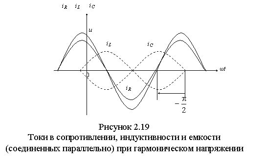
Current iR in resistance R in phase with voltage And, current iL in inductance L lags behind, and the current iC in a container WITH leads the voltage by π /2 (Figure 2.19).
Therefore, the total current i in the circuit is equal
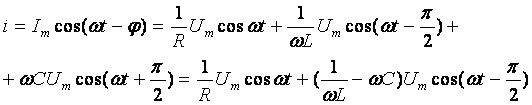 (2.20)
Equation (2.20) is a trigonometric form of writing Kirchhoff's first law for instantaneous current values. The quantity included in it  called reactive conductivity of the circuit
, which, depending on the sign, may have an inductive (b > 0) or capacitive (b< 0)
character. Unlike reactive conductivity b conductance g = l/R always positive.
called reactive conductivity of the circuit
, which, depending on the sign, may have an inductive (b > 0) or capacitive (b< 0)
character. Unlike reactive conductivity b conductance g = l/R always positive.
To find Im and φ we will use the vector diagram corresponding to equation (2.20) (Figure 2.20, a and b). Right triangle with legs IR And and hypotenuse I called the current triangle. The current triangle is constructed in Figure 2.20, A For b >0, and in Figure 2.20, b− for b< 0 .
From the current triangle it follows that ![]() or I = yU; Im=yUm
or I = yU; Im=yUm
Here  (2.21)
total conductivity of the parallel circuit under consideration.
Active, reactive and admittance are among the basic concepts used in the theory of electrical circuits.
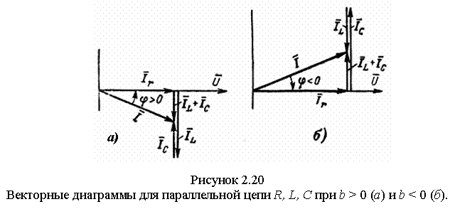
Current phase shift angle i relative to voltage and is equal to:
 . (2.22)
If the voltage is set u = Umcos(ωt + y) on circuit terminals with parallel connected R, L And WITH, then the current is determined by the formula
i = yUmcos(ωt + y - φ ).
Angle φ, as in the previous case, is measured on the time diagram ωt from voltage to current, and in a vector diagram - from current to voltage; it is an acute or right angle
|φ | .
Corner φ positive when the circuit is inductive, i.e. at b > 0; in this case, the current lags in phase from the voltage. The angle φ is negative when the circuit is capacitive, i.e. at b< 0 ; In this case, the current is ahead of the voltage in phase. The current is in phase with the voltage at b = bR - bC = 0, i.e. with equal inductive and capacitive conductivities. This mode of operation of an electrical circuit is called current resonance.
From (2.21) and (2.22) it follows that the active and reactive conductivities of the circuit are related to the total conductivity by the formulas:
g = ycosφ; b = уsinφ. (2.23)
Multiplying the right and left sides of expressions (2.23) by the effective voltage value U, we obtain the effective values of the currents in the branches with active and reactive conductivities, depicted by the legs of the current triangle and called the active and reactive current components:
Ia = gU = ycosφ U = Icosφ;
Ip = bU = ysinφ U = Isinφ.
As can be seen from the current triangles and equations (2.24), the active and reactive components of the current are related to the effective value of the total current by the formula
![]() .
.
Dividing the sides of the current triangle into U, we get right triangle conductivity, similar to the voltage triangle (Figure 2.21, a, b).

The conductivity triangle serves as a geometric interpretation of equations (2.21) and (2.22); conductance g is plotted along the horizontal axis to the right, and the reactive conductivity b depending on its sign it is postponed downwards (b > 0) or up (b< 0) .
The angle φ in the conductivity triangle is measured from the hypotenuse y to the leg g, which corresponds to the reading φ in the triangle of currents from I = yU To Ia = gU.
To characterize capacitors represented by a circuit with capacitive and active conductivity, the concept of capacitor quality factor is used QC = b/g = ωCR, which is equivalent to the tangent of the angle |φ | capacitor. The reciprocal quantity is called the dielectric loss tangent of the capacitor tgδ = l/QC(the dielectric loss angle δ complements the angle |φ| up to 90°).
How more resistance R, the greater (other things being equal) the quality factor of the capacitor and the smaller the loss angle.
The quality factor of capacitors for different frequencies and dielectrics varies widely, from approximately 100 to 5000. Mica capacitors have a higher quality factor than ceramic ones. The quality factor of capacitors used in high-frequency technology is approximately 10 times higher than the quality factor of inductive coils.
The capacitive voltage lags the current in phase by a quarter of a period (90 0)
Sequential analysisRLC - circuits under harmonic influence

Based on Kirchhoff's second law u = u R +u C +u L or in a comprehensive
form
U=U R+ U C+ U L. Taking into account
 we get
where is the complex resistance RLC- chains
Transforming, we get that,
where is the reactance, is the total resistance of the circuit, and is the phase angle RLC chains.
Let's write Ohm's law in complex form, taking into account phase relationships:
. Here ![]() .
.
Resistance triangle in RLC– chains.
- total resistance RLC- chains,
phase angle RLC- chains.
Let's consider dependencies impedance Z and phase angle φ in sequential RLC- circuits depending on frequency. At some frequency ω 0 the equality can be satisfied

Let's consider the voltages across the inductance and capacitance
; 
Chart options U L . U C V RLC– chains. The graphs may or may not have maxima (this depends on the ratio of the values of the elements).
Vector sequential diagramsRLC -chains
A set of several vectors displaying currents and voltages in a circuit is called a vector diagram. For a series RLC circuit, the diagram is constructed by plotting the current horizontally, then also plotting the resistive voltage vector on a scale in the direction of the current, then plotting the inductive voltage vector perpendicularly upward from its end and the capacitive voltage vector from its end downwards.
The appearance of the diagrams depends on the selected frequency in relation to the resonant one.
1) ω<ω 0 , U L< U C
2) ω=ω 0 → U L =U Cφ=0
3) ω>ω 0 . U L > U C
Parallel RLC circuits
U=I· Z=I/Y ![]() Y
– complex conductivity, B– reactive Consider a circuit with parallel RLC- elements:
Y
– complex conductivity, B– reactive Consider a circuit with parallel RLC- elements:
All its elements are connected in parallel and are under the same voltage u(t)=Um▪sin(wt+y u). It is necessary to determine the current in the circuit i(t). Based on Kirchhoff’s 1st law, at any moment in time the following relation is true:
i(t)=i R (t)+i L (t)+i C (t) .
The individual current components are determined by the expressions
Substituting instead u(t) harmonic function of time and carrying out the necessary mathematical operations, we obtain
We will define the required current in the form i(t)=Im▪sin(wt+ y i).
Let's move on to complex instantaneous values.
Reducing by e j w t and taking into account that , we get ![]()
or
The expression in parentheses is the complex conductivity of the circuit Y
 , – resistive component of conductivity,
– reactive component of conductivity. and it can be equal to 0
at some frequency ω 0, which is called resonant.
Ohm's law in complex form for a circuit is written
or
It follows that when parallel connection branches of the circuit, the complex equivalent conductance is equal to the sum of the complex conductivities of the branches:
Let's analyze the vector diagram of a parallel RLC circuit
The voltage is taken as a reference vector, the current in the resistor is in phase with the voltage, the current in the inductance lags behind by 90 0, and the capacitive current leads by 90 0 or less (ω<ω 0). Общий ток равен сумме векторов всех токов и он отстает от напряжения по фазе.
The principle of duality in electrical circuits
In electrical circuits there are some concepts that, on the one hand, are opposite to each other, and on the other hand, are interconnected and complement each other (from physics: electromagnetic field - electric field and magnetic field). Such concepts and quantities are called dual.
For dual quantities, the notation forms and mathematical equations are the same.
Voltage current
Contour node
Kirchhoff's law 2 Kirchhoff's law
Conductivity resistance
U=I· ZI=U· Y
Series circuit parallel circuit
IIN IIT
The formulas obtained for a certain chain can be formally extended to dual quantities in a dual chain. Dual quantities behave identically in dual chains, and the same ones will behave oppositely under the same conditions.
Example 2 Here E1 is a source of constant emf, and j2 is a source of alternating current.
In this case, we can only use the overlay method. Let's make two equivalent circuits, in the first of which partial currents from a source of constant emf are calculated. Therefore, in it the inductance is replaced by a jumper, and the capacitance is replaced by a gap. In the second scheme, partial currents from an alternating current source are calculated and here it is necessary to convert all currents, voltages and resistances into complex form and write down Kirchhoff’s laws in complex form.
|

I 1 E 1 =E1/(R1+R2)=I 2 E 1 =I 3 E 1. Here it is necessary to compose equations according to MKT in complex form. For example, according to 1 law
I 1 J 2 + I R2J2+ I CJ 2 –J 2 =0, - I CJ 2 - I R2J2+ I 3 J 2 =0.
You can also use the total conductivity relative to the current source. ![]() , , , . Similarly, other currents
, , , . Similarly, other currents
As a result, it turns out that i 1 =I 1 E 1 +i 1 j 2, i R 2 =I R 2 E 1 – i R 2 j 2, ic=i cj 2,
i 3 =I 3 E 1 – i 3 j 2, i 2 =j 2.
2.1.1. Turn on the computer and run the program suggested by the teacher.
2.1.2. Model an electrical circuit on the typesetting field of the program. Set the parameters of the elements as directed by the teacher.
Note. - the resistance of a non-ideal inductor.
2.1.3. Run the program for execution in the mode of calculating dynamic (steady-state) processes in alternating current circuits.
2.1.4. Take and record in the protocol the current value, the potentials of all implicit nodes of the circuit, the powers generated and dissipated on all elements of the circuit.
 2.2. Study of an electrical circuit with parallel connection of RLC elements
2.2.1. Model an electrical circuit on the typesetting field of the program.
2.2.2. Run the program for execution in the mode of calculating dynamic (steady-state) processes in alternating current circuits.
2.2.3. Take and record in the protocol the values of currents flowing through all elements of the circuit and powers dissipated across all elements of the circuit.
2.3. Mixed Compound Study R, L, C elements
2.3.1. Model an electrical circuit.
 2.3.2. Run the program for execution in the mode of calculating dynamic (steady-state) processes in alternating current circuits.
2.3.3. Take and record in the protocol the values of currents flowing through all elements of the circuit, voltages at all nodes of the circuit and powers generated and dissipated at all elements of the circuit.
2.3.4. Repeat the tests according to clause 2.3.3 for the second circuit.
Data processing
3.1. According to paragraphs. 2.1.3, 2.2.3 and 2.3.3 construct topographic voltage diagrams, vector current diagrams. Identify the active and reactive components of the voltage across the inductance.
3.2. Show the validity of applying Ohm's and Kirchhoff's laws for calculating alternating current circuits.
3.3. Construct triangles of currents, voltages and powers for series and parallel connections.
3.4. Draw conclusions from the work.
Self-test questions
1. Define series, parallel and mixed circuit connections.
2. Define the main characteristics of alternating current.
3. Write down a mathematical model R, L, C– elements in alternating current circuits.
4. Define vector and topographic vector diagrams.
5. How the power balance in alternating current circuits is calculated.
6. What are triangles of currents, voltages and powers, how and why are they built.
Lab 3
Study of inductively coupled circuits
Purpose of the work:
virtually: study of circuits with consonant and counter-connected inductances, study of power transmission in inductively coupled circuits;
analytically: construction of vector and topographic diagrams, analysis of the circuits under study.
Basic theory
When studying the theory, pay attention to the following.
An alternating sinusoidal current can be described by a harmonic function or a vector rotating on the complex plane.
For all linear elements of the circuit (including elements with mutual inductance), Ohm’s law is valid in complex form: , ![]() , ,
, , ![]() . The current multipliers are called, respectively, active, inductive and capacitive reactances, written in complex form. In general, complex resistance is written with a single letter Z: , , , . In circuits with a series connection of resistance elements, they are added in a complex form. The reciprocal values of the complex resistances are called the corresponding complex admittances. In circuits with parallel connections of elements, conductivities add up.
. The current multipliers are called, respectively, active, inductive and capacitive reactances, written in complex form. In general, complex resistance is written with a single letter Z: , , , . In circuits with a series connection of resistance elements, they are added in a complex form. The reciprocal values of the complex resistances are called the corresponding complex admittances. In circuits with parallel connections of elements, conductivities add up.
For alternating current circuits, Kirchhoff's laws are valid in the complex form of notation, . The essential difference between Kirchhoff's laws for direct current circuits and Kirchhoff's laws for direct current circuits is that for direct current circuits the arithmetic addition of quantities is valid, and for alternating current circuits - geometric (vector) addition of quantities.
Two sections of an electrical circuit are called inductively coupled if they have a common magnetic field. That is, each section of the circuit is in a magnetic field created by a current flowing through another section. In the theory of electrical circuits, the parameter characterizing the ability of an element to create a magnetic field is the inductance of the specified element L. Accordingly, the parameter of mutual connection of elements is mutual inductance M, determined through the coupling coefficient of two inductive elements k: ![]() .
.
The instantaneous power value in sinusoidal current circuits is calculated similarly to the calculation of the instantaneous power value in direct current circuits.
In complex form, scalar power is determined by the formula ![]() , where is the conjugate current value, R– active power, Q– reactive power.
, where is the conjugate current value, R– active power, Q– reactive power.
To visually display the obtained current and voltage values, vector and topographic vector diagrams on the complex plane are used. A vector diagram is constructed from the origin and shows only the magnitude and phase of the quantity being studied. A topographic vector diagram is a vector diagram of a circuit constructed taking into account the topology of the circuit. Each node of the chain corresponds to its own point on the topographic vector diagram.
Virtual research
Let's assemble an installation (Fig. 1) of three series-connected consumers: a rheostat has an active resistance R, a coil has an inductive reactance, a capacitor has a capacitive reactance. The devices measure the effective values of the current I and voltage on individual elements and the source. RLC parameters can be changed; the source can be sinusoidal (U = 127 V) or constant (U = 110 V).
If you turn on the circuit for direct current, the current first gradually increases and then drops to zero: the capacitance is charged by the current passing through the winding of the inductor, which, according to the law of electromagnetic induction (self-induction), first prevents its increase and then its decrease. The larger the R, L and C, the longer this process will take; the smaller R, the more pronounced the oscillatory nature of this process. Oscillations arise due to the fact that the previously accumulated energy of the magnetic field of the coil is converted into the energy of the electric field of the capacitor and then vice versa; the oscillations are damped due to the fact that part of their energy is irreversibly absorbed by the active resistance R. The greater the R, the smaller the oscillations in amplitude, but also the longer the capacitor (capacitor) takes to charge.
Let's connect the circuit to a sinusoidal current U = 127 V (Fig. 1). If f = 50 Hz, C = 32 μF, L = 0.32 H, R = 38 Ohm, in a stable mode of forced oscillations, the devices will show: U = 127 V, U BC = 25 V, I = 2.5 A. How We see that for effective voltage values, Kirchhoff’s second law is not satisfied, since these voltages are vector and have their own initial phases. Kirchhoff's laws are valid for the complex form of stress expression (Fig. 2):
![]()
where X = U L + U C is the reactance of the electrical circuit.
Impedance in algebraic, exponential and trigonometric forms:
Where .
For and the complex resistance will be:
![]()
This shows that the difference in the initial phase angles of voltage and current determines the argument of the complex impedance, i.e.
Vector diagrams of currents and on the complex plane in accordance with the Kirchhoff equation, taking into account the phase shift between voltages and current (Fig. 3).
The first diagram (a) is drawn for a circuit in which inductive reactance predominates. The current lags the voltage and the phase shift is positive; diagram (b) - for a circuit in which capacitance predominates, the current leads the voltage and the phase shift is negative. From the voltage triangles, dividing each side of the triangle by current, we move on to a resistance triangle similar to it.
Instantaneous power, depending on the sign of , is identical to the power of the RL circuit ( > 0) or the RC circuit (< 0).
Active power
determined by the product of the effective values of voltage, current and power factor
where S = UI - full power.
The value is reactive power. It is positive when > 0, and negative when< 0. Абсолютное значение
Power complex
where is the conjugate current complex. The voltage triangle is similar to the corresponding resistance triangle (Fig. 4).

12. Parallel RLC connection
The current strength in the unbranched part of the circuit is equal to the sum of the current strengths in individual parallel-connected conductors:
The voltage at the sections of the circuit AB and at the ends of all parallel-connected conductors is the same:
Resistors
When resistors are connected in parallel, values that are inversely proportional to the resistance are added (that is, the total conductivity is the sum of the conductivities of each resistor)
If the circuit can be divided into nested subblocks connected in series or parallel to each other, then first calculate the resistance of each subblock, then replace each subblock with its equivalent resistance, thus finding the total (sought) resistance.
Proof[show]
For two parallel connected resistors, their total resistance equals: .
If , then the total resistance is equal to:
When resistors are connected in parallel, their total resistance will be less than the smallest resistance.
Inductor[edit | edit wiki text]
Electric capacitor[edit | edit wiki text]
Memristors[edit | edit wiki text]
Switches[edit | edit wiki text]
The circuit is closed when at least one of the switches is closed.
Overlay method
1.3.4. Overlay method
The method is based on the principle of superposition (overlay): the current in any branch of a complex electrical circuit containing several emfs can be found as the algebraic sum of the currents in this branch from the action of each emf separately.
This very important position, valid only for linear circuits, follows from Kirchhoff’s equations and asserts the independence of the action of energy sources. The method based on it reduces the calculation of a circuit containing several emfs to the sequential calculation of circuits, each of which contains only one source.
For example, the currents in the circuit in Fig. 1.10, A are found as algebraic sums of partial currents determined from diagrams 1.10, b And V. We have.