RCD is a separate type of protective electrical devices along with automatic circuit breakers (AB). Although their purpose is precisely electrical protection, like AB, their operating principles are different.
Why do we need an RCD if there is an AV?
Over time, the electrical insulation of live parts of electrical appliances, including heating elements, wires, power cords and cables, inevitably ages. And then so-called leakage currents, ranging from several tens of microamps to several milliamps, begin to flow from them through the conductive housings of various electrical appliances into the ground.
Conventional AVs do not react in any way to the appearance of leakage currents - after all, they constitute insignificant fractions of the rated currents of electrical consumers. However, their appearance (more precisely, the current exceeding a certain permissible limit) is an alarm signal. This is a warning that an emergency situation is approaching, and to prevent it you need a special protective electrical device - an RCD.
In addition, as is known, the non-releasing (convulsive) current, which represents a fatal danger for a person (with a certain exposure time), is only 10 mA. Therefore, the need to create protective devices that respond to leakage currents in this range of values was felt from the very beginning of the widespread penetration of electricity into everyday life.
Explanation of the device operation
Let's try to explain the principle of operation of an RCD using a hydraulic analogy. Let us assume that water flows through closed loop water heating in the same way as electric current through wires. If somewhere in heating pipe When a hole appears, water leaks through it. Therefore, its flow rate (analogue of electric current) through two sections of pipes, one of which is at the input of the circuit, and the other at its output, will be different. The same is true with leakage currents in an electrical appliance. You can compare how much current goes into an electrical appliance and how much goes out. In a single-phase electrical appliance, current enters through the phase wire and exits through the neutral wire, so it is enough to compare the currents in these two wires. This is the principle of operation of an RCD in single-phase network. If the current values at the input and output of an electrical device are not the same, then it disconnects it from the network in a time of about a few milliseconds. Such a short response time is necessary because leakage currents exceeding the tripping current value of the RCD could be caused precisely by a person touching the conductive body of the device.
Operating current
But for the RCD to become effective in living conditions, it took a lot of time. First of all, it was necessary to accurately determine the amount of leakage current that would be safe for humans during the operation of the device. Attempts to design RCDs for leakage currents less than 10 mA led to the creation of large, complex and expensive devices, moreover, prone to false alarms from various electromagnetic interferences. 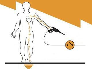
By the beginning of the 80s of the twentieth century. their operation current, based on experiments with volunteers, was chosen to be 30 mA, and small-sized transformers with ferrite ring cores (they are called differential) were created, which became leakage current sensors. Electromechanical differential RCD-DM with a response current of 20 to 30 mA, which are the most popular in everyday life today, have gone on sale. Usually the letters DM are omitted, and the device is simply called an RCD.
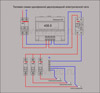
Operating principle of RCD and connection diagram
Currents flowing through the phase and neutral conductors in different directions excite two magnetic fluxes F1 and F2 of equal magnitude in the ring core of the device transformer, however, the magnetic induction vectors corresponding to these fluxes are directed counter-direction in the core and mutually compensate each other. Therefore, the total magnetic flux in the core is zero, as is the EMF in the secondary winding of the transformer. 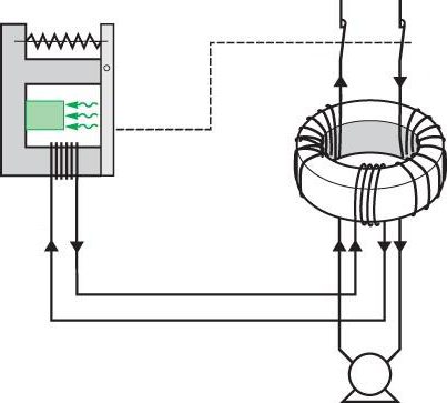
If, due to an insulation defect, a leakage current appears close to the tripping current, then F1 ≠ F2, a magnetic flux appears in the core, inducing an EMF in the output winding, capable of creating a current sufficient to trigger the threshold element of the RCD. Next, the latch of the power contact group is pulled back, and its contacts open. This is the operating principle of all types of RCDs.
All types of such devices have a “Test” button, when pressed, a current leakage situation is artificially created to check the operation of the device. A self-latching flag or button is used to re-enable the RCD after a test operation.
Types of RCD
Known electromechanical and electronic types such protective devices. The principle of operation of the RCD and the connection diagram of both types are the same, however, devices of the first type do not require power supply and have a simple and reliable design. To trigger them, there is enough leakage current in the protected electrical appliance.
An electronic RCD requires supply voltage to be supplied to it, since the threshold element in it is made in the form electronic circuit, which amplifies the small current in the output winding of its transformer and creates an impulse for the executive relay. 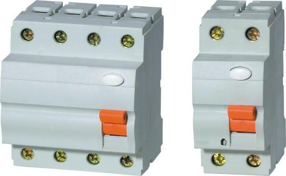
In this regard, the electronic RCD transformer itself is smaller in size, dimensions and power. The threshold element module with an amplifier is powered by a controlled circuit, and if a conductor breaks in its power supply circuit, then such a device will lose its functionality. There are other risks when operating electronic RCDs. For example, failure of its electronic components due to pulse overvoltages in the supply network.
Since the reliability of electronic RCDs is lower than that of electromechanical ones, their cost is also lower.
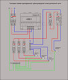
Three-phase RCD
A three-phase device, unlike a single-phase one, has four poles instead of two, since the neutral conductor passes through both types of devices. The operating principle of a three-phase RCD is the same as that of a single-phase one. 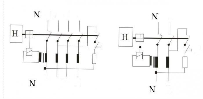
The core of its transformer covers four conductors - three phase and one neutral. The total current in three phase wires (the so-called zero-sequence current) is always equal in magnitude to the current in neutral wire and opposite to it in direction (inside the RCD). In this case, the transformer core is not magnetized, and there is no current in its output winding. If a leakage current appears in the protected device, then an alternating magnetic flux appears in the core, inducing an EMF in the output winding of the transformer. A current proportional to the leakage current begins to flow through it, and if the leakage current exceeds the operation current, the RCD turns off the electrical appliance. The balance of currents in the control body of the RCD is disturbed and it trips.
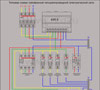
Three-phase RCD without neutral conductor
To protect against leakage currents of asynchronous electric motors, the windings of which are connected in a triangle or in a star with an unconnected neutral, a 4-pole RCD with an unoccupied zero terminal is connected. In the absence of leakage currents in the phases of the electric motor, the sum of the currents in the phase wires is very small and is unable to trigger the protection. The appearance of leakage current from phase wires through the motor housing to the ground causes circulation through the RCD transformer of zero-sequence current, to which the electrical apparatus reacts. General principle The operation of the RCD does not change in this case either.
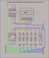
Features of the use of single- and three-phase RCDs
Three-phase 4-pole devices have fairly high operating currents, which allows them to be used only for fire protection, like AVs with thermal releases. Protection of group lines to sockets in rooms, kitchens and bathrooms, or protection of individual power lines of powerful electrical appliances (washing and dishwashers, electric stoves, electric water heaters) should be performed on 2-pole single-phase RCDs with leakage current ratings set from 20 mA to 30 mA. 
In order for the operation of an RCD in a single-phase network to be safe, it itself must be protected from overcurrent (during long-term continuous operation of a working electrical appliance) by an AV installed in front of it with a thermal release.
RCD operation without grounding
As you know, in old Soviet-built houses apartment electrical wiring did not have a separate zero protective conductor, connected to the ground loop. It was assumed that its function was performed by the neutral working conductor (the so-called TN-C power supply system with common neutral working and protective conductors). And since in all editions of the PUE there is a ban on installing protection devices in protective conductors, 2-pole RCDs that simultaneously break both phase and zero are also prohibited. Even the latest 7th current edition of the PUE in clause 7.1.80 confirmed the inadmissibility of installing RCDs in networks according to TN-C system. The fact is that cases of electric shock during their operation have been recorded.
The reason for this was the difference in timing of the device contacts, amounting to a few milliseconds. But if the contact in the neutral wire was disconnected first, then when the insulation broke down on the body of a household electrical appliance, the consumer would be under full phase voltage, so these few milliseconds were quite enough for a fatal injury.
For apartments without neutral protective conductors, it is unacceptable to install a general apartment RCD, but individual such devices can be installed in group socket lines with a common protective conductor or in the power lines of individual electrical appliances, if the protective conductors of socket groups or sockets are connected to their input neutral terminals along the shortest path. 
In this case, a break inside the RCD of the neutral working wire before the phase wire does not lead to a break in the protective conductor of the electrical device, since the section of the protective conductor from the input neutral terminal through the socket and power cord of the electrical device will remain intact.
09.10.2014Single-phase and three-phase electrical network
Electricity reaches the end consumer through power lines, and since they have high voltage, this energy cannot be used without transformation. To reduce voltage, special systems are used - transformer substations; they convert high voltage voltage to the optimal value.
To provide a home with power, a three-phase or single-phase network circuit can be used; their features will be discussed below.
Transformer substation
The transformer substation is designed to receive electricity coming from power lines, convert it and distribute it. The substation includes the following equipment: a step-down transformer, an electricity distribution device (ED) and a control unit.
Outside the city, pole and mast substations are most widespread. The main device of the substation is a single- or three-phase transformer that reduces the voltage. Most often in rural areas a single-phase network circuit is used, operating in conjunction with three-phase transformers.
The voltage is reduced to the nominal level and after conversion can be either 380 V (linear) or 220 V (phase). Accordingly, the power supply received by consumers is called three-phase or single-phase.
Single phase power supply
In order to provide objects with power supply, a single-phase network circuit uses two lines: phase and neutral working wires. Together they form a single-phase electrical network. Rated voltage it is equal to 220 V.
Connecting to a single-phase network using this scheme does not provide for grounding. Nowadays it is used much less frequently - it can be found mainly in buildings that are part of the old housing stock.
Single-phase two-wire network
A single-phase network can be two- or three-wire. One of the signs of a two-wire electrical network is the use of aluminum conductors. In three-wire networks, in addition to the standard wires (phase and neutral), there is also a protective wire that performs the grounding function.
The use of a single-phase network circuit of this type allows for additional protection of home occupants from shock electric shock and avoid burnout electrical appliances. Ground wire (PE) is connected to the housings household appliances, as soon as a phase is shorted to the housing, the equipment turns off.
In the construction of modern buildings, a connection to a single-phase network with three conductors is mainly used, much less often - with one.
Three-phase power supply
Three-phase power involves the introduction of three supply phases into the building, designated L1, L2, L3, and neutral conductor N. The nominal operating voltage between any pairs of phase wires is 380 V, and between the “zero” wire and each of the phase wires is 220 V. Using a three-phase network circuit allows you to supply equipment with electricity at a voltage of 220 or 380 volts. The wiring coming from the electrical panel is laid throughout the home in accordance with the design.
One of the most important tasks when connecting to a three-phase network, carefully calculate the load on each of the three phases, since its uneven distribution can cause phase imbalance. A significant imbalance often leads to emergency situations, including critical ones, when one of the phases burns out. Four- or five-core cables are used to distribute three-phase electricity throughout a facility.
Three-phase network with four-wire cable
To supply electricity to the devices, three phase wires and a working zero are used.
From switchboard two wires are laid to sockets and lighting equipment: a neutral wire in combination with each phase wire. As a result, the devices are provided with electricity having a voltage of 220 V.
The following phase designations are used in the power supply diagram: A, B, C.
Five-wire three-phase electrical network
The fundamental difference between a four-wire power supply and a five-wire power supply is the presence of a ground wire, designated PE. Naturally, connecting to a three-phase network with five conductors provides more high security than when using four conductors.
The greatest difficulty in designing three-phase electrical networks is to evenly distribute the load between the phases. When performing calculations, you should not rely on Ohm’s law - in such cases it is necessary to use the power factor (denoted by cosph) and demand factor - Kdemand. Traditionally, for residential properties cosф is taken to be 0.9-0.93, and the demand coefficient for apartments (if the number of consumers exceeds 5) is taken to be 0.8.
The power sources of modern electrical installations are usually three-phase electrical networks, which are a combination of three voltage sources AC with a frequency of 50 Hz (step-down transformers or generators), the windings of which are connected according to an electric star circuit (Fig. 4.2, a), and power lines.
Common winding output ( common point electric star), called neutral (N) electrical network, and the other three terminals to which the power line conductors are connected are called phases (A, B, C). The alternating current voltages generated by each source of a three-phase network are called phase voltages (UA, UB, UC). They are out of phase with each other by 120 electrical degrees
Rice. 4.2 Voltage system of a three-phase electrical network
Rice. 4.3 General diagram of a three-phase network
(Fig. 4.2, b).
The voltages acting between any pairs of phases of the electrical network are called linear (UAB, UBC, UCA). If the modules are equal phase voltages(|UA| = |UB| = |UC| = Uф) the modules will also be equal line voltages: |UAB|= |UBC| = |UCA| = Ul = Uф. Typically Ul = 380 V, Uph = 220 V.
Power lines in three-phase networks can be overhead or cable type. In both cases, the conductors of the electrical network have some active insulation resistance and capacitance relative to the ground: RA, RB, RC, RN and CA, CB, CC, CN (Fig. 4.3). In the future, in order to simplify the calculations, we will assume that RA = RB = RC = Riz, CA = CB = CC = Cph.

The capacitance of the phase conductor relative to the ground depends on the geometric relationships (suspension height, cross-section, dimensions) and dielectric properties of the insulation.
The complex insulation resistance of each phase of the electrical network relative to ground is determined as the result parallel connection active (Riz) and capacitive (Xph = 1/jwCph) components: Zfrom = Rfrom || Xf = Riz / (1 + jw RizCf). The resistance ZN for the neutral is determined similarly.
The module of the complex insulation resistance of the phase conductor of the electrical network relative to the ground is determined by the formula:  , where w = 2p f – circular frequency of the electrical network;
f = 50 Hz – linear frequency of the electrical network.
By current standards in a network with a voltage of up to 1000 V, the active phase insulation resistance relative to ground in the area between adjacent fuses or behind the last one must have a value of at least 500 kOhm when consumers are disconnected. In a branched electrical network, the number of such parallel-connected sections can be quite large.
The capacitance of the phases relative to the ground is determined by the type of line (aerial, wire, cable), its geometric parameters and cannot be reduced. Particularly large phase capacitance can be in cable lines over a long length, and the magnitude of the complex resistance modulus of phase insulation correspondingly decreases and its protective effect is weakened.
Depending on the neutral mode, there are two most common types of electrical networks:
three-phase network with isolated neutral (INS);
three-phase network with a solidly grounded neutral (SZN).
The neutral in the SIN is well insulated from the ground, so for of this type network we can assume that ZN = | ZN| -> infinity.
The neutral in the SZN is connected to a special grounding device. According to PUE requirements grounding resistance of the trawl R0 at any time of the year should not exceed 4 Ohms for phase voltages of 220 V or for linear voltages of 380 V.
Thus, general scheme a three-phase electrical network can be represented as shown in Fig. 4.3, where to assume ZN-> infinity for the case of SIN And ZN » R0 for the case of SZN .
In a three-phase network there are normal(NR) and emergency(AR) operating modes. Normal mode characterizes good condition electrical network. At emergency mode one of the phases is shorted to ground through a relatively low fault resistance ( Rzm), which characterizes the process of spreading the fault current in the ground at the point of maximum potential (i.e. directly at the point of contact of the current-carrying elements with the ground). Typically, the short circuit resistance is tens or hundreds of ohms and less often - units of ohms, for example, when the wire is shorted to grounded metal structure or falls into a water pool.
Life safety summary