Today, light switches are simply amazing in their variety. In the market you can find a wide range of of this product. After purchasing, you will need to wire the light switch in your home. This process is considered simple if you have some knowledge.
In this article we have provided you with the most detailed information. Here you will learn how to wire a light switch with one, two and three keys. To begin with, you will need to study and understand where these models need to be used.
Today, almost every person knows why a light switch is needed. Typically, a single-key product is used to de-energize one group of lamps. You can install this product in almost any room that has only one group of lamps.
The two-key switch accordingly allows you to operate with two groups of lamps. For example, if your room has main lighting and spotlights, then you can control their operation separately. One key will be responsible for the main lighting, and the second for additional lighting.
A three-key switch is capable of regulating the operation of three groups of light bulbs. This product is usually highly popular in the living room or bedroom.
Now you will learn how to properly connect a switch with one, two or three keys. We have provided you with not only informational, but also photo instructions that can help you complete this process correctly.
Preparatory stages of work
Before connecting the switch, you will need to decide on the tools and installation technology. Here are the main points that will help you accomplish correct installation your design:
- To connect the wires, you can use soldering methods or connect the wire using terminals.
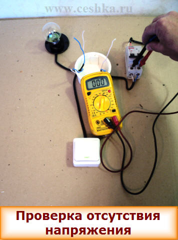
- Before starting work, you will need to turn off the power supply.
- For proper operation switch, only the phase wire must be connected to it, and not the neutral wire. If you make the connection incorrectly, you may get an electric shock.
- Before you connect your device, you need to study color coding wires
- Pliers.
- Electrician's knife.
- Screwdrivers.
- Connectors.
Correct wire routing
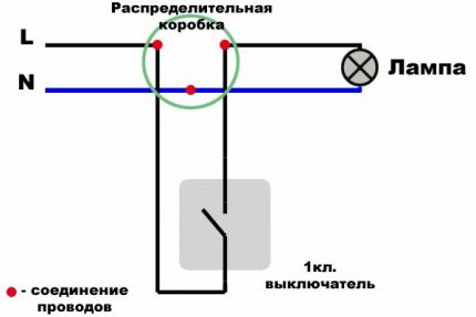
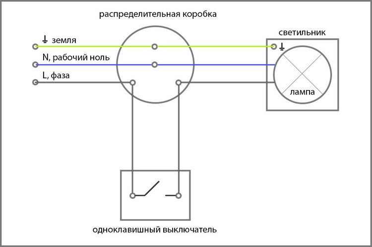
When connecting a switch of any kind, you will need a wiring diagram. The diagram should show the routing of the wire from the junction box to the switch. Now we will look at all connection diagrams. The wires must be routed in a similar manner.
One key
Connecting a single-key switch is quite simple. Even an inexperienced electrician can perform this process.
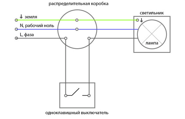
You will need to connect the input zero with the zero on the switch. Usually this wire has Blue colour. The phase wire will first go to your breaker and then it will return to the junction box. Only then will it connect to the lamp. As you can see from the diagrams we have provided you with, this process is not complicated.
Two keys
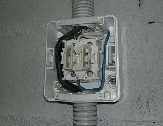
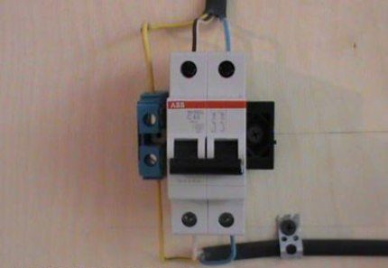
The connection diagram for a two-key switch may be slightly different. This process is primarily due to the fact that circuit breaking will be carried out separately for each key. Here two groups of wires will go into the junction box. When entering the box, you need to connect your blue wire to the other wires.
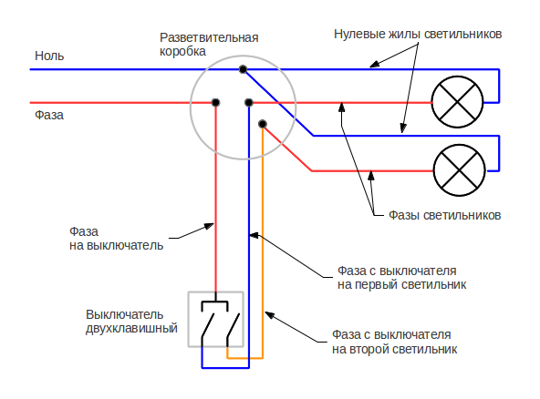
When connecting, the phase will be carried out by breaking the two buttons, and then it will be fixed in a separate hole. The two outgoing wires in this switch will go to each group of lights.
![]()
Three keys
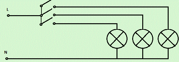
In order to connect a three-key switch you will need certain knowledge. Zero, as in previous cases, you will need to connect in the junction box. The introductory phase should be aimed at breaking. After input, you need to connect the outgoing phases, which will go to three groups of lamps.
How to connect the switch?
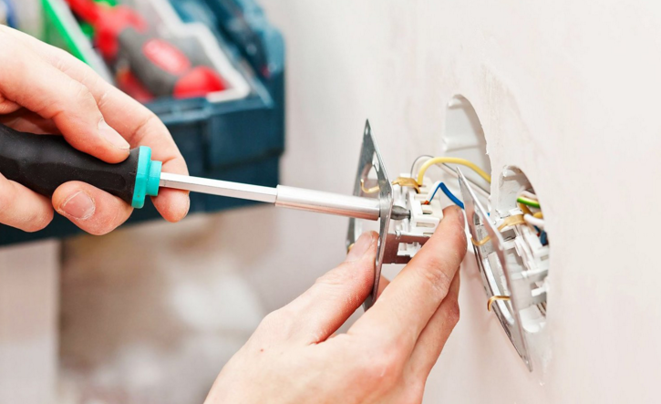
After you have completed all the wire connections in the switch, you will need to install it. Almost anyone can install a switch, and now we’ll talk about it. After you have connected the wires, they must be securely fastened.
Now you can start fixing it in the junction box. It will be secured in the junction box using special clamps. They are located on the sides of this product. First, insert the switch into the socket, and then use a screwdriver to pinch its contacts. After tightening the bolts, the switch will be securely held in the wall.
Once the switch core is securely fastened in the groove, you can begin installing the decorative frame. After decorative frame will be installed, you can start checking the device to see if the device is working. That was it detailed instructions for installing this device. As you can see, almost anyone can connect a switch.
To control household electric lighting sources, various devices are used, the most common of all is the switch. This is a simple device located on the wall and connected to wires. The design of the products is different, but the internal circuit diagram single models are the same. Let's try to figure out how to connect a switch with one key in order to quickly make repairs.
A switch is a simple mechanical (less often electronic) device for contact closing/opening an electrical circuit to turn on/off lighting fixtures.
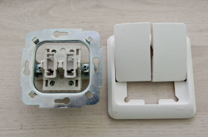
We will touch upon design features and installation of the most simple models– single-key switches. They consist of 4 main parts:
- working unit (metal base with contacts and push-button drive);
- fasteners (metal legs or antennae connected to a metal plate);
- decorative design (panels or frames);
- dynamic part - plastic key.
Some parts, mainly internal, are made of metal (for example, galvanized steel), external decorative finishing usually made of safe plastic. Ceramic elements are also available that can withstand loads of up to 32 A, while plastic is rated for 16 A.
Design simple switch with one key: 1 – the key with which the mechanism is activated; 2 – decorative frame; 3 – working part, which contains the electrical mechanism
The external and internal structure depends on several factors, for example, functional tasks or potential load. As an additional device, some models have an LED that provides external illumination.
Switches are installed in all rooms where there are any lighting devices that are not equipped with a power cable (for example, for floor lamps or table lamps He's not needed). These are most often ceiling or Wall lights, chandeliers, complex lighting systems.
When choosing devices for rooms with increased level humidity, you should pay attention to such an indicator as the level of protection: for a bedroom or living room, IP 20 is enough, for a bathroom or kitchen - IP 40, for outdoor (street) installation - IP 55
Types of devices for household use
There is no strict division into categories, since different manufacturers there are their own, “branded” model series, however, several large categories can be distinguished, united by one characteristic.
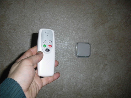
The two most common types modern switches– single-key wall model and a control panel, which is usually supplied with lighting device
For example, according to the principle of inclusion, all devices can be divided into:
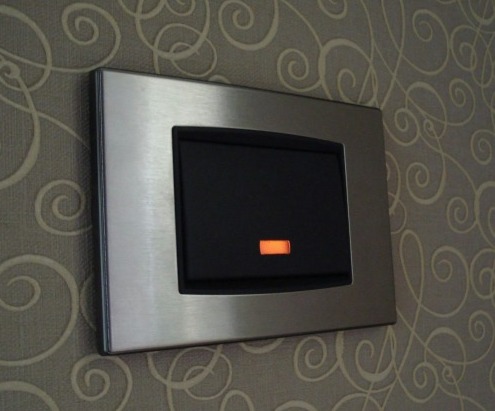
- mechanical - elementary keyboard devices, easy to install and use (the function of a key can be performed by a lever, toggle switch, button, cord, rotary knob);
- electronic touch-sensitive, activated by the touch of a hand;
- With remote control equipped with a remote control or motion sensor.
The first group is considered the most popular, traditional and recognized from the first days of invention electrical circuit, the popularity of the third is also gaining momentum, but the second somehow did not catch on. Motion sensors save energy and serve as additional protection. For example, if you install such a device at the entrance to the house, it will signal the arrival of uninvited guests.
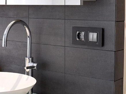
In residential premises, it is preferable to install internal models (with or without lighting), which do not protrude above the wall surface and look more aesthetically pleasing.
According to the type of design, all switches are divided into single-key and multi-key (standard design for household use– with 2-3 keys). Each key serves to close/open one lighting circuit. If there are several lighting fixtures in the room - a chandelier, ceiling lighting and sconces - a three-key switch is appropriate.
According to the installation method, two groups can be distinguished: external and indoor installation. The external type is usually used when the wiring is exposed, and the internal type is used with cables sewn into the wall. To ensure the safety and stability of the installation of the built-in switch, use a mounting box (socket box) - a protective plastic case.
According to the installation method, switches are divided into built-in and surface-mounted. The first ones are used when constructing closed wiring, the second - open. Both options are installed according to similar schemes
Placement: convenience and safety
Before installing the switch, you should consider the most comfortable spot for installation and subsequent use. The most advantageous zone is located around entrance doors(from the side door handle), but there may be exceptions (for example, next to the head of the bed).
Before drawing up a wiring project, it is better to look at the official document - PUE (electrical installation rules), which regulates some of the nuances of installation. For example, clause 7.1.48 states that the switch must be located at least 60 cm from the shower stall, and clause 7.1.50 allows it to be installed no closer than 50 cm from the gas pipeline.
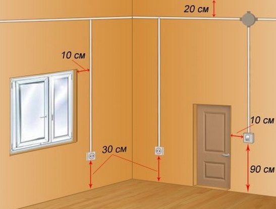
As can be seen from the installation diagram, the distance from the doors to the installation point must be at least 10 cm, and to the floor - at least 90 cm.
The installation of control devices in bathrooms and saunas is prohibited; they must be taken outside the room (usually into the corridor).
Three mounting options for single-key switches
Let's look at three switch connection diagrams that are similar in design (have one button), but differ in the type of installation. Also, all options are united by the basic law of introducing single-key models: the dynamic element opens the “phase” and not the “zero”. Otherwise, there may be a risk of injury during repair work and even when simply replacing lamps.
How to install an outdoor device: detailed photo instructions
The location of the wires for this connection diagram is not of fundamental importance: they can run along the surface or be inside the wall. An external type of switch in a residential area is welcome if expensive repairs have just been made and there is no desire to tear down the walls and install ducts again.
The simplest connection diagram single-key switch, which serves as the basis for practical actions for novice electricians: wire L (phase) goes to the switch, the rest - directly to the light source
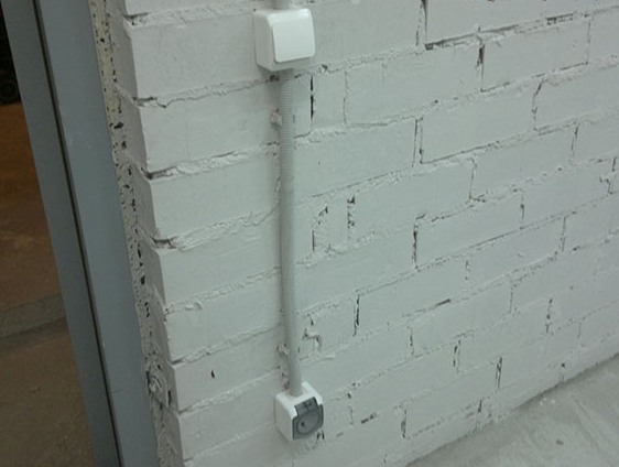
We will consider the option of external cable laying, in which the wires are enclosed in a corrugated protective channel.
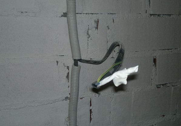
At the installation site of the switch, the corrugated pipe, fixed to the wall with special clips, was cut across, and the worker insulated wire pulled out
There will be another one under the switch electrical appliance– a socket, so the cables for both devices are enclosed in one corrugation for aesthetic reasons.
The power cable associated with the outlet will pass through the surface-mounted switch, so as not to make a loop and not to increase the installation area
The selected switch model - Schneider Electric - has a plastic case and IP44 protection degree. Before installation, we take safety measures: turn off the power to the cable at the electrical panel installed on the site or in the corridor.
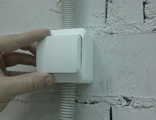
To make sure there is no voltage in the cable, use indicator screwdriver. When the issue of turning off the power is resolved, we begin disassembling the switch. First, we take out the key with our hand - this is done quite easily.

Under the key that closes the switch from above, there is another plastic protective strip - the front panel, which also needs to be removed by carefully pressing out the holders
The next step is to remove the working mechanism.
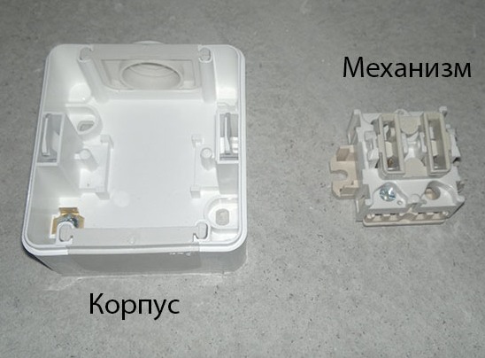
The mechanism that closes/opens the electrical circuit is not secured with special holders or springs, so it can be reached quickly and without problems
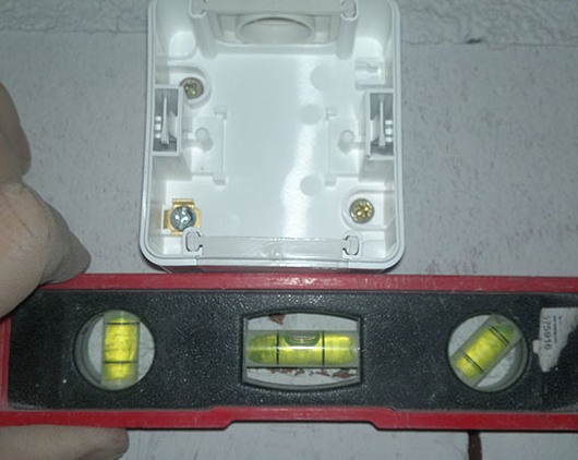
Now you need to accurately determine the location of installation of the switch and mark on the wall the points for screwing in the fasteners. To do this, take an already empty case and attach it to the wall. We level it and use a marker to mark the points for drilling. Using a drill, we drill holes for fastening (another fastening method is also possible).
We fix the plastic case in the designated place on the wall using dowels - the best option fixation on concrete and brick bases
Remove the elastic plug located in the upper part from the switch body, insert the wires into the hole and the end corrugated pipe coming from the ceiling.
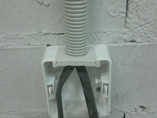
The result should be a neat, tight connection between the corrugation and the body with free access to the wires for further work.
Time to start connecting directly. We remove the insulating material from the ends of the wires and strip 8-10 mm. Connecting the wire white(phase) to the terminal marked L, blue to the other terminal marked “1”. Carefully tighten the bolts and place the working unit into the housing.
We lay the wire leading to the socket around the working unit and bring it out into the lower hole of the housing, and insert the second end of the corrugated pipe there
We reassemble the switch: put it in place front panel, then fix the key.
At the end of the work, we carry out testing: turn on the power supply and press the key several times. If the lighting device lights up when turned on, the connection is correct.
Installing a switch with your own hands is quite easy, even if installation is complicated by the presence additional devices. However, if you are not sure of the correctness of actions, it is better to play it safe and make the first connection under the supervision of an experienced electrician.
Master class on replacing an old switch
Often, in connection with renovations in an apartment or private house, it is necessary to dismantle the old switch and install a new, more modern and convenient one in its place. Let's look at the main replacement steps using step by step photos process.
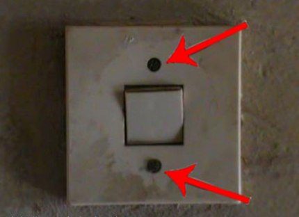
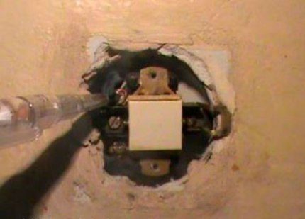
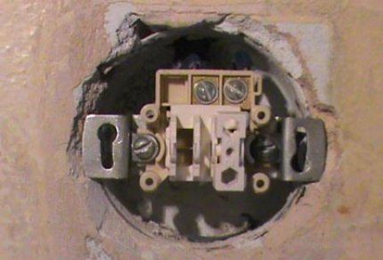
Here is an old, unsightly model of a built-in switch installed inside concrete base panel house. It is necessary to remove it by unscrewing the two mounting bolts
Using a screwdriver, unscrew the screws and remove the plastic cover.
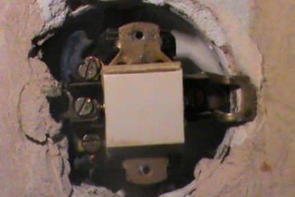
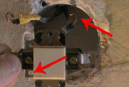
Under the lid - old mechanism connections in which the cores are fixed with a bolted connection. Bolts are visible on the left, and metal fastening “ears” on both sides.
Our task is to determine the “phase”.
To find the working wire, we use a voltage indicator, which is usually an indicator screwdriver with a light signal
We bring the screwdriver to the contacts one by one, never touching them with our hands (it is better to use insulating gloves). For an accurate determination, set the key in both positions. When the “phase” position is off, only one contact will be energized. The second wire is for the lighting fixture.
Having established the purpose of the wires, we turn off the electricity supply, check the presence or absence of voltage and, having made sure that it is safe, we begin to disassemble the old switch. We unscrew the fasteners of the metal holders (“legs”) and take out the working unit.
Carefully disconnect and isolate the wires: first the “phase”, then the second wire. For insulation it is better to use electrical tape different color so as not to make a mistake when connecting
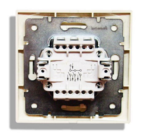
We finally release the mechanism, straighten the wires - the place for the new switch is prepared. We take a new product, purchased in advance, and prepare it for installation, in other words, we disassemble it. We remove the key, unscrew the protective panel and see the internal mechanism - with two mandatory clamps and spacer holders.
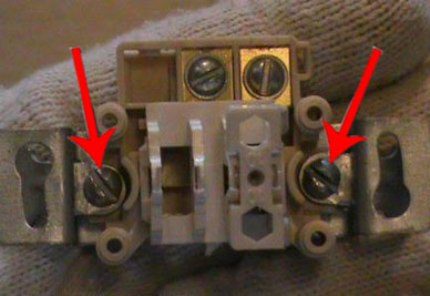
The screws located at the edges regulate the movement of the “legs”, and those located on top are used to connect wires - they are the ones that regulate the contact pressure plate
We strip the ends of the wires about 1 cm, insert them into the holes located under the upper screws, making sure that the winding does not slip inside along with the bare wire. We tighten it tightly so that the wires do not move.
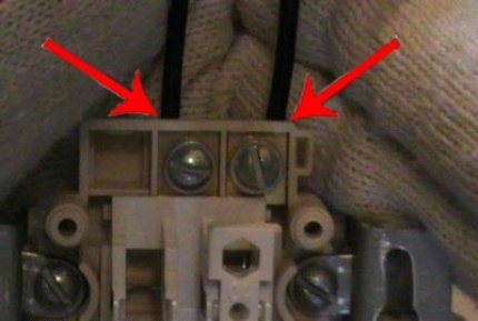
If the holes are marked, insert the “phase” into the hole marked “L”, the outlet wire – “1”. Instead of the indicated designations, there may be numbers “1” and “2” - then the “phase” will go to “1”
Having connected the wires, we insert the working unit into the installation box.
To prevent the mechanism from “walking” inside the socket, we fix it using metal holders, tightly tightening the side fastening screws
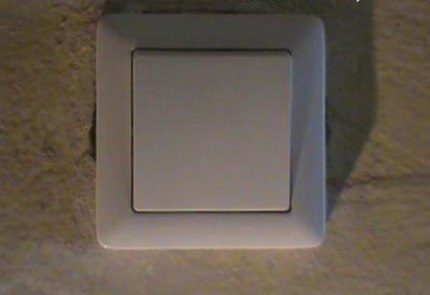
Install the top panel and fix the key.
We test the operation of the device, although it is better to carry out the first check before the internal mechanism is fully secured - so as not to have to redo it
So, to install the new switch we needed tools (screwdriver, pliers, knife, wire cutters, indicator screwdriver), a little insulating material and 20 minutes of time. Calling an electrician would cost about 500 rubles.
Connection diagram with junction box
When you get bare walls (which is common in new modern standard houses), you have to insert it yourself interior doors, lay floors, tidy up walls.
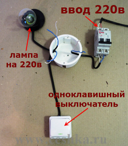
Electrical wiring is no exception. Therefore, let’s consider how to properly connect the switch together with the lighting fixture, circuit breaker and distribution box.
You need to start by choosing a connection diagram. In the picture - the simplest one, with one light source, a single-key switch and an exit to the panel; we will complicate it by installing automation
Our goal is to install all the devices in their designated places and connect them to each other with wires without confusing them. We try to install the distribution box in the center. The open or closed method of cable installation does not fundamentally affect the arrangement of circuit elements.
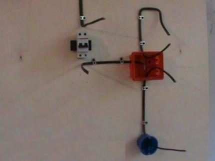
As a result of preliminary installation, you should get the following diagram: automatic block + junction box+ mounting box for switch + light output + three-core cable with cross-section 1.5
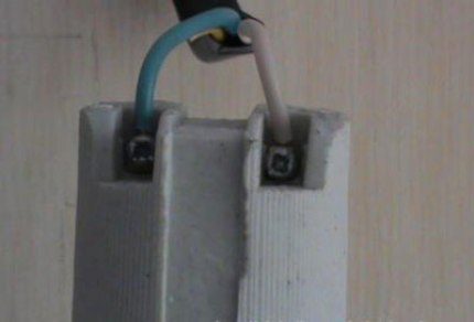
First of all, we connect automatic device protection that protects the network from overloads and power surges. Let's decide on the color of the wires:
- white – “phase”;
- blue – “zero”;
- yellow – “earth”.
We strip the wires and insert them into the terminals intended for them. We use the yellow wire for grounding, fixing it separately with a special clamp.
The role of the lamp will be played by an ordinary socket and a light bulb (incandescent, LED, energy-saving).
We strip the wires and connect them to the socket, inserting them into the holes provided for this purpose. Carefully bend the yellow wire and insulate it
We bring the wires into the installation box to install the switch.
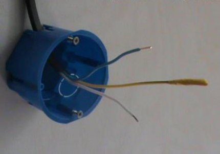
When connecting the switch yellow wire also not useful. We clean the other two, isolate the yellow one and bend it to the side
Modern models of switches have marked terminals, which makes it easier to fix the wiring. We insert them into the required holes and secure them with screws.
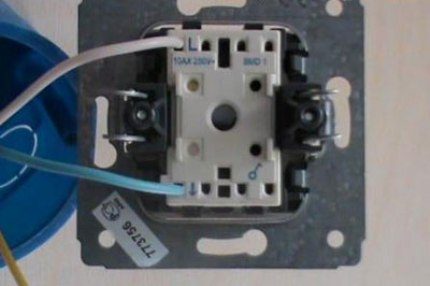
After connecting the wires to the switch mechanism, insert the working unit into the mounting box, put the housing on top, and fix the key
All elements of the circuit are connected, all that remains is to connect the wires in the junction box.
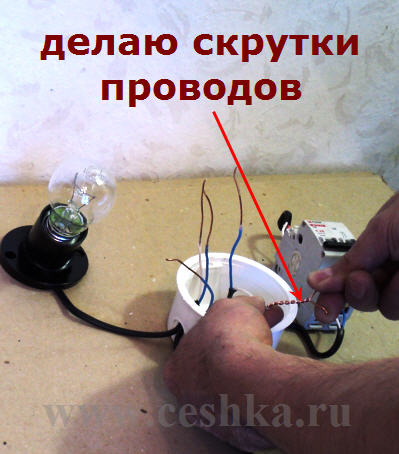
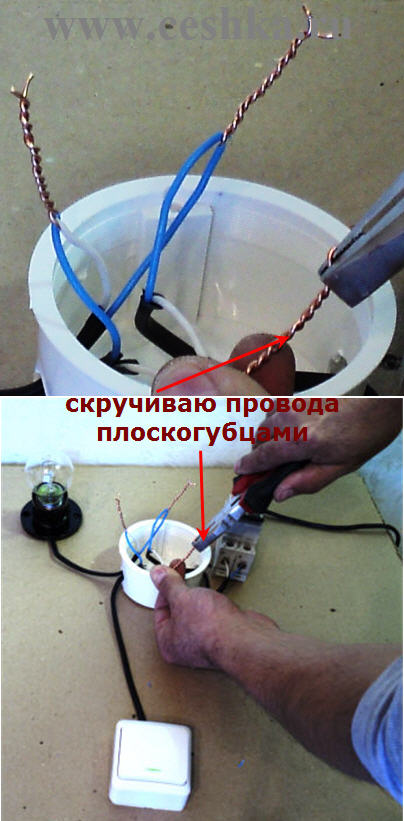
We remove the insulation, strip the ends of the wires, twist them first with our hands, then with pliers. We make the connection according to the colors according to the drawing, remove the uneven ends with pliers
We check the correctness of the connections with an indicator screwdriver and test - press the switch button.
If the light comes on and goes off under the control of the switch, all steps have been completed correctly. After turning off the power, hide the wires and close the junction box
As you can see, you can complete the entire connection diagram yourself using a minimum of simple tools.
Videos with connection examples
Useful video instructions will help novice electricians master the theory and apply it correctly in practice.
Instructions from the legrand manufacturer:
Installation of switch and socket:
Replacing the switch yourself:
As you may have noticed, the principles of connecting various electrical devices similar, but have slight differences. If you decide to replace the switch yourself or install the entire electrical circuit, carefully study the diagrams, consult qualified specialists, and be sure to follow safety precautions during the work.
A single-key switch is the simplest product designed to control home lighting.
From time to time, such products have to be repaired or replaced, so it is advisable to imagine their connection diagram and operating principle.
In our article you will find answers to your questions, a diagram and video recommendations for connecting a single-key switch.
A switch is part of a circuit that includes a source and a consumer of electricity. In this version it is 220 V network and lamp. To turn such a lamp on and off, there must be a disconnecting device between it and the network.
A switch with one key is connected in series to the phase line of the network. In principle, it can be included in the zero line, but this, firstly, will contradict PUE rules, and, secondly, it will be unsafe when servicing electrical devices.
The danger is that when installing the device in the zero line, the energy consumer nodes will be energized even when it is off. And when touching an electrical device, a person may find himself electrocuted.
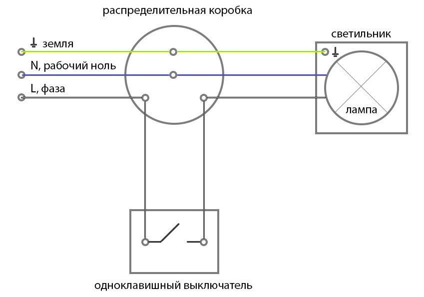
To connect lighting lamp to a network using usually used in which switching is performed. At the same time to her fits 6 electrical lines– two supply voltage, two go to the lamp and two go to the switch.
How to choose the right one
Depending on the type of electrical wiring (or), switches of one or another type may be used in the house. They differ in their design regarding their installation on the wall. In the first case, the device is installed on a wooden plate placed on the wall surface, in the second - in a metal or plastic socket recessed into the wall.
In any case, when choosing a switch, you should pay attention to its limit characteristics. Typically, the operating voltage of a standard device is 220 V, and the operating current is 10 A.
The passport also indicates the maximum switching power (standard -2.2 kW).
At the same time, the power of the consumer, for example, lighting at home, must not exceed this maximum power.
Installation and video instructions
When installing a light control system The greatest attention should be paid to:
- Correct connection of elements in the distribution box (block).
- Correct connection of the switch itself.
Connection diagram for a single-key switch to a light bulb:
To fulfill the first rule, you need to do the following operations:
- Define, suitable with network side. To do this, you can use a probe - with a neon light bulb. If you bring the probe close to the phase, the neon light bulb will begin to glow. If the probe is brought close to zero, then there will be no glow.
- Turn off the power to the apartment.
- Connect the phase to one of the ones going to the switch.
- Connect the second cable coming from the switch to the one that approaches the central contact of the lamp base.
- Connect the wire coming from the external contact of the base to the network zero.
The connection of the stripped ends can be done in various ways:
- twisting and subsequent soldering with further insulation of this place with tape or special caps;
- screw or bolt clamps;
- using terminal blocks;
- spring clamps, for example, Wago type.
The most reliable contact in this case is provided by the first option. Screw and bolted connections are reliable, but when they are performed, damage to the connected elements is possible. Spring clamps can be done very quickly, but over time the springs weaken, leading to sparking and burning.
To execute the second rule, you must perform the following operations:
- Remove the device key using a screwdriver with a thin blade. It should be borne in mind that modern plastic instrument cases have a very fragile structure, so you must act carefully.
- Secure the overhead version of the device with screws on a wooden socket. Use screws to connect the conductors coming from the distribution block to the contacts.
- At hidden wiring at first connect the wires. Then install the housing into the wall niche and secure it with special claws by tightening the fastening screws.
- Reinstall the key.
Learn from this video how to properly connect a single-key light switch:
In the next video we will tell you how to properly install a single-key switch:
In conclusion, you need to turn on the switch and check the operation of the system and its adjustment.
Let's summarize. Single-gang switches are used to control the shutdown of energy-consuming equipment, such as lighting. Such devices are connected to the phase wire in series with the lighting device.
Installation of a system for shutting off devices that use electricity is carried out using a special distribution box.
The device must be selected in such a way that it limit electrical characteristics were equal or more such characteristics of current consumers.
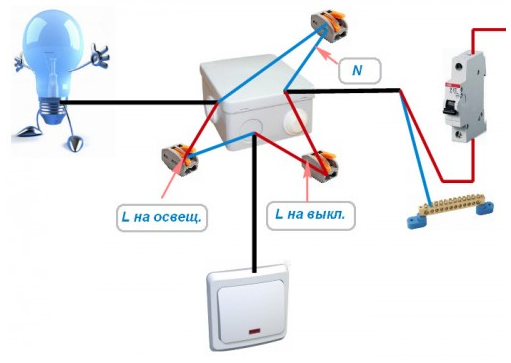
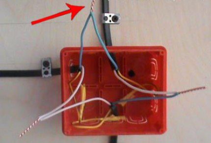
Light switch connection diagram with one key - one of the simplest. I'll explain step by step how to assemble connection diagram .
Look at the photo for yourself, as well as in video tutorial- in total there are three connections in the junction box.
Anyone who has done this knows, it’s just that there is nothing in the box except these wires for the lamp and switch.
But it often happens that in the distribution box there are wires for more than one lamp, and even the sockets are laid right there, then when assembling the circuit you need special care and accuracy.
To make it clear even to the most inexperienced dummies, I recorded a video tutorial.
Switch connection diagram.
If you can’t watch the video, I wrote almost the same thing below. Before starting work, we mean electric installation work, you must make sure that at the place of work no dangerous voltage.
Here I show how to assemble a circuit in a junction box, which means there should be no voltage on the connected wires.
We turn off the machine and check with the device that the voltage has been removed.
Only after this we continue to work.
When connecting a single-key switch in the distribution box, three wires must come in to assemble the circuit:
the first is the power wire, or input wire, which goes to the machine or plugs with a voltage of 220 volts
the second is a wire for the switch, two-wire
the third is the wire for the lamp or lamp.
By the way, many lamps have a grounding clamp on the body, so a three-wire wire-phase, zero and ground.
So, three wires of two wires each go into the distribution box (I don’t count the ground wire from the lamp).
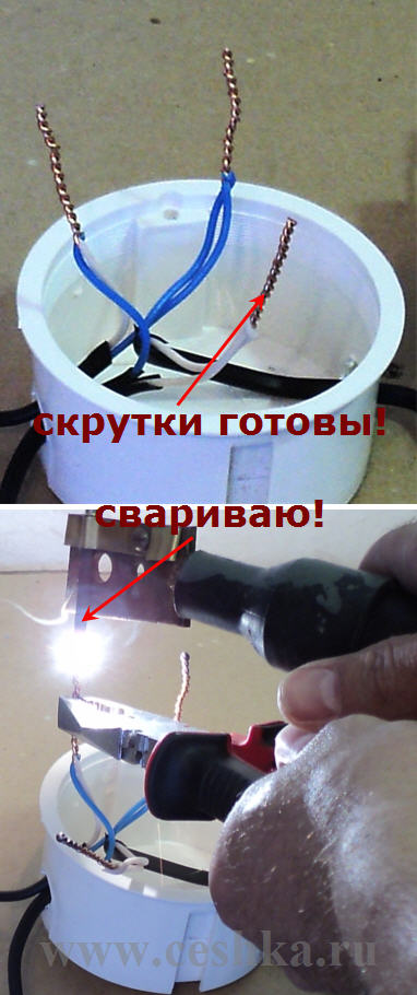
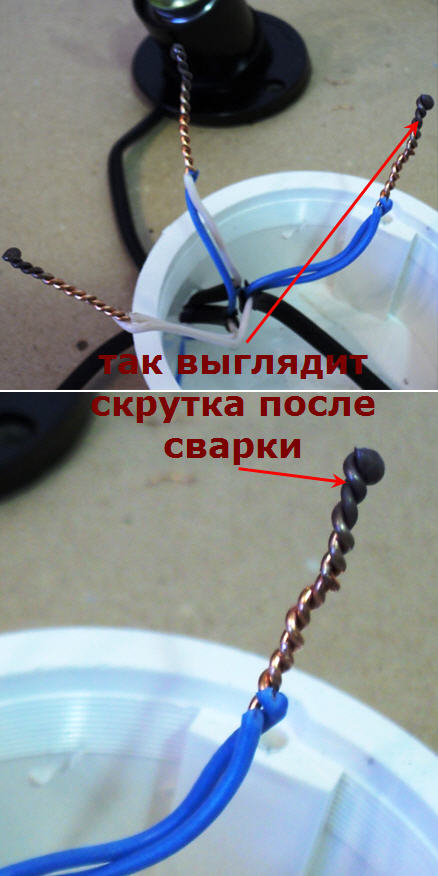
After checking that there is no voltage on the wires, we remove the insulation in order to make a twist.
It is also quite suitable for these purposes, but I am showing it on a twist.
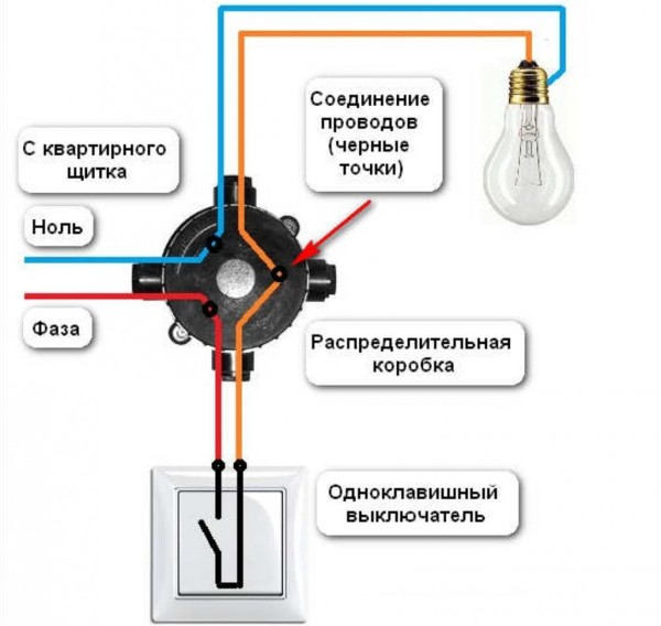
The circuit is assembled like this:
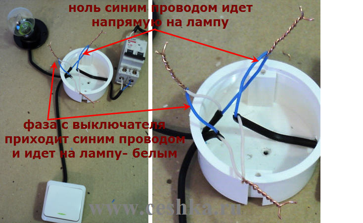
![]() The switch is connected to the phase wire break. The neutral wire goes to the lamp directly, naturally through the junction box.
The switch is connected to the phase wire break. The neutral wire goes to the lamp directly, naturally through the junction box.
The phase through the switch is done so that later, when servicing the lamp - repairing or replacing the lamp, it does not come under voltage.
And it’s just more convenient - turn off the light and calmly change the lamp or lamp.
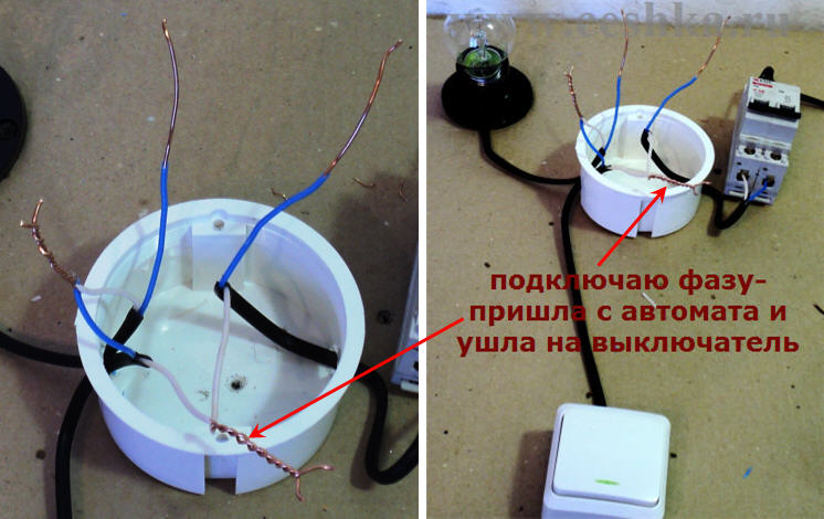
So we find phase wire power that comes to the distribution box from the input and connect it to one of the wires going to the switch.
I always use white or red wire for this.
From the switch, the phase is returned by another wire and connected to the wire going to the lamp.
The remaining wire from the lamp in the junction box is connected to neutral wire nutrition.
 I check the circuit like this: I visually look in the junction box - the phase has arrived and gone to the switch.
From the switch it came into the box and went to the lamp. That's it with the phase.
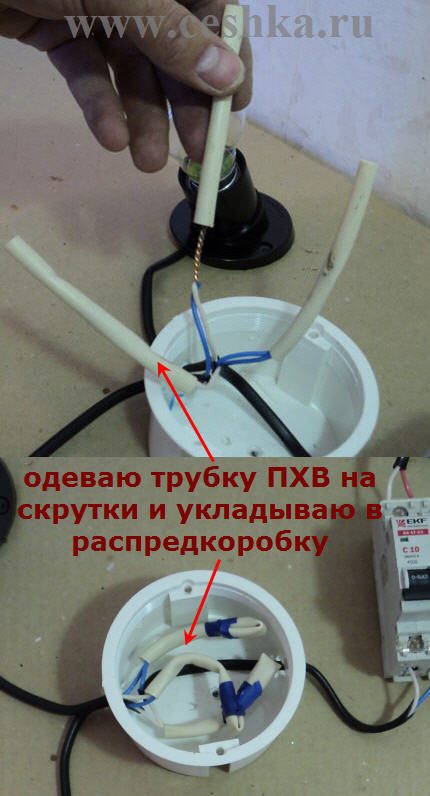
Then I put on the PVC tube and secure it with twists with electrical tape. I carefully place the wires in the junction box and close the lid.
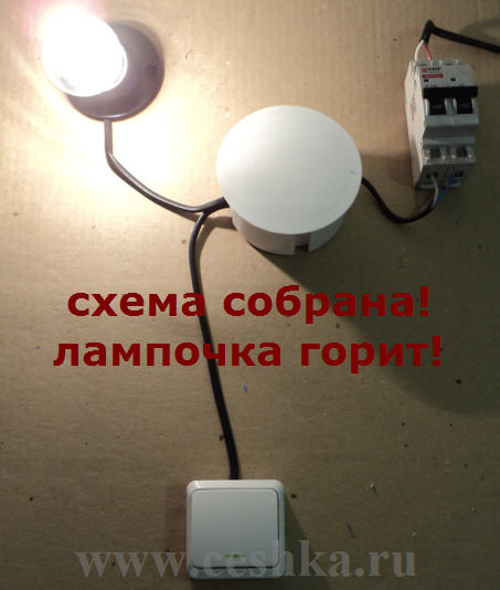
All! This is how it is going switch light with one key.
In the next lesson I will show you how to assemble in practice.
More details on today's topic can be seen in the photographs:
Be the first to know about new site materials!