The connection of elements can be serial, parallel and mixed. Let's calculate the values for all three options. To calculate the values of these quantities, we apply Ohm’s law for a section of the circuit, a well-known law from school: I=U/R; U=I*R; R=U/I.
Simple circuit
Here Ohm's law for a section of a circuit considers the parameters of one consumer (be it a motor or a light bulb), which has resistance R. When electricity meets it, it does work. It is on this barrier that it is created potential difference. Let's take R=10 Ohm as a consumer.
By connecting a 9 V battery to R, we determine the current strength: I=U/R=9/10=0.9 A.
If known R, measuring I, you can find out how much drops across the resistor: I*R=0.9*10=9 B. I*R called voltage drop.
R can be calculated by measuring the volts across it and the amps passing through it. R=U/I=9B/0.9A=10.
It is often necessary to determine the power input R to be sure of its ability to dissipate the heat generated by electricity. Power consumption Р=I 2 *R=0.9 2 A*10=8.1 Wt. It is necessary to select a dissipation power no less than the calculated one, otherwise smoke will come out. In our case, we choose the standard 10 W, the smaller one is only 7.5 W.
Parallel connection
Now let's increase the difficulty of the section. Let's imagine consumers as R1 (10 Ohm) and R2 (5 Ohm). The value of R has changed and two paths have appeared. Only 9 V remained unchanged. 
To calculate the amperes coming to the branches, you need to know the total R. When parallel connection R is calculated using the formula 1/R=1/R1+1/R2+1/Rn... For two elements it looks like this: R=R1*R2/(R1+R2); R=10*5/(10+5)=3.3. Please note: in such a scheme, the resulting R is always less than the smallest.
We find I=9/3.3=2.7 A. The total R is also determined by measuring the total current (measurement showed 2.7 A). Then R=9/2.7=3.3.
Let's calculate each branch separately. All resistors are 9 V. Knowing Rn, we can calculate the amperes of the branch. For the first branch - I1=9V/R1=9/10=0.9 A. For the second - I2=9V/R2=9V/5=1.8. Important detail: the sum of the currents of all branches is equal to the total current. From here, I1=I-I2. The values of R1 and R2 are determined based on the amperes flowing into them and the connected volts: R1=9V/I1 etc.
Now let's see how the law responds to
Serial connection of load.
To find the current in a series circuit, you need to know how many ohms are in it? For a given section R we find this: R=R1+R2; R=10+5=15. We define I=U/R; I=9/15=0.6 A. Now let's take an interest in the voltage drop across the resistors. On R1 - U1=I*R1=0.6*10=6 V.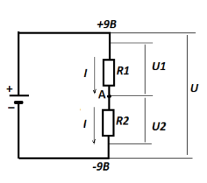
Look: 6 V has dropped on R1, and the total is 9 V. This means that 3 V should remain on R2 (U2=9B-6B=3B). Let's check the law: U2=I*R2=0.6A*5=3 V. That's right.
Along the way, we learned the value of the potential at point A relative to the minus supply - 3 V. This circuit is called voltage divider: from one we get two, and both can be used to power other circuits. Of course, we need to take their input data into account, but that’s for another story, although we also cannot do without Ohm’s law for a section of the circuit.
Mixed load connection
 A mixed connection is a combination of parallel and serial. For calculations, the same algorithm is used that was discussed in the previous versions. You just need to divide the branches according to the appropriate options.
Ohm's law for a section of the circuit follows
Ohm's law for a complete circuit.
It requires inclusion in the calculations of parameters power supply. First, let's look at the features of the device. Rectifier, battery, galvanic cell (ordinary battery), photocell (base solar battery) - present in all sources internal resistance. In the rectifier - the transformer windings and related ones, in the battery - the electrolyte and the degree of emission of the electrodes. 
Ever noticed how battery charging is controlled not by an ordinary voltmeter, but by a load plug? What is this fork for? The battery produces volts, but they are not fully supplied: part ( Ir- read below) falls on his internal barrier. The load fork is something like our studied circuit, which consists of a resistor and a voltmeter connected in parallel. itself is not capable of creating a drop in the internal resistance of the battery. Therefore, a low-resistance shunt is connected in parallel to it, creating Ir. This is how we can judge the completeness of charging. Measuring the charging of the battery only with a voltmeter, we will not get the required result, since the loss in the battery will not be taken into account.
What any generator is capable of producing is called electromotive force (EMF), and what came in electrical network — voltage. The quantities are related as follows: EMF=Ir+IR. r is the internal resistance of the source; the remaining values are already known to us. U got from here: U=EMF-Ir. These two formulas define Ohm's law for complete chain.
§ 2.4. Voltage on a section of the circuit. Under voltage in some area electrical circuit understand the potential difference between the extreme points of this section.
In Fig. 2.5 shows a section of the chain, the extreme points of which are indicated by letters A And b. Let the current I flows from a point A to the point b(from higher potential to lower). Therefore, the potential of the point A(φ a ) above the potential of point b( φ b ) by a value equal to the product of the current I for resistance R: φ a = φ b+ IR.
According to the definition, the voltage between points A And b U ab = φ a - φ b .
Therefore, U ab = IR, i.e. the voltage across the resistance is equal to the product of the current flowing through the resistance and the value of this resistance.
In electrical engineering, the potential difference across the ends of a resistance is called either the voltage across the resistance or the voltage drop. Subsequently, the potential difference at the ends of the resistance, i.e., the product IR, we will call it the voltage drop.
The positive direction of the voltage drop in any section (the direction of reading this voltage), indicated in the figures by an arrow, coincides with the positive direction of reading the current flowing through a given resistance.
In turn, the positive direction of the current count I(current is an algebraic scalar) coincides with the positive direction of the normal to the cross section of the conductor when calculating the current using the formula, where δ is the current density; - element of cross-sectional area (for more details, see § 20.1).
Let's consider the question of voltage in a section of a circuit containing not only resistance, but also emf.

In Fig. 2.6, a, b shows sections of some circuits through which current flows I. Let's find the potential difference (voltage) between the points A And With for these areas. A-priory,
U ac = φ a - φ c (2.1)
Let us express the potential of a point A through the potential of the point With. When moving from a point With to the point b opposite to the direction of the EMF E(Fig. 2.6, a) point potential b turns out to be lower (less) than the potential of the point With, to the EMF value E: φ b = φ c- E. When moving from a point With to the point b according to the direction of the EMF E(Fig. 2.6, b) point potential b turns out to be higher (greater) than the potential of the point With, to the EMF value E: φ b = φ c+ E.
Since in a section of the circuit without an EMF source, the current flows from a higher potential to a lower one, in both circuits Fig. 2.6 point potential A above point potential b to the value of the voltage drop across the resistance R: φ a = φ b+ IR. Thus, for Fig. 2.6, a
φ a = φ c- E+IR ,
U ac = φ a - φ c= IR - E , (2.2)
for fig. 2.6, b
φ a = φ c+ E + IR ,
U ac = φ a - φ c= IR + E. (2.2a)
Positive voltage direction U ac indicated by an arrow from A To With. According to the definition, U ca = φ c - φ a , That's why U ca= - U ac ,T. That is, a change in the alternation (sequence) of indices is equivalent to a change in the sign of this voltage. Therefore, voltage can be both positive and negative.
Hello, dear readers of the Electrician's Notes website..
Today I’m opening a new section on the site called.
In this section I will try to explain electrical engineering issues to you in a clear and simple manner. I will say right away that it is far to delve into theoretical knowledge We won’t, but we’ll get to know the basics in good order.
The first thing I want to introduce you to is Ohm's law for a section of a chain. This is the most basic law that everyone should know.
Knowledge of this law will allow us to easily and accurately determine the values of current, voltage (potential difference) and resistance in a section of the circuit.
Who is Om? A little history
Ohm's law was discovered by the famous German physicist Georg Simon Ohm in 1826. This is what he looked like.

I will not tell you the entire biography of Georg Ohm. You can find out more about this on other resources.
I will only say the most important things.
The most basic law of electrical engineering is named after him, which we actively use in complex calculations in design, in production and in everyday life.
Ohm's law for a homogeneous section of a chain is as follows:

I – the value of the current flowing through a section of the circuit (measured in amperes)
U – voltage value on a section of the circuit (measured in volts)
R – resistance value of the circuit section (measured in Ohms)
If the formula is explained in words, it turns out that the current strength is proportional to the voltage and inversely proportional to the resistance of the circuit section.
Let's conduct an experiment
To understand the formula not in words, but in deeds, you need to assemble the following diagram:
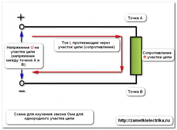
The purpose of this article is to show clearly how to use Ohm's law for a section of a circuit. Therefore, I assembled this circuit on my workbench. See below what she looks like.

Using the control (selection) key, you can select either constant voltage or AC voltage at the exit. In our case, constant voltage is used. I change the voltage level using a laboratory autotransformer (LATR).

In our experiment, I will use a voltage across a section of the circuit equal to 220 (V). We check the output voltage using a voltmeter.

Now we are completely ready to conduct our own experiment and test Ohm’s law in reality.
Below I will give 3 examples. In each example, we will determine the required value using 2 methods: using a formula and in a practical way.
Example #1
In the first example, we need to find the current (I) in the circuit, knowing the magnitude of the source DC voltage and resistance value LED light bulb.
The DC voltage source voltage is U = 220 (V). The resistance of an LED light bulb is R = 40740 (Ohm).
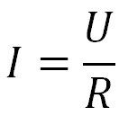
Using the formula, we find the current in the circuit:

I = U/R = 220 / 40740 = 0.0054 (A)
We connect in series with the LED light bulb, switched on in ammeter mode, and measure the current in the circuit.
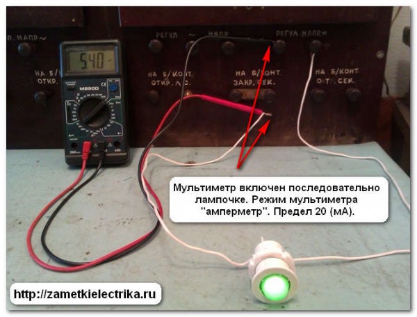
The multimeter display shows the circuit current. Its value is 5.4 (mA) or 0.0054 (A), which corresponds to the current found by the formula.
Example No. 2
In the second example, we need to find the voltage (U) of a section of the circuit, knowing the amount of current in the circuit and the resistance value of the LED light bulb.
I = 0.0054 (A)
R = 40740 (Ohm)
Using the formula, we find the voltage of the circuit section:

U = I*R = 0.0054 *40740 = 219.9 (V) = 220 (V)
Now let’s check the result obtained in a practical way.
We connect a multimeter turned on in voltmeter mode in parallel with the LED light bulb and measure the voltage.
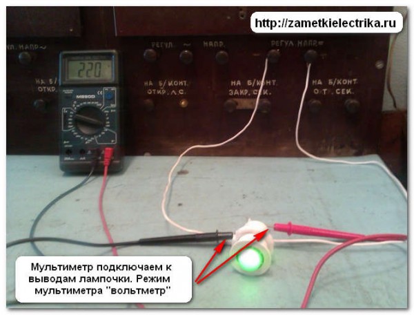
The multimeter display shows the measured voltage. Its value is 220 (V), which corresponds to the voltage found using the Ohm's law formula for a section of the circuit.
Example No. 3
In the third example, we need to find the resistance (R) of a circuit section, knowing the magnitude of the current in the circuit and the voltage value of the circuit section.
I = 0.0054 (A)
U = 220 (V)
Again, let's use the formula and find the resistance of the circuit section:
R = U/I = 220/0.0054 = 40740.7 (Ohm)
Now let’s check the result obtained in a practical way.
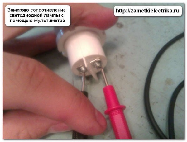
We measure the resistance of an LED light bulb using a multimeter.
The resulting value was R = 40740 (Ohm), which corresponds to the resistance found by the formula.
How easy it is to remember Ohm's Law for a section of a circuit!!!
In order not to get confused and to easily remember the formula, you can use a small hint that you can do yourself.
Draw a triangle and enter the parameters of the electrical circuit into it, according to the figure below. You should get it like this.

How to use it?
Using the hint triangle is very easy and simple. Close with your finger the circuit parameter that needs to be found.
If the remaining parameters on the triangle are located at the same level, then they need to be multiplied.
If the remaining parameters on the triangle are located at at different levels, then it is necessary to divide the upper parameter by the lower one.
With the help of a hint triangle, you will not get confused in the formula. But it’s better to learn it like the multiplication table.
conclusions
At the end of the article I will draw a conclusion.
Electric current is a directed flow of electrons from point B with a minus potential to point A with a plus potential. And the higher the potential difference between these points, the more electrons will move from point B to point A, i.e. The current in the circuit will increase, provided that the circuit resistance remains unchanged.
But the resistance of the light bulb opposes the flow of electric current. And what more resistance in the chain ( serial connection several light bulbs), the lower the current in the circuit will be, at a constant mains voltage.
P.S. Here on the Internet I found a funny but explanatory cartoon on the topic of Ohm’s law for a section of a circuit.

Georg Simon Ohm began his research inspired by the famous work of Jean Baptiste Fourier, “The Analytical Theory of Heat.” In this work, Fourier represented the heat flow between two points as a temperature difference, and the change heat flow associated with his passage through an obstacle irregular shape made of heat-insulating material. Similarly, Ohm caused the occurrence of electric current by a potential difference.
Based on this, Om began to experiment with different materials conductor. In order to determine their conductivity, he connected them in series and adjusted their length so that the current was the same in all cases.
It was important for such measurements to select conductors of the same diameter. Ohm, measuring the conductivity of silver and gold, obtained results that, according to modern data, are not accurate. Thus, Ohm's silver conductor conducted less electric current than gold. Om himself explained this by saying that his silver conductor was coated with oil and because of this, apparently, the experiment did not give accurate results.
However, this was not the only problem that physicists who at that time were engaged in similar experiments with electricity had problems with. Great difficulties in obtaining pure materials without impurities for experiments and difficulties in calibrating the diameter of the conductor distorted the test results. An even bigger snag was that the current strength was constantly changing during the tests, since the current source was variable chemical elements. Under such conditions, Ohm derived a logarithmic dependence of the current on the resistance of the wire.
A little later, the German physicist Poggendorff, who specialized in electrochemistry, suggested that Ohm replace the chemical elements with a thermocouple made of bismuth and copper. Om began his experiments again. This time he used a thermoelectric device powered by the Seebeck effect as a battery. To it he connected in series 8 copper conductors of the same diameter, but of different lengths. To measure the current, Ohm suspended a magnetic needle over the conductors using a metal thread. The current running parallel to this arrow shifted it to the side. When this happened, the physicist twisted the thread until the arrow returned to its original position. Based on the angle at which the thread was twisted, one could judge the value of the current.
As a result of a new experiment, Ohm came to the formula:
X = a / b + l
Here X– intensity magnetic field wires, l– wire length, a– constant source voltage, b – resistance constant the remaining elements of the chain.
If you turn to modern terms to describe this formula, we get that X– current strength, A – EMF source, b + l – total resistance chains.
Ohm's law for a section of a circuit
Ohm's law for a separate section of a circuit states: the current strength in a section of a circuit increases as the voltage increases and decreases as the resistance of this section increases.
I=U/R
Based on this formula, we can decide that the resistance of the conductor depends on the potential difference. From a mathematical point of view, this is correct, but from a physics point of view, it is false. This formula is applicable only for calculating the resistance on a separate section of the circuit.
Thus, the formula for calculating the conductor resistance will take the form:
R = p ⋅ l / s
Ohm's law for a complete circuit
The difference between Ohm's law for a complete circuit and Ohm's law for a section of a circuit is that now we must take into account two types of resistance. This is “R” the resistance of all components of the system and “r” the internal resistance of the source of electromotive force. The formula thus takes the form:
I = U / R + r
Ohm's law for alternating current
Alternating current differs from direct current in that it changes over certain time periods. Specifically, it changes its meaning and direction. To apply Ohm's law here, you need to take into account that the resistance in the circuit with DC may differ from the resistance in a circuit with alternating current. And it differs if components with reactance are used in the circuit. Reactance can be inductive (coils, transformers, chokes) or capacitive (capacitor).
Let's try to figure out what the real difference is between reactive and active resistance in a circuit with alternating current. You should already understand that the value of voltage and current in such a circuit changes over time and, roughly speaking, have a wave form.
If we diagram how these two values change over time, we get a sine wave. Both voltage and current rise from zero to a maximum value, then, falling, pass through zero and reach a maximum negative value. After this, they rise again through zero to the maximum value and so on. When it is said that current or voltage is negative, it means that it moves in the opposite direction.
The whole process occurs with a certain frequency. The point where the voltage or current value from the minimum value rising to the maximum value passes through zero is called phase.
In fact, this is just a preface. Let's return to reactive and active resistance. The difference is that in a circuit with active resistance, the current phase coincides with the voltage phase. That is, both the current value and the voltage value reach a maximum in one direction at the same time. In this case, our formula for calculating voltage, resistance or current does not change.
If the circuit contains reactance, the phases of the current and voltage shift from each other by ¼ of a period. This means that when the current reaches its maximum value, the voltage will be zero and vice versa. When inductive reactance is applied, the voltage phase "overtakes" the current phase. When capacitance is applied, the current phase "overtakes" the voltage phase.
Formula for calculating the voltage drop across inductive reactance:
U = I ⋅ ωL
Where L is the inductance of the reactance, and ω – angular frequency (time derivative of the oscillation phase).
Formula for calculating the voltage drop across capacitance:
U = I / ω ⋅ C
WITH– reactance capacitance.
These two formulas are special cases of Ohm's law for variable circuits.
The complete one will look like this:
I=U/Z
Here Z– total resistance variable circuit known as impedance.
Scope of application
Ohm's law is not a basic law in physics, it is just a convenient dependence of some values on others, which is suitable in almost any practical situation. Therefore, it will be easier to list situations when the law may not work:
- If there is inertia of charge carriers, for example in some high-frequency electric fields;
- In superconductors;
- If the wire heats up to such an extent that the current-voltage characteristic ceases to be linear. For example, in incandescent lamps;
- In vacuum and gas radio tubes;
- In diodes and transistors.
This is the volume of water in a certain period of time.
Now let's consider such a case. Instead of a tower, we will have a vessel with water in which three identical holes are punched at different heights of the vessel. Since our vessel is filled with water, therefore, at the bottom of the vessel the pressure will be greater than on its surface. Or, by analogy with electricity, the voltage at the bottom will be greater than at its surface.
As you can see, the bottom jet, which is closer to the bottom, shoots further than the middle jet. And the middle jet shoots further than the top one. Please note that the holes are the same diameter everywhere. That is, we can say that the resistance of each hole to water is the same. In the same amount of time, the volume of water flowing out from the lowest hole is much greater than the volume of water flowing out from the middle and uppermost hole. What is the volume of water we have over a period of time? Yes, this is the current strength!
So, what pattern do we see here? Considering that the resistance is the same everywhere, it turns out that As the voltage increases, so does the current!
I think each of you has garden plot, where you grow potatoes, cucumbers and tomatoes. There is always somewhere close to you water tower

What is a water tower for? Well, to control the level of water consumption, as well as to create pressure in the pipes through which water comes to your garden plot. Have you ever noticed that a tower is built somewhere on a hill? Why is this being done? To create pressure. Well, let's say that your garden plot is higher than the top of the water tower. Yes, the water simply won’t reach you! Physics... the law of communicating vessels.
Okay, we seem to have gotten distracted.
Everyone in the kitchen and bathroom has a faucet through which water flows. You decide to wash your hands. To do this, you turn on the water at full speed, and it begins to flow in a rapid stream from the tap:

But you are not satisfied with this flow of water, so by turning the tap handle, you reduce the flow:

What just happened?
By changing the flow resistance using the faucet handle, you ensured that the flow of water began to flow very weakly.
Let's draw an analogy to this situation with electric shock. So what do we have? We did not change the flow voltage. Somewhere in the distance there is a water tower and creates pressure in the pipes. We don’t have the right to touch the water tower, much less demolish it). Therefore, our voltage is constant and does not change. By screwing back the faucet handle, we have just changed the resistance of the pipe from which the faucet is made ;-). We increased the resistance. What did we do with the flow of water? She began to run slower and there were fewer of her! That is, we can say that the number of water molecules over a period of time with the faucet fully open and half-closed turned out to be different ;-). Well, let’s remember what current strength is ;-) For those who forgot, let me remind you - this is the number of electrons flowing through the cross section of a conductor over a certain period of time. And what happened to this current strength? She has shrunk!
We conclude:
As resistance increases, current decreases.
So. We have the following water supply scheme:

Now imagine that you are watering the garden and you you need to fill a bucket with water from a hose in 10 minutes. Not a second earlier and not later! In your garden, the flow of water runs something like this:

Let's say we have a simple rubber hose coming from the water tower.A neighbor accidentally parked his car right on the hose and slightly pressed it down
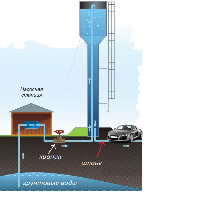
Your water flow has begun to decrease. Go argue with your neighbor? He has already left on business, and you won’t have time to fill the bucket in 10 minutes. It will take more time. How to be? Why don't we open the faucet in front of the water tower a little bigger? And this good idea! We open the faucet to the fullest and make sure that the water level in the tower becomes higher than it was before (although the towers have protection against overflow of any maximum level, but for the sake of the example we will skip this point).
But trouble does not come alone. The water pump control relay on the tower is broken! The pump pumps water and does not turn off! The tower is overflowing and the flow of water from the hose is becoming larger and larger every second! What to do? We will fill our bucket in the time allotted to us! Relax. There is an exit! To do this, we run and turn off the faucet a little, ensuring that the flow of water from the hose flows as before;-).
Now let's make an analogy.
So what do we get? The neighbor crushed the hose, which means increased resistance. Therefore, our current strength has become less. To restore the current strength, we increased the voltage, that is, the water level in the tower.
Second point:
The water level (voltage) at the water tower began to increase due to the fact that the pump did not turn off and pumped water all the time. Therefore, our water flow (current strength) also began to increase. To equalize the current strength, we increased resistance faucet ;-), thereby bringing the water level in the water tower (voltage) back to normal.
Well, did you see the pattern? But the German physicist Georg Ohm connected these three quantities with each other and the result was a painfully simple formula:
Where
I- this is the current strength, expressed in Amperes (A)
U- voltage, expressed in Volts (V)
R- resistance, expressed in Ohms (Ohm)
Well, it’s as simple as two and two, isn’t it? This law is named after its discoverer and is called Ohm's law. This is the most important law in electronics, and therefore you MUST know it.