In a uniform magnetic field, a straight conductor moves at a constant speed so that the velocity vector is perpendicular to the conductor. Induction vector magnetic field is also perpendicular to the conductor and makes an angle α = 30° with the vector. Then the same conductor begins to move at the same speed, in the same magnetic field, but in such a way that the angle α increases by 2 times. How will the following change as a result? physical quantities: module of the induced emf arising in the conductor; modulus of the electric field strength inside the conductor?
For each quantity, determine the corresponding nature of the change:
1) will increase;
2) will decrease;
3) will not change.
Write down the numbers in your answer, arranging them in the order corresponding to the table:
Solution.
The induced emf for a conductor moving in a magnetic field perpendicular to the conductor is calculated by the formula: Therefore, as the angle between the speed and direction of the magnetic field increases, the induced emf in the conductor will also increase.
The modulus of the electric field strength inside the conductor is directly proportional to the induced emf, therefore, the modulus of the electric field strength will also increase.
Answer: 11.
Answer: 11
Source: StatGrad: Training work in physics 04/29/2016 Option PH10503
Yulia Gorbacheva 14.04.2017 22:26
In the reference frame of the conductor (where it is stationary), a constant electric field arises. If the conductor is in constant electric field, then the magnitude of the electric field inside it is zero.
You can argue differently. If there is an electric field strength inside a conductor, then a force acts on the charge carriers in the conductor (for example, electrons). Under the influence of this force, charge carriers move and an electric current exists in the conductor. Thus, the very statement that there is a non-zero electric field strength inside a conductor is equivalent to the statement that a constant current is maintained in the conductor.
Availability direct current in a conductor that does not form a closed circuit - this is an absurdity, contrary to the law of conservation of charge.
Anton
The charges in the conductor under consideration are acted upon by two forces that balance each other: the force from the electric field created by the redistributed charges (during the transition process at the beginning of the movement), and the Lorentz force from the magnetic field. If there were no electric field, the magnetic field would cause an electric current. During the transition process, this electric current leads to a redistribution of charges in the conductor.
When the electric field strength is different from zero, a current arises in the conductor if there are no external forces that can increase or decrease this current, including completely compensating the effect of the electric field.
The direction of magnetic field lines can be determined using the gimlet rule. If the forward movement of the gimlet (Fig. 27) align with the direction of the current in the conductor, then rotation of its handle will indicate the direction of the magnetic field lines around the conductor. The greater the current passing through the conductor, the stronger the magnetic field that arises around it. When the direction of the current changes, the magnetic field also changes its direction.
As you move away from the conductor, magnetic power lines are located less frequently.
Methods of strengthening magnetic fields. To obtain strong magnetic fields at low currents, they usually increase the number of current-carrying conductors and make them in the form of a series of turns; such a device is called a coil.
With a conductor bent in the form of a coil (Fig. 28, a), the magnetic fields formed by all sections of this conductor will have the same direction inside the coil. Therefore, the intensity of the magnetic field inside the coil will be greater than around a straight conductor. When the turns are combined into a coil, the magnetic fields 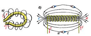 created by individual turns, add up (Fig. 28, b) and their lines of force are connected into a common magnetic flux. In this case, the concentration of field lines inside the coil increases, i.e., the magnetic field inside it intensifies. The greater the current passing through the coil, and the more turns there are in it, the stronger the magnetic field created by the coil.
A coil flowing with current is an artificial electric magnet. To enhance the magnetic field, a steel core is inserted inside the coil; such a device is called an electromagnet.
18. Magnetic properties of various substances.
All substances, depending on their magnetic properties, are divided into three groups: ferromagnetic, paramagnetic and diamagnetic.
Ferromagnetic materials include iron, cobalt, nickel and their alloys. They have high magnetic permeability µ They are well attracted to magnets and electromagnets.
Paramagnetic materials include aluminum, tin, chromium, manganese, platinum, tungsten, solutions of iron salts, etc. Paramagnetic materials are attracted to magnets and electromagnets many times weaker than ferromagnetic materials.
Diamagnetic materials are not attracted to magnets, but, on the contrary, are repelled. These include copper, silver, gold, lead, zinc, resin, water, most gases, air, etc.
Magnetic properties of ferromagnetic materials. Ferromagnetic materials, due to their ability to be magnetized, are widely used in the manufacture of electrical machines, devices and other electrical installations.
Magnetization curve. The process of magnetization of a ferromagnetic material can be depicted in the form of a magnetization curve (Fig. 31), which represents the dependence of induction IN from tension N magnetic field (from magnetizing current I ).
The magnetization curve can be divided into three sections: Ooh
, at which the magnetic induction increases almost proportionally to the magnetizing current; a-b
, at which the growth of magnetic induction slows down, and the area of magnetic saturation beyond the point b
, Where 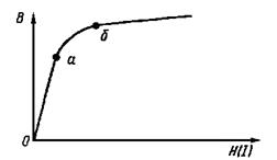 addiction IN
from N
becomes linear again, but is characterized by a slow increase in magnetic induction with increasing field strength.
addiction IN
from N
becomes linear again, but is characterized by a slow increase in magnetic induction with increasing field strength.
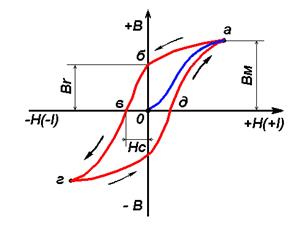 Magnetization reversal of ferromagnetic materials, hysteresis loop. Big practical significance, especially in electric machines and installations alternating current, has a process of magnetization reversal of ferromagnetic materials. In Fig. Figure 32 shows a graph of changes in induction during magnetization and demagnetization of a ferromagnetic material (with a change in the magnetizing current I
. As can be seen from this graph, at the same values of magnetic field strength, the magnetic induction obtained by demagnetizing a ferromagnetic body (section a B C
), there will be more induction obtained during magnetization (sections Ooh
And Yes
). When the magnetizing current is brought to zero, the induction in the ferromagnetic material will not decrease to zero, but will retain a certain value In r
, corresponding to the segment About
. This value is called residual induction.
Magnetization reversal of ferromagnetic materials, hysteresis loop. Big practical significance, especially in electric machines and installations alternating current, has a process of magnetization reversal of ferromagnetic materials. In Fig. Figure 32 shows a graph of changes in induction during magnetization and demagnetization of a ferromagnetic material (with a change in the magnetizing current I
. As can be seen from this graph, at the same values of magnetic field strength, the magnetic induction obtained by demagnetizing a ferromagnetic body (section a B C
), there will be more induction obtained during magnetization (sections Ooh
And Yes
). When the magnetizing current is brought to zero, the induction in the ferromagnetic material will not decrease to zero, but will retain a certain value In r
, corresponding to the segment About
. This value is called residual induction.
The phenomenon of lag, or delay, in changes in magnetic induction from corresponding changes in magnetic field strength is called magnetic hysteresis, and the preservation of a magnetic field in a ferromagnetic material after the magnetizing current has stopped flowing is called magnetic hysteresis. residual magnetism.
 By changing the direction of the magnetizing current, you can completely demagnetize the ferromagnetic body and bring the magnetic induction in it to zero. Reverse tension N s
, at which the induction in a ferromagnetic material decreases to zero is called coercive force.
curve Ooh
, obtained under the condition that the ferromagnetic substance has been previously demagnetized, is called the initial magnetization curve. The induction change curve is called hysteresis loop.
By changing the direction of the magnetizing current, you can completely demagnetize the ferromagnetic body and bring the magnetic induction in it to zero. Reverse tension N s
, at which the induction in a ferromagnetic material decreases to zero is called coercive force.
curve Ooh
, obtained under the condition that the ferromagnetic substance has been previously demagnetized, is called the initial magnetization curve. The induction change curve is called hysteresis loop.
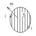
The influence of ferromagnetic materials on the magnetic field distribution. If you place any body made of ferromagnetic material in a magnetic field, then the magnetic lines of force will enter and exit it at right angles. In the body itself and near it, there will be a condensation of the field lines, i.e., the magnetic field induction inside the body and near it increases. If you make a ferromagnetic body in the form of a ring, then magnetic field lines will practically not penetrate into its internal cavity (Fig. 33) and the ring will serve as a magnetic shield protecting the internal cavity from the influence of the magnetic field. The action is based on this property of ferromagnetic materials different screens protecting electrical measuring instruments, electrical cables and other electrical devices from the harmful effects of external magnetic fields.
When a current-carrying wire is placed in a magnetic field, the magnetic force acting on the current carriers is transferred to the wire. Let us obtain an expression for the magnetic force acting on an elementary piece of wire of length dl in a magnetic field with induction IN.
Let us denote the charge of one carrier q 1, carrier concentration n, speed of ordered movement of carriers u, speed of chaotic motion v. Magnetic force acting on one carrier
its average value is
Here, since all directions of the speed of chaotic motion are equally probable.
Let the cross-sectional area of the wire S, then the volume of the wire segment is equal to SDL and total number of carriers nSdl. The total magnetic force acting on an elementary section of wire is equal to
Here is the current density.
 Current density value j related to current strength I and cross-sectional area S: j=I/S. Let us introduce the element vector of the conductor length dl, aligned with the current density vector j, Then jSDL=IDl and for the magnetic force acting on the current element, we obtain
![]() . (4.2.2)
. (4.2.2)
 This relation was obtained experimentally by Ampere and is called Ampere's law. Historically, it was obtained earlier than the expression for the magnetic part of the Lorentz force. In fact, Lorentz derived an expression for the magnetic force based on Ampere's law.
For a straight piece of wire carrying current I, placed in a uniform magnetic field B, Ampere's force is
Here is the vector l is directed along the current (towards the transfer of positive charge), and its module is equal to the length of the wire. The direction of the ampere force is determined in the same way as the direction of the magnetic force for a positive charge (see Fig. 4.2.3).
Elementary work d A, performed by the Ampere force d F And when moving to d r in the magnetic field of a conductor element d l, is equal
Here we, having substituted the expression for ampere force (4.2.2), derived scalar quantity– current strength I and took advantage known property mixed product of vectors: it does not change when the factors are cyclically rearranged. The vector product of the displacement and the element of the conductor is the vector of the area drawn by the conductor during its movement (see Fig. 4.2.4):
![]()
![]() . (4.2.5)
. (4.2.5)
The scalar product of the site vector and the magnetic induction vector is the magnetic flux through the site d S
![]() , (4.2.6)
, (4.2.6)
![]() so for work we get
so for work we get
![]() . (4.2.7)
. (4.2.7)
If the conductor, the current strength I in which it is maintained constant, makes a final movement from position 1 to position 2, then the work of ampere forces during such movement
 , (4.2.8)
where F m – magnetic flux through the surface traced by the conductor during the considered movement.
If a closed circuit moves in a constant magnetic field, then the flux drawn by all elements of the circuit is equal to the change in the flux penetrating the circuit (the so-called flux linkage Y). Let's prove it.
![]()
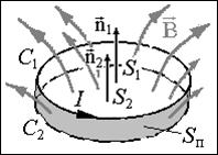 Figure 4.2.5 shows two sequential states of the circuit C 1 and C 2. The surfaces S 1 and S 2, which are limited by the contour in positions C 1 and C 2, and the surface S p, drawn by the contour, constitute a closed surface. According to the Ostrogradsky-Gauss theorem for magnetic induction, the total flux through this closed surface is zero. Let's choose normals n 1 and n 2 to surfaces S 1 and S 2 when calculating the flux linkages Y 1 and Y 2 in each position so that they are consistent with the direction of the current in the circuit according to the right-hand screw rule (from the end of the normal vector, the current in the circuit is seen going counterclockwise). In this case, the flow outward from the closed surface is the sum of the flow through S 1 in direction n 1 (equal to Y 1), flow through S 2 in the opposite direction n 2 (equal -
Y 2) and flow through the drawn surface S p (F m). Thus, we get
Figure 4.2.5 shows two sequential states of the circuit C 1 and C 2. The surfaces S 1 and S 2, which are limited by the contour in positions C 1 and C 2, and the surface S p, drawn by the contour, constitute a closed surface. According to the Ostrogradsky-Gauss theorem for magnetic induction, the total flux through this closed surface is zero. Let's choose normals n 1 and n 2 to surfaces S 1 and S 2 when calculating the flux linkages Y 1 and Y 2 in each position so that they are consistent with the direction of the current in the circuit according to the right-hand screw rule (from the end of the normal vector, the current in the circuit is seen going counterclockwise). In this case, the flow outward from the closed surface is the sum of the flow through S 1 in direction n 1 (equal to Y 1), flow through S 2 in the opposite direction n 2 (equal -
Y 2) and flow through the drawn surface S p (F m). Thus, we get
where ![]() . Therefore, relation (4.2.8) for a closed loop can be written as follows
. Therefore, relation (4.2.8) for a closed loop can be written as follows
When deriving this formula, we considered a simple movement of the contour, but it also turns out to be valid for more complex changes in the state of the contour, for example, during rotation and deformation. In this form, it is performed for the movement of not only a single circuit, but also a coil consisting of several turns, in particular, for a coil of N identical turns. In the latter case, the flux linkage is Y = N F m, where F m is the magnetic flux through one turn.
36) Magnetic dipole. Magnetic moment of a body and its magnetization.
In each atom, electrons move around the central nucleus, i.e. an elementary electric current arises.
Vector quantity, equal to the product of current i and elementary area S, limited by an elementary circuit with current, and directed perpendicular to this area according to Buravchik’s rule, is called magnetic moment elementary electric current.
The geometric sum of the magnetic moments of all elementary electric currents in a body gives the magnetic moment of the body M,
those. M=m 1 +m 2 +m 3 +…
the quantity measured by the ratio of the magnetic moment of a body to its volume (V) is called body magnetization Y.
37) Algorithm for calculating an unbranched magnetic circuit. Magnetomotive force (MF).
Electromagnets are widely used in electrical devices such as contactors, starters, relays, automatic machines, electromagnetic couplings, etc.
Let's consider the basic relationships for the magnetic circuit of an electromagnet using the example of a valve system (Fig. 4.4). The moving part of the magnetic circuit that creates the working force is called an armature 1 . Magnetic circuit sections 3 And 4 called rods or cores.
In a valve system, the armature can have both translational and rotational motion.
When current passes through the magnetizing coil 2 an MMF is created, under the influence of which a magnetic flux F is excited. This flux is closed both through the gap and between other parts of the magnetic circuit that have different magnetic potentials.
The air gap, which changes when the armature moves, is called working. Accordingly, the magnetic flux passing through the working gap is called working magnetic flux and is designated . All other fluxes in the magnetic circuit that do not pass through the working gap are called scattering fluxes .The electromagnetic force developed by the armature is determined by the magnetic flux in the working gap.
 When calculating the magnetic circuit, the MMF of the coil is determined, which is necessary to create a given working flow (direct problem), or the working flow is determined by the known MMF of the coil (inverse problem). These problems can be solved using laws
Kirchhoff for a magnetic circuit. According to Kirchhoff's first law, the algebraic sum of fluxes at any node of the magnetic circuit is zero
Kirchhoff's second law follows from the well-known law total current
![]() ,
,
Where N - magnetic field strength; - elementary section of the integration contour; - algebraic sum of the MMF acting in the circuit.
Because , then formula (4.2) can be written as follows:
![]() , or
, or ![]() , (4.3)
, (4.3)
Where - cross section of this section of the magnetic circuit; - absolute magnetic permeability of the area , equal ; Here - magnetic constant, - relative magnetic permeability.
Magnetic permeability characterizes the magnetic conductivity of the circuit material.
For air, the magnetic permeability is taken equal to the magnetic constant ![]() .
.
The expression is similar to the expression for the active resistance of the element electrical circuit(Where -
specific electrical conductivity of the conductor material). Then formula (4.3) can be represented as ![]() , (4.4)
, (4.4)
Where - magnetic resistance of a section of length .
A fall magnetic potential along a closed loop is equal to the sum of the MMF acting in this circuit. This is Kirchhoff's second law for a magnetic circuit.
When the flux in individual sections of the magnetic circuit does not change, the integral in (4.4) can be replaced by the finite sum
![]() . (4.5)
. (4.5)
Thus, sum of magnetic voltage drops over closed loop equal to the sum of the MMF acting in this circuit.
The direction of the MMF, coinciding with the direction of bypassing the contour, is taken as positive, opposite to it - for the negative. The direction of the bypass is usually taken to be the direction of the magnetic flux. From formula (4.5) Ohm’s law for a magnetic circuit follows, in this case, instead of current, magnetic flux is substituted, instead of electrical resistance - magnetic and instead of the EMF, the MMF is substituted.
By analogy with electrical resistance, the magnetic resistance of a section of finite length I can be represented as ![]() ,
,
Where - magnetic resistance per unit length of the magnetic circuit at cross section, also equal to one, m/Gn.
To calculate using formula (4.5), you need to know . If not a curve is specified , and the magnetization curve of the material , For calculation it is convenient to use formula (4.2). If the induction is constant in individual sections, then the integral in (4.2) can be replaced by the finite sum
![]() (4.6)
(4.6)
Using a known induction, the tension is found in each section using a curve , after which, using equality (4.6) we can
find the MDS coils.
When calculating a magnetic circuit, the reciprocal of magnetic resistance is often more convenient - magnetic conductivity, H.
![]() .
.
Equation (4.5)
it takes the form ![]() .
.
For the simplest unbranched circuit with conductivity
Magnetic resistance and conductivity of ferromagnetic materials are a complex nonlinear function of induction. The nonlinear dependence of magnetic resistance on induction greatly complicates the solution of both direct and inverse problems.
Magnetic conductivity of air gaps. In the working gap, the flow passes through air, the magnetic permeability of which does not depend on induction and is constant, equal to .
For rectangular and round poles with a small gap, the field can be considered approximately uniform, and the conductivity can be easily determined using the formula
Calculating conductivity taking into account buckling is associated with great difficulties due to the complexity of the magnetic field pattern. Three main methods are used for calculation:
1) Calculation using empirical formulas. So, for example, for the conductivity between the ends of cylindrical poles with a diameter, a fairly accurate result is given by the formula
 .
.
The last two terms take into account the bulging flow. For rectangular poles with transverse dimensions a and the formula is quite accurate
![]() .
.
2) When the analytical calculation of conductivity is difficult due to the complex field pattern, the real field is divided into simple geometric figures, for which there are calculation formulas conductivity determinations. The resulting conductivity is determined by the sum of the conductivities of individual figures.
3) If conductivity cannot be calculated by the first two methods, it is necessary to graphically construct a picture of the magnetic field. The field is divided into elementary tubes, within which the flux is the same, and the conductivity of the tube is determined. Total conductivity is determined by the total conductivity of all tubes.
38) The phenomenon of alternating current. Obtaining sinusoidal EMF
In one revolution the frame will rotate through an angle , and the revolution time is the period ( T), then the angular frequency is determined:
![]()