A parallel connection of resistances is a connection when the beginnings of the resistances are connected into one common point, and the ends go to the other.
The following properties are characteristic of parallel connection of resistances:
The voltages at the terminals of all resistances are the same:
U 1 = U 2 = U 3 = U ;
The conductivity of all parallel-connected resistances is equal to the sum of the conductivities of the individual resistances:
1/R = 1/R 1 + 1/R 2 + 1/R 3 = R 1 R 2 + R 1 R 3 + R 2 R 3 /R 1 R 2 R 3 ,
where R - equivalent (resultant) resistance three resistances(in this case R 1, R 2 and R 3).
To obtain the resistance of such a circuit, it is necessary to invert the fraction that determines the value of its conductivity. Therefore, the resistance of parallel branching of three resistors is:
R = R 1 R 2 R 3 / R 1 R 2 + R 2 R 3 + R 1 R 3 .
Equivalent resistance is a resistance that can replace several resistances (connected in parallel or in series) without changing the amount of current in the circuit.
To find the equivalent resistance in a parallel connection, it is necessary to add up the conductivities of all individual sections, i.e. find the total conductivity. The reciprocal of the total conductance is the total resistance.
With a parallel connection, the equivalent conductance is equal to the sum of the conductivities of the individual branches, therefore, the equivalent resistance in this case is always less than the smallest of the resistances connected in parallel.
In practice, there may be cases when a chain consists of more than three parallel branches. All obtained relationships remain valid for circuits consisting of any number of parallel-connected resistors.
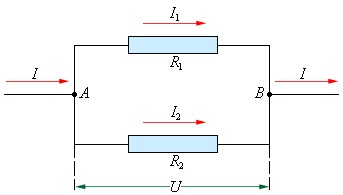
Let's find the equivalent resistance of two parallel-connected resistances R 1 and R 2 (see picture). The conductivity of the first branch is equal to 1/R 1 , conductivity of the second branch - 1/R 2 . Total conductivity:
1/R = 1/R 1 + 1/R 2 .
Let's lead to common denominator:
1/R = R 2 + R 1 /R 1 R 2 ,
hence the equivalent resistance
R = R 1 R 2 / R 1 + R 2.
This formula is used to calculate the total resistance of a circuit consisting of two resistances connected in parallel.
Thus, the equivalent resistance of two parallel-connected resistances is equal to the product of these resistances divided by their sum.
In parallel connection n equal resistance R 1 their equivalent resistance will be in n times less, i.e.
R = R 1 /n.
In the diagram shown in the last figure, five resistances are included R 1 30 ohms each. Therefore, the total resistance R will be
R = R 1 /5 = 30/5 = 6 ohms.
We can say that the sum of the currents approaching the nodal point A (in the first figure) is equal to the sum of the currents leaving it:
I = I 1 + I 2 + I 3.
Let's consider how current branching occurs in circuits with resistances R 1 and R 2 (second picture). Since the voltage at the terminals of these resistances is the same, then
U = I 1 R 1 and U = I 2 R 2.
The left sides of these equalities are the same, therefore the right sides are also equal:
I 1 R 1 = I 2 R 2,
or
I 1 /I 2 = R 2 /R 1,
Those. When resistances are connected in parallel, the current branches out in inverse proportion to the resistances of the branches (or directly proportional to their conductivities). The greater the resistance of a branch, the less current in it, and vice versa.
Thus, from several identical resistors you can get a common resistor with greater power dissipation.
When unequal resistors are connected in parallel, the highest power resistor releases the most power.
Example 1. There are two resistances connected in parallel. Resistance R 1 = 25 Ohm, and R 2 = 50 Ohm. Determine the total resistance of the circuit Rtot.
Solution. R total = R 1 R 2 / R 1 + R 2 = 25. 50 / 25 + 50 ≈ 16.6 ohms.
Example 2. A tube amplifier has three tubes, the filaments of which are connected in parallel. First lamp filament current I 1 = 1 ampere, second I 2 = 1.5 amps and third I 3 = 2.5 amps. Determine the total filament current of the amplifier lamps I general
Solution. I total = I 1 + I 2 + I 3 = 1 + 1.5 + 2.5 = 5 amperes.
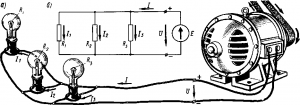
Parallel connection of resistors is often found in radio equipment. Two or more resistors are connected in parallel when the current in the circuit is too high and would cause the resistor to heat up excessively.
An example of parallel connection of consumers electrical energy can serve as turning on electric lamps as usual lighting network which are connected in parallel. The advantage of parallel connection of consumers is that turning off one of them does not affect the operation of others.
Series, parallel and mixed connections of resistors. A significant number of receivers included in the electrical circuit (electric lamps, electric heating devices, etc.) can be considered as some elements that have a certain resistance. This circumstance gives us the opportunity, when drawing up and studying electrical circuits, to replace specific receivers with resistors with certain resistances. There are the following methods resistor connections(receivers of electrical energy): serial, parallel and mixed.
Series connection of resistors.
For serial connection several resistors, the end of the first resistor is connected to the beginning of the second, the end of the second to the beginning of the third, etc. With this connection, all elements series circuit passes
the same current I.
The serial connection of receivers is illustrated in Fig. 25, a.
.Replacing the lamps with resistors with resistances R1, R2 and R3, we get the circuit shown in Fig. 25, b.
If we assume that Ro = 0 in the source, then for three series-connected resistors, according to Kirchhoff’s second law, we can write:
E = IR 1 + IR 2 + IR 3 = I(R 1 + R 2 + R 3) = IR eq (19)
Where R eq =R 1 + R 2 + R 3.
Consequently, the equivalent resistance of a series circuit is equal to the sum of the resistances of all series-connected resistors. Since the voltages in individual sections of the circuit are according to Ohm’s law: U 1 =IR 1 ; U 2 = IR 2, U 3 = IR 3 and in this case E = U, then for the circuit under consideration
U = U 1 + U 2 + U 3 (20)
Consequently, the voltage U at the source terminals is equal to the sum of the voltages at each of the series-connected resistors.
From these formulas it also follows that the voltages are distributed between series-connected resistors in proportion to their resistances:
U 1: U 2: U 3 = R 1: R 2: R 3 (21)
that is, the greater the resistance of any receiver in a series circuit, the greater the voltage applied to it.
If several, for example n, resistors with the same resistance R1 are connected in series, the equivalent circuit resistance Rek will be n times more resistance R1, i.e. Rec = nR1. The voltage U1 on each resistor in this case is n times less than the total voltage U:
When receivers are connected in series, a change in the resistance of one of them immediately entails a change in the voltage at the other receivers connected to it. When turned off or interrupted electrical circuit the current stops in one of the receivers and in the other receivers. Therefore, series connection of receivers is rarely used - only in the case when the voltage of the electrical energy source is greater than the rated voltage for which the consumer is designed. For example, the voltage in electrical network, from which subway cars are powered, is 825 V, while the nominal voltage of the electric lamps used in these cars is 55 V. Therefore, in subway cars, electric lamps are switched on in series, 15 lamps in each circuit.
Parallel connection of resistors. In parallel connection several receivers, they are connected between two points of the electrical circuit, forming parallel branches (Fig. 26, a). Replacing
lamps with resistors with resistances R1, R2, R3, we get the circuit shown in Fig. 26, b.
When connected in parallel, the same voltage U is applied to all resistors. Therefore, according to Ohm’s law:
I 1 =U/R 1; I 2 =U/R 2; I 3 =U/R 3.
Current in the unbranched part of the circuit according to Kirchhoff’s first law I = I 1 +I 2 +I 3, or
I = U / R 1 + U / R 2 + U / R 3 = U (1/R 1 + 1/R 2 + 1/R 3) = U / R eq (23)
Therefore, the equivalent resistance of the circuit under consideration when three resistors are connected in parallel is determined by the formula
1/R eq = 1/R 1 + 1/R 2 + 1/R 3 (24)
By introducing into formula (24) instead of the values 1/R eq, 1/R 1, 1/R 2 and 1/R 3 the corresponding conductivities G eq, G 1, G 2 and G 3, we obtain: equivalent conductivity parallel circuit equal to the sum of the conductances of parallel connected resistors:
G eq = G 1 + G 2 + G 3 (25)
Thus, as the number of resistors connected in parallel increases, the resulting conductivity of the electrical circuit increases, and the resulting resistance decreases.
From the above formulas it follows that currents are distributed between parallel branches in inverse proportion to their electrical resistance or directly proportional to their conductivity. For example, with three branches
I 1: I 2: I 3 = 1/R 1: 1/R 2: 1/R 3 = G 1 + G 2 + G 3 (26)
In this regard, there is a complete analogy between the distribution of currents along individual branches and the distribution of water flows through pipes.
The given formulas make it possible to determine the equivalent circuit resistance for various specific cases. For example, with two resistors connected in parallel, the resulting circuit resistance is
R eq =R 1 R 2 /(R 1 +R 2)
with three resistors connected in parallel
R eq =R 1 R 2 R 3 /(R 1 R 2 +R 2 R 3 +R 1 R 3)
When several, for example n, resistors with the same resistance R1 are connected in parallel, the resulting circuit resistance Rec will be n times less than the resistance R1, i.e.
R eq = R1/n(27)
The current I1 passing through each branch, in this case, will be n times less than the total current:
I1 = I/n (28)
When the receivers are connected in parallel, they are all under the same voltage, and the operating mode of each of them does not depend on the others. This means that the current passing through any of the receivers will not have a significant effect on the other receivers. Whenever any receiver is turned off or fails, the remaining receivers remain on.
valuable. Therefore, a parallel connection has significant benefits before the sequential one, as a result of which it became most widespread. In particular, electric lamps and motors designed to operate at a certain (rated) voltage are always connected in parallel.
On electric locomotives DC and on some diesel locomotives, traction motors need to be switched on at different voltages during speed control, so they switch from a series connection to a parallel connection during acceleration.
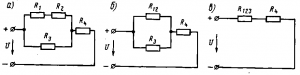
Mixed connection of resistors. Mixed compound This is a connection in which some of the resistors are connected in series, and some in parallel. For example, in the diagram of Fig. 27, and there are two series-connected resistors with resistances R1 and R2, a resistor with resistance R3 is connected in parallel with them, and a resistor with resistance R4 is connected in series with a group of resistors with resistances R1, R2 and R3.
The equivalent resistance of a circuit in a mixed connection is usually determined by the conversion method, in which a complex circuit is converted into a simple one in successive steps. For example, for the diagram in Fig. 27, and first determine the equivalent resistance R12 of series-connected resistors with resistances R1 and R2: R12 = R1 + R2. In this case, the diagram in Fig. 27, but is replaced by the equivalent circuit in Fig. 27, b. Then the equivalent resistance R123 of parallel-connected resistances and R3 are determined using the formula
R 123 = R 12 R 3 / (R 12 + R 3) = (R 1 + R 2) R 3 / (R 1 + R 2 + R 3).
In this case, the diagram in Fig. 27, b is replaced by the equivalent circuit of Fig. 27, v. After this, the equivalent resistance of the entire circuit is found by summing the resistance R123 and the resistance R4 connected in series with it:
R eq = R 123 + R 4 = (R 1 + R 2) R 3 / (R 1 + R 2 + R 3) + R 4
Series, parallel and mixed connections are widely used to change the resistance of starting rheostats when starting an electric power plant. p.s. DC.
1. For serial connection conductors
1. The current strength in all conductors is the same:
I 1 = I 2 = I
2. Total voltage U on both conductors is equal to the sum of the voltages U 1 and U 2 on each conductor:
U = U 1 + U 2
3. According to Ohm's law, voltage U 1 and U 2 on the conductors are equal U 1 = IR 1 , U 2 = IR 2 a total voltage U = IR Where R – electrical resistance the whole chain, then IR= IR 1 + IR 2. It follows
R= R 1 + R 2
For serial connection impedance circuit is equal to the sum of the resistances of the individual conductors.
This result is valid for any number of conductors connected in series.
2. In parallel connection conductors
1. Voltages U 1 and U 2 are the same on both conductors
U 1 = U 2 = U
2. Sum of currents I 1 + I 2 , flowing through both conductors is equal to the current in an unbranched circuit:
I = I 1 + I 2
This result follows from the fact that at current branching points (nodes A And B) charges cannot accumulate in a DC circuit. For example, to the node A in time Δ t charge is leaking IΔ t, and the charge flows away from the node at the same time I 1Δ t + I 2Δ t. Hence, I = I 1 + I 2 .
3. Writing based on Ohm's law
Where R– electrical resistance of the entire circuit, we get
When connecting conductors in parallel, the value is the inverse general resistance circuit is equal to the sum of the reciprocal values of the resistances of parallel-connected conductors.
This result is valid for any number of conductors connected in parallel.
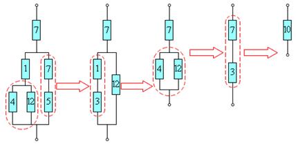
Formulas for series and parallel connection of conductors allow in many cases to calculate the resistance of a complex circuit consisting of many resistors. The figure shows an example of such a complex circuit and indicates the sequence of calculations. The resistances of all conductors are indicated in ohms (Ohms).
In practice, one current source in a circuit is not enough, and then the current sources are also connected to each other to power the circuit. The connection of sources to a battery can be serial or parallel.
In a series connection, two adjacent sources are connected by opposite poles.
That is, for series connection of batteries, to the “plus” electrical diagram connect the positive terminal of the first battery. The positive terminal of the second battery is connected to its negative terminal, etc. The negative terminal of the last battery is connected to the “minus” of the electrical circuit.
The resulting battery in series connection has the same capacity as a single battery, and the voltage of such a battery is equal to the sum of the voltages of the batteries included in it. Those. If the batteries have the same voltage, then the battery voltage is equal to the voltage of one battery multiplied by the number of batteries in the battery.
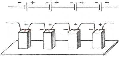
1. The emf of the battery is equal to the sum of the emf of individual sourcesε= ε 1 + ε 2 + ε 3
2 . The total resistance of the source battery is equal to the sum of the internal resistances of the individual sources r batteries = r 1 + r 2 + r 3
If n identical sources are connected to a battery, then the emf of the battery is ε = nε 1, and the resistance r of the battery = nr 1
3.
In a parallel connection, all positive and all negative poles of two orn sources.
That is, with a parallel connection, the batteries are connected so that the positive terminals of all batteries are connected to one point of the electrical circuit ("plus"), and the negative terminals of all batteries are connected to another point of the circuit ("minus").
Connect in parallel only sources With the same EMF. The resulting battery in parallel connection has the same voltage as a single battery, and the capacity of such a battery is equal to the sum of the capacities of the batteries included in it. Those. if the batteries have the same capacities, then the capacity of the battery is equal to the capacity of one battery multiplied by the number of batteries in the battery.
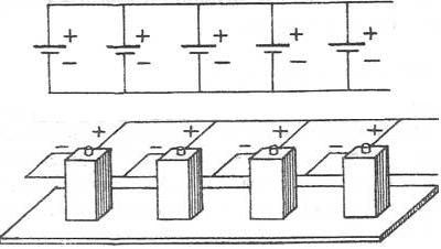
1. The emf of a battery of identical sources is equal to the emf of one source.ε= ε 1 = ε 2 = ε 3
2.
Battery resistance is less than single source resistance r batteries = r 1 /n
3.
Current strength in such a circuit according to Ohm's law
The electrical energy accumulated in a battery is equal to the sum of the energies of individual batteries (the product of the energies of individual batteries, if the batteries are the same), regardless of whether the batteries are connected in parallel or in series.
The internal resistance of batteries manufactured using the same technology is approximately inversely proportional to the battery capacity. Therefore, since with a parallel connection the capacity of the battery is equal to the sum of the capacities of the batteries included in it, i.e. it increases, then internal resistance decreases.