Hello, dear reader of my blog. Today I will tell you how to assemble a 220V electricity metering panel. The question is quite complex and if you are not confident in your abilities, then it is better not to take on such a responsible job, since mistakes here are fraught with dire consequences in the form of a short circuit and fire. At the end of this article I will show a diagram where everything will become clear to you. Any malfunctions in the metering panel can cause the failure of expensive electrical equipment, from heating boilers to .
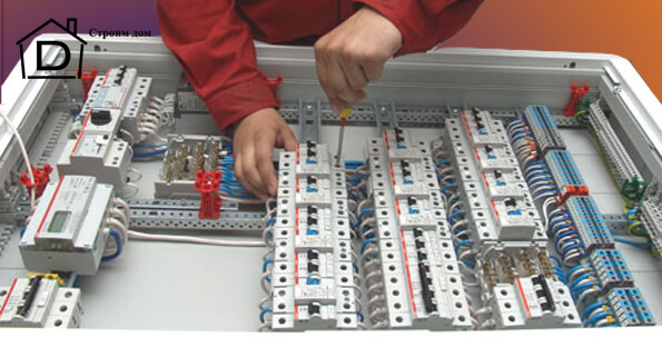
And so let’s get started, as the name suggests (metering board), this board is used to account for the electricity you consume. Therefore, it must have a counter.
Selecting the number of circuit breakers
But first of all, you need the box itself (shield) in which you will install everything. It is selected based on quantity circuit breakers(“Automatic machines”), but how many of them to install is up to you. You can at least install a separate circuit breaker for each socket and switch. But of course this will be unnecessary. It is best to separate outlets and lighting. That is, one machine for lighting and another for sockets. If the consumption is too high, then you can, for example, connect 2 rooms to one pair of machines, and the remaining rooms are for another pair. By the word pair, I mean two machines, one for “light” and the other for sockets. If any device in the house consumes more than 5 kilowatts, then it must be connected to a separate line(and accordingly a separate machine). These are devices such as an electric stove, electric boiler, etc. It is also recommended to connect the washing machine to a separate line. And, of course, you need to keep a couple of spare machines in case a new consumer appears in the house. At the input, it is also advisable to install a two-pole circuit breaker (double) as well as an RCD and OPS, but more on that later.
Selecting the power of circuit breakers

In the previous article, I already told you about the choice of wire cross-section and that a cross-section of 2.5mm² goes to sockets, and 1.5mm² to lighting. So here it is machines are selected based on the wiring cross-section, so that it can turn off before your wire starts to melt from overload. It turns out that a machine with a power rating of 25A (ampere) is installed on a 2.5mm² wire, and with a power rating of 16A on a 1.5mm² wire. Below is a table showing which section it is recommended to install which machine and what is the maximum load of such a wire:
| Section of copper conductors of wires, sq. mm | Permissible continuous load current for wires, A | Rated current circuit breaker, A | Maximum current of the circuit breaker, A | Maximum power of single-phase (220V) load KW | Characteristics of household load (220V) |
| 1.5 | 19 | 10 | 16 | 4,1 | Lighting and alarm |
| 2.5 | 27 | 16 | 20 | 5,9 | Socket groups and electric floors |
| 4 | 38 | 25 | 32 | 8,3 | Water heaters and air conditioners |
| 6 | 46 | 32 | 40 | 10,1 | Electric stoves and ovens |
| 10 | 70 | 50 | 63 | 15,4 | Opening lines |
What is an RCD and why is it needed?

We will assume that you have decided on the number and power of machines. Next, let's talk about the RCD. RCD is a device protective shutdown, designed to protect against current leakage. In our case, current leakage refers to electricity that passes by electrical wiring and electrical appliances. The task of this device is to detect this leak and turn off the power. In simple words if you grab 2 bare wires, the device will turn off the current before you feel the electric shock, but this is in theory))). This device also has overload protection (like a machine). RCDs come in the same ratings as automatic machines (10A, 16A, 25A, etc.). In general, RCD is very useful thing, which triggers at the slightest current leakage, so do not neglect such protection. Let's say for an electric motor washing machine, wire insulation is frayed (Phase) in this case, the body of your machine will be energized(and you don’t know this). Without an RCD, unpleasant consequences will await you. You can give a bunch of other situations in which this device would be useful, but I think this is unnecessary. I believe you have already chosen for yourself whether you will install it or not.
OPS what is it and what is it for?
And so we will continue to disassemble the assembly of the 220V electricity metering panel. The next element we will look at is an element called Surge Suppressor (Surge Suppressor). This device is designed to protect against incoming overvoltages (for example, lightning). But for correct operation it requires grounding. It is installed in the switchboard parallel to the input machine(the diagram will show it in detail later). Operating principle of this device lies in the fact that when overvoltage occurs, the OPS creates within itself short circuit, as a result of which the input circuit breaker is turned off, thereby blocking the further path of overvoltage into your home network, and the current that has passed is discharged to grounding. It is believed that this device is disposable and after overvoltage it fails. It looks like an ordinary single-pole circuit breaker, only in place of the “flag” of the switch there is an operating status indicator on it (when it is green, it means the device is working; if red, then it is out of order). If you connect to the mains new home, then installation of OPS is required. If you are simply repairing the wiring, then this issue remains at your discretion. OPS are divided into three categories: “B”, “C”, “D”.
Class "B"
Mounted at the entrance to the room in the main switchboard (main switchboard.) Is protection against lightning strikes and overvoltage.
Class "C"
Mounted indoors in the distribution board (distribution board). Designed to protect internal wiring and circuit breakers. They protect against residual overvoltages that have passed through class “B”. The most common option, which is installed most often.
Class "D"
Installed directly on the consumer. Protects the consumer from high-frequency interference and overvoltages that have passed through class “C”.
Counter selection
To assemble a 220V electricity metering board, you cannot do without a meter. Meters are electromechanical and electronic. Electromechanical meters have a mechanical reference mechanism, of course, they differ from their predecessors with a disk. Now the disk has been replaced LED indicator. When disconnected of this device from the network, all readings remain on the display.
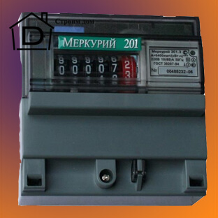
It has a liquid crystal display on which readings are displayed. The error, like that of a mechanical analogue, is within 1%. This counter differs from a mechanical one in that if the device is disconnected from the network or breaks down, you will not be able to see the readings. Although electronic meters have more advanced functionality. Besides energy consumed it can show the amount of active and reactive energy and much more (depending on the model). Many models are also equipped with a function for remote transmission of readings.
Meters are also divided into single-tariff and double-tariff. Single tariff meters They calculate electricity at one tariff, that is, at a daily rate, and you pay a certain amount for each kilowatt. In most cases, such meters are equipped mechanical system accounts, but there are exceptions (that is, it may be electronic).
Two-tariff meter calculates electricity at 2 tariffs. Day and night. The day rate is considered the same as for a single tariff, but the daily rate runs from 8:00 to 23:00. The night rate starts from 23:00 to 8:00, but you will pay almost half as much for it. But such a device costs twice as much.

Accuracy class - This is an indicator of the error of the electric meter. Now new models come with accuracy class 2 and higher, which is allowed in any electrical network. So you shouldn’t focus on this parameter.
Counter sizes
The size of the counters can also be different. There are big and small ones. Quality has nothing to do with size. Large counters require a separate space in the drawer (there are special places in the drawer reserved for this). Small ones are installed in the same way as automatic machines and do not require a specially designated space for themselves.
Shield selection
Once you have decided on all of the above (automatic machines, RCD, OPS, counter), it’s time to choose a box for all this. Namely, based on the number of machines, the size of the counter, etc. Shields come in plastic and metal versions, hidden and open mounting. Here again, it all depends on the conditions in which you will carry out the installation. There are markings on the boxes indicating how many circuit breakers they are designed for, so everything is selected individually. But you should not choose a box that is too small, as it will be inconvenient to install.

Well, the last thing I can advise is to take into account the degree of “dust and moisture protection”. It is marked, for example: IP65. Below is a table of the degree of protection.
Table of degree of moisture protection. 
Well, we have gradually come to the most important answer to the question: How can we assemble a 220 V electricity metering panel? Below is an assembly diagram, but now I will try to explain everything to you in words. And so the first thing we will start with is installing an introductory machine (hereinafter referred to as VA). I will give an example with the installation of RCD and OPS; if you do not install them, then you simply skip this moment. Next, an OPS is installed parallel to the input machine (that is, phase wire from the VA it goes to the fire alarm system, and from there to the grounding bus). Next, the “phase” and “zero” wires from the VA go to the meter, and from the meter to the RCD. And from the RCD, all groups of machines are connected with the “phase” wire, and the zero wire goes to the zero bus (usually the buses are included in the kit, but if they are not available, you will have to buy them in addition). Groups of machines can be connected by a special bus or by jumpers made of 6mm² wire.
All that remains is to connect the VA with the “supply” wire. You can mount it in any color you like, but it’s better to follow the standard. Blue or brown is “zero”, white or red is “phase”, yellow-green is grounding. And here is the assembly diagram itself:


Well, that’s basically all I wanted to say. When tightening contacts on automatic machines, tighten them with maximum force (if you do not tighten them enough, over time the contact will “loose” and begin to heat up, with all the ensuing consequences). Thank you for your attention. Good luck with your renovation!
I'm tired of seeing crooked three-phase shields that are never optimal, clumsy and terrible in terms of people's use, repair, and load redistribution among phases. In this area, something also needs to be changed and made more pleasant and convenient both for those people who develop these shields and for those people who will use these shields. Therefore, I continue my master class in order to teach people how to make simple, but hellishly evil and flexible three-phase shields.
And before we get to the theory, let's remember the previous posts that I had on this topic. Firstly, initially there was this post about three-phase shields: ““. There I showed how I assemble a three-phase shield on the DS201/202C series difavtomats, thanks to which it is flexible and easy to maintain. Secondly, you should read the post about, in which I talked about the entire general theory of design and assembly of shields: markings, documentation, connections. This post will be useful to us to refresh our knowledge on the installation itself, which I will omit here.
Update from March 2017. In general, this three-phase budget scheme is only good in terms of the cost of materials. But assembling this shield and servicing it is much more difficult than the shield on difs: after all, in the shield on difs we have only one cross-module, but in budget three-phase shields there are more cross-modules, and more free space must be left around them. And this will make our shield even larger. You will still have to pay for something: either for the cost of the shield (on diffs) or for its size (according to the budget scheme). I myself am returning to three-phase switchboards on type “A” automatic circuit breakers, and I will only do a three-phase budget circuit if the situation is completely hopeless, huh.
Announcement from April 2017. This shield scheme has outlived its usefulness. It really helped to survive the shock of the crisis of 2015-2016, but now it’s time to get used to the new prices, and after I got a 15-line bathhouse shield with FIVE cross-modules and barely fit into AT52 (or better yet AT62 ), I'm switching back to automatic machines. I use the DS201 series 6 kA and type "A". Such automatic machines cost 5-6 thousand apiece, but it pays off in the following ways:
- The shield size becomes smaller. Well, or you can put it in the same size more features(automation, non-disconnected lines, etc.).
- There are fewer wires inside the shield, because the hellish harnesses from the RCD to the cross-modules disappear and because there are fewer cross-modules.
- The shield turns out to be more logical: cross-modules will only be needed for the right types power supply (non-switchable, network, generator, and so on), and not for each RCD, and no one will get confused in them.
- For the user, it turns out that each line has its own full-fledged protection: an RCD and a machine in one housing. And if there are problems with one line, it will not affect the others. This is especially true if the leak on the line is floating: sometimes it appears, sometimes it doesn’t. In the case of RCDs and automatic machines, you can spend a lot of time looking for this, but in the case of differentials, one of them will simply turn off, even if no one is at home, and the rest will work.
As for money, I don’t consider myself guilty for the high cost of materials. The crisis has passed, prices have risen and I am forced to work according to them, because I am not the one who comes up with the prices for materials. That's all. From now on, by default, I count all three-phase shields on differentials, and only if the situation is COMPLETELY hopeless, then according to the budget scheme. But if you agreed to it, then be prepared for the fact that instead of a shield you will have a 2x1 meter cabinet.
Part 1. Theory of development of a three-phase shield.
What is the most basic thing in the world for us after we have chosen the lines correctly, their protection and where they go and what they feed? For us, the most important thing is to make the shield clear and convenient for the person. And the location of the machines and their signatures depends on this. That is, we need to have light machines first, then outlet machines, then kitchen machines, then bathroom machines, then all sorts of climate control equipment, for example.
Do you remember how we assemble a single-phase panel (from the previous master class)? Everything is simple there: there we sort the circuit breakers as needed (because all the lines are on the same phase and in this regard they are all equal), and then we arrange the differential protection () so that the operation of one RCD does not particularly affect the other lines. Let's say, if the entire kitchen shuts down, then we can drag the microwave and kettle to another room and heat up the food. Or if the air conditioners and warm floors are cut off, then we won’t care.
But in case of three phases, we have two tasks at once, which are completely opposite to each other in logic. This is the same task of distributing all lines according to differential protection and at the same time according to different phases. And this is where the difficulties begin, because the distribution by phase will give us one logical sorting of lines (for example, Kitchen Sockets and Boiler Power, Street Light), and the distribution for a person, which is most important, should give the sorting of lines that I described above.
And we need to install differential protection! Moreover, in such a way that if it is available, it would be possible to change the phase distribution using cross-modules. Just in case, I remind you that a cross-module is a contraption that contains two or four buses that can be used to supply phases (phase) and zero to them once, and then distribute them from this point to other places of the shield. And if we need to change the distribution of loads across phases, then it is enough to unscrew the wire of this load from one phase bus and screw it into another bus.
So, the most competent and the right decision for a three-phase shield, it is to assemble it using difautomats. For example, . In this case, we do everything as I described in, to which I already gave a link.
We put the automatic machines in a row and take advantage of the fact that the DS201/202C series has the same contacts as the S200 series machines. In this case we can even combine the usual two-pole circuit breakers series S200 (S202) where differential protection is not needed and differential automatics. We connect all their zeros using a comb.
I use the comb 2CDL210001R1057 PS1/57N, which has blue. I asked ABB to keep it in small quantities in a warehouse in Moscow, and it is often in stock and available for order there. I bite out one tooth at a time and it becomes suitable for commuting zeros.
Well, in this case we connect each phase with its own wire from the cross-module. We will get this picture:

I have always collected such shields and have never made them differently. But now the crisis has struck (and prices have doubled), and three-phase power supply is becoming more and more widespread.
What to do to assemble a three-phase panel on a budget? Collect it on RCDs and automatic machines! But how? How? After all, here the task immediately arises of grouping lines by phase and by RCD at the same time, which is normally compatible. Why is it not compatible? But now I’ll show you.
Option 1. Replace difavtomats with the pair “UZO+Avtomat”. It can be used, but assembling the shield will be inconvenient, because there will be no clarity, which is obtained with differentials or with the option where the RCD and automatic devices are separate.
Option 2. Install a two-pole RCD for each phase. Then for the entire huge three-phase panel we will get only three RCDs and a bunch of automatic devices. The shield diagram will look like this:
And here the darkness of the design’s disadvantages immediately arises:
- Zero tires appear. This is VERY bad in three-phase switchboards. But not because the zero supposedly falls off inside the shield. And because there is extra fuss with these zeros after the RCD: you have to remember where to connect which, think about how to place these busbars. And one more thing that will be in the last point of shortcomings;) *here is an evil laugh*.
- Location of machines: or we put them in discord that is bad for the user, but we connect them with a comb and get beautiful installation shield, or we install them well for the user (and this is the most important thing!), but we get a bad installation of the shield, because we will have to connect all the machines of the required phase with a cable using NShVI (2) tips.
- Complete impossibility of switching a specific machine to another phase. In order to switch any machine from the circuit, for example “Dishwasher”, from phase “L1” to phase “L3”, we will have to throw it out of the comb or cut its cable. And then reach it with a wire from another RCD. And that's half the trouble. Because in addition to the phase, we also need to switch the zero to another RCD! This means that the zeros must be signed somehow, leaving a place in the shield for their marking.
In short, in order to switch the machine to another phase, you will have to tear out and redo the installation of the shield. That is, the customer must be given a WS-04A crimp, NShVI and NShVI(2) terminals and a PuGV mounting wire in the kit.
If we really want to get absolutely budget shield for three phases (if, for example, we have only a dozen lines), then it is better to install one four-pole RCD, a cross-module, and distribute the machines through it. Then the zero bus will be common, and it will be possible to switch loads by phase. I once assembled a shield like this. Here's what it looks like (from an old post):

That is, this option turns into the option “ One four-pole RCD and a bunch of automatic machines"and is suitable for some kind of panel of a barn, garage or utility room. And we are presented with a third option:
Option 3. To make it more convenient to switch lines by phase, we will divide the general RCDs into several separate two-pole ones. That is, the logic could be like this: let’s see which lines hang at which phase. And then we will try to come up with an RCD for them in such a way that this RCD receives one phase that these lines need, and at the same time these lines make at least some logical sense together. After this we will get the following diagram:
Do you want to know what her shortcomings are? Yes, ALL the same ones that were in the previous one! Even MORE fucking zero tires appear, but there is even less meaning left! And the same problem with switching lines by phase becomes more fun: we can either switch one RCD with its circuit breakers entirely, or we will again have to cut the wires in the panel and reassemble it.
See how terrible such a shield can look (from the post ““):
Do you see HOW MANY zero tires there are?! If you enlarge the picture, you can see the cables on the machines, which are almost impossible to redo! That is, this is a dead shield: it will not be flexible and the only thing that can be done with it is to add new lines from the cross-module.
We need to think again! Let's remember what requirements we place on a three-phase panel:
- People-oriented. Living people will use the shield. And they should not be glitched by the arrangement of lines like “Kitchen sockets”, “Street light”, “Attic sockets”, “Boiler”, “Bathroom light”. Because in such an arrangement of lines you will not understand where to look for the next one: at the beginning of the list, at the end, or even “somewhere”.
- Flexibility. Ability to switch any line to any phase if required. Possibility to add new lines (machines) to the panel.
- Defensive protection to all lines where it is needed. Because people need to be protected!
If we leave the logical grouping of lines and remember that there are four-pole RCDs, then we get an interesting option.
Option 4. Four-pole RCDs and Two-pole circuit breakers.
What are we doing? We take the best from all previously described options: two-pole connections to get rid of zero busbars; RCDs for differential protection, because they are cheaper than automatic devices; cross-modules for switching loads across different phases. And we get this shield diagram:

Here we took bipolar machines in order to connect all the zeros again with a PS1/57N comb and not think about them at all. We can arrange these machines the way we want, without thinking about which phase it will be in. Because we installed cross-modules before the machines. But before the cross-modules we installed differential protection in the form four-pole RCD.
There will not be many RCDs per panel, but they will protect many machine guns at once. Let's say, if we need to heavily budget for the panel board of a cottage, then we can make an RCD for the first floor, an RCD for the second floor, an RCD for the equipment and an RCD for the kitchen and bathrooms. We choose the current rating of the RCD no less than the input circuit breaker or with a reserve for the future. If I know for sure that the input circuit breaker will not rise above 25A (this corresponds to 15 kW per three phases), then I set the RCD to 25A. And if there is a reserve, then I set the RCD to 40A.
And then an experienced person will ask the question: how is this so? We usually try to increase the number of RCDs in such a way that if one RCD works in such a way that you can’t turn it back on without tinkering with the lines, we still have at least something working. And then it turns out that the entire first floor is cut off - and hello?
But this is where two-pole circuit breakers really help us! Thanks to them, we can not only use cross-modules and get rid of zero buses, but also quickly restore the functionality of the lines. Let's remember together what options for triggering an RCD we may have? The RCD can trip if there is a leak from a phase to PE, or if there is a leak from zero to PE. Now, if in the first case we only need to remove a phase from the line (by turning off the single-pole circuit breaker), then in the second case we must have either many RCDs (as in a single-phase panel - there we give preference to the operability of the lines), or install two-pole circuit breakers that turn off just phase and line zero at the same time.
That is, if one of the “large” RCDs triggered, the algorithm for finding the problem will be like this:
- We turn off all the machines that are under this RCD.
- We cock the RCD. Here it will immediately be clear what is buggy. When all the machines are turned off, the RCD should turn back on (if there are no deep problems in the panel). And if the RCD does not turn on, then there is a possibility that it has died on its own.
- We begin to turn on the line machines that are located under this RCD. As soon as we get to the problem line, our RCD will turn off again.
- We turn off the machine of the problem line (on which the RCD was knocked out), and continue to turn on the machines further.
As a result, all the problem lines will be turned off, and the rest will work. And this justifies the fact that we have so reduced all the RCDs in our panel. If you show or teach a little, even a schoolboy can handle this method of finding problems, and that’s good.
Well, we can switch lines by phase in the same way as usual: by rearranging the wires along the cross-module buses. The only difficulty when we need to shake up the entire panel is if we want a specific machine to stand under a completely different RCD.
Let's just for fun estimate the budget of such a shield based on prices from ETM. Let's say we have 20 lines. Divide them into two RCDs.
- 20 automatic machines S202 C16 (2CDS252001R0164): 775 rubles x 20 = 15,500 rubles
- 2 pieces of RCD F204 AC-40/0.03 (2CSF204001R1400) 3891 x 2 = 7,782 rub.
- 2 pieces of cross-modules IEK YND10-4-07-100 664 x 2 = 1,328 rub.
The amount turns out to be RUB 24,610. Now let’s take 20 pieces of DS201 C16 AC30 (2CSR255040R1164) differentials: 3946 * 20 = 78 920 . The difference in cost is three times! That is, if we need to save money during a crisis, this option is absolutely suitable and has the right to life.
What disadvantages might this option have?
- It eats up about twice as much space in the shield as the shield on automatic rifles. In some cases this may be important. For example, when you need to strictly meet right size shield, or when a shield twice as large in cost kills the entire monetary difference of this option.
- Well, and the fact that you will have to run to the panel more often in case of leaks: there are fewer RCDs, and they protect many lines each at once.
But switching lines by phase and adding new ones, ease of connection to the panel and its clarity remain the same as in the panel on automatic machines. And now I often began to use this option when I come up with shields for someone. For example, I have just such a shield.
Part 2. We assemble a three-phase shield according to the diagram.
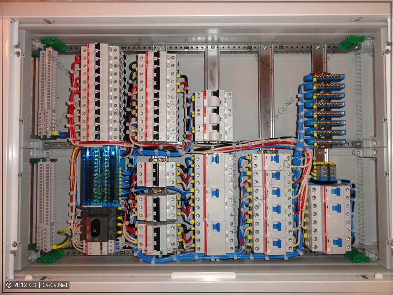
Now I will tell you about this shield in more detail. One customer asked me to quickly assemble a three-phase panel instead of a single-phase one, because everyone in their area was being switched to three-phase power. I sat and looked at the old lines that had already been laid and came up with a shield for him according to this scheme.
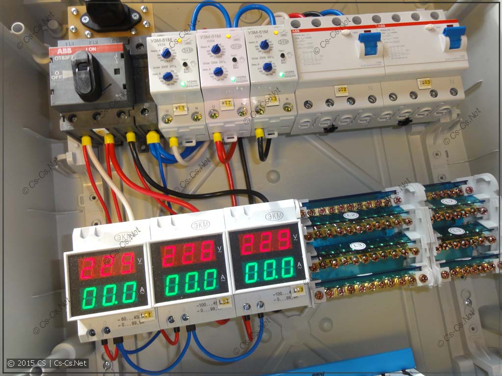
There will be no diagram of the panel, because it is terribly standard and is drawn above for any such panel: there is a switch at the input to make it convenient to connect the input cable and quickly turn off the entire panel. After this, the power passes through Meander VAR-M01 voltmeter-ammeters, then goes through three UZM51-m units to protect against burnout of the main zero or the input voltage curve. Then this power is supplied to two RCDs, and from them through cross-modules to the machines.
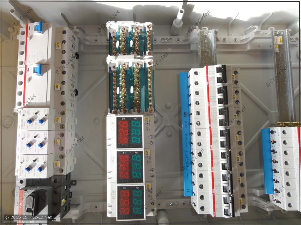
And it turned out so funny that Mistral IP65 was again chosen as the panel body, as in the panel for the single-phase master class. We arrange all the components in a panel (here it has 72 modules, and the width of the DIN rail is 18 modules):

Next we cut off and place the combs on the RCDs and automatic machines. Just in time for us and for such a shield design, the ABB PS4/12 comb is available (part number 2CDL240101R1012). This comb allows you to connect together three pieces of four-pole RCDs, because its diagram is like this: L1-L2-L3-N-L1-L2... This comb looks like this:

I sawed it off to the width of two narrow boxes and screwed it to them:
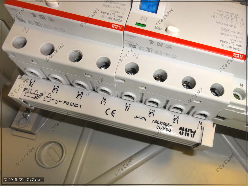
And its convenience is that if you forget about the Mistral, then it exactly fits three RCDs standing on one DIN rail for 12 modules, which is the standard for ABB switchboards.
We connect the zeros again with a PS1/57N comb, biting out the teeth one at a time:

This is how we got it:
After this, we connect all the components in the shield to each other. As in the last master class, we do everything so as not to clutter workplace and use only a small amount of tools in similar operations. I decided to connect the zero first. It goes from the switch to power VAR-M01, to power UZMok and directly to power RCD.
When I made all the connections, I ended up with a Cthulhu like this:
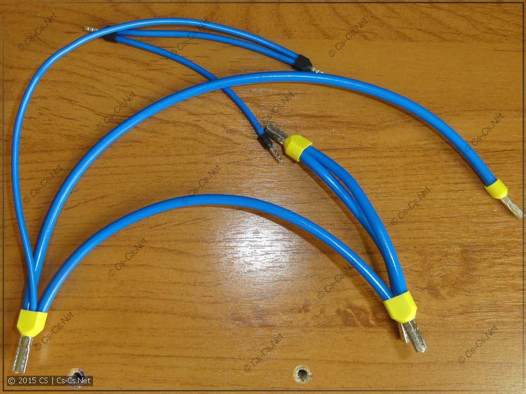
Here you can see the plus of assembling shields with wire with a stranded core (PuGV). There you can slip several sections under the tip at once and crimp it together, which you cannot do with a single core.
We twist this Cthulhu into the shield:

And after that we separate the phases. I came up with a cool layout of the panel in such a way that the VARs were inserted under the input switch. Therefore, the phase from it goes directly through the VAR, and then behind the DIN rails it rises to the UZMka. We connect the VARs to the UZMok, because they should show us the network voltage even if the UZM turns off - it’s from the VARs that we will determine what happened to the UZM and whether it’s time to turn off the input switch as soon as possible.
After this, we begin to connect the lines to the machines from the cross-modules. First, let's apply zero to the required machines.

And then, just like in the panel on the automatic machines, we will connect the phases from the automatic machines to the cross-module.

We will get a picture like this:
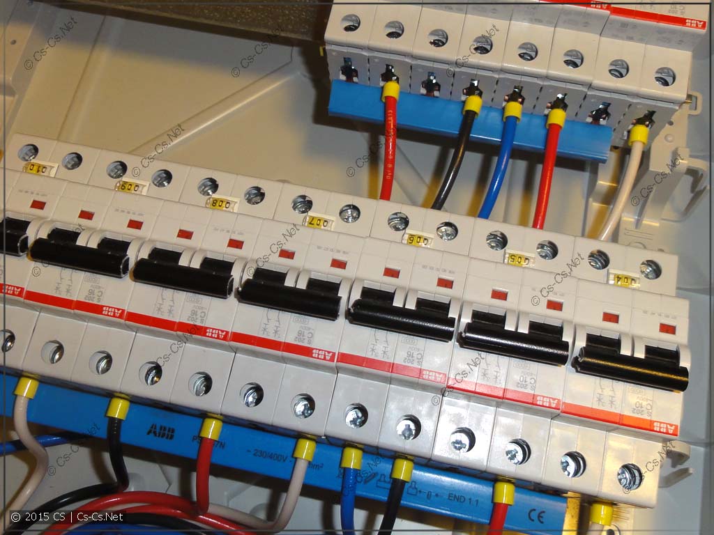
Compare it with the picture from the shield on automatic machines. Is there a difference for the end user connection? No! =)

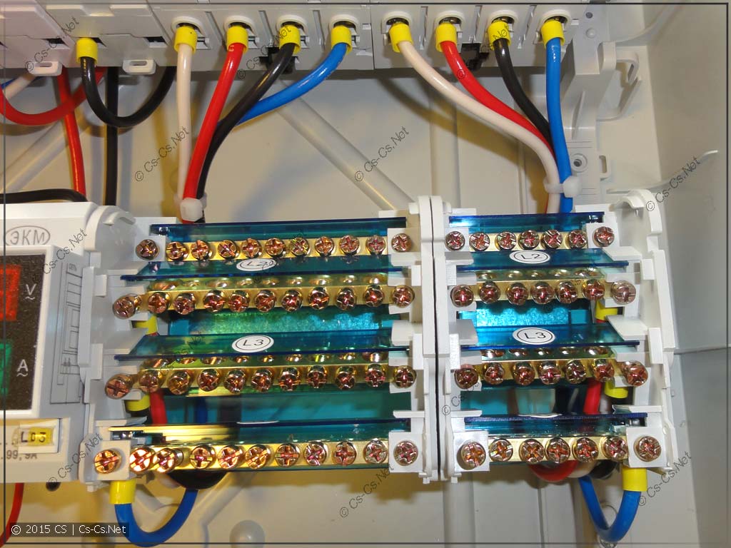
Well, a close-up photo of the cross-module. It is partially filled and selected with a reserve. If you need to switch something to another phase, just unscrew the wire from one bus bar and plug it into another.

This is what I ended up with. The DIN rails have room for new lines if they are needed. Everything inside the shield is quite free and clear.

And since the Mistral IP65 for 72 modules consists of two doors, it somehow happened naturally that one door is responsible for the input, and the other (which is not shown in the photo below) is for the group circuit breakers.

This panel has already been delivered to the customer and will probably be connected to them some weekend. While he still has the old input cable, one phase will come to the panel. But if you make a jumper on the input switch, then the new panel can be installed and connected immediately. And then, when the input cable is redone, the panel will be switched to three phases.
And to follow up, I’ll give you a couple more tips in the case of three-phase input and the development of panels for three phases.
Firstly, if your room is not a gazebo, where you only need to conduct light, always bring three phases entirely into each room. Don’t make poor decisions when you allocate one phase to the garage panel, another to the barn panel, and a third to the bathhouse panel. Lead three phases into each of these rooms so that you can easily count and switch three phases anywhere within your household.
That is, we start any panel of a shed or other room with a four-pole switch, where we supply all three phases. But only later, if you really need to make two lines there (for lights and sockets), we install a two-pole RCD and a couple of circuit breakers on one of the phases.
Secondly, when you consider the distribution of loads across phases, there is no need to invent any complications! Take it maximum load for each line and distribute these lines into phases so that the total amount of kilowatts for each is approximately equal. Even if you get 30 kW on each line, and you are allocated only 15. For example, like this:
Later, if you suddenly make a mistake, then it will be enough for you only later, in assembled shield, switch some of the lines on the cross-module. I will give an excerpt from my instructions for the shields:
In this panel, all main types of power (for example, non-switchable, main or non-priority) are routed to separate cross-modules (bus blocks L1-L2-L3-N). This facilitates panel layout and makes it easy to add new lines or change the load distribution among phases.
When designing a shield, the entire load is evenly distributed among the phases. If, when using the shield, it turns out that when some loads are turned on, the input circuit breaker knocks out due to overload, then you will need to change the phase distribution of some lines.
To change the phase distribution you only need a screwdriver. You need to open the cross-module, find the wire from the power line of the desired machine/dispenser, unscrew it from one phase busbar and screw it into any free hole in the other phase busbar. Usually on the wire there is a tube with a marking like “Lxx”, where “xx” is the number of the machine/dispenser that is powered from this wire.
How to understand what to rearrange from which and to which phase? This requires a little care and logical thinking. It is necessary to notice and remember which loads were turned on at the moment when the input circuit breaker turned off. After this, you need to refer to the documentation on the shield and see what phases they were in. If the panel was installed measuring instruments- then it will be immediately clear from them at which phase there was the heaviest load.
Suppose, for example, that in phase L1 we have hallway sockets, an oven and a water heater. IN the usual version everything was working fine, but suddenly they started turning on a powerful heater in the hallway. In practice, it may look like this: we are frying something, the heater is on, the water heater is turned on - and everything goes out. We turn the input machine back on, repeat the experiment, and observe. We remember that all the described loads are in phase L1.
This means that the solution will be to transfer one of these loads to some other phase. Which one you can choose either by logic like “the water heater is not used that often, let’s put it in the phase where the bathroom sockets are located” or empirically.
ATTENTION! You should not rearrange all the loads in a row and thoughtlessly. Thus, you can further disrupt their distribution, which will then be difficult to calculate and restore.
That's all! Assemble budget three-phase panels correctly. Remember that other people will use them, and that your shield should at all costs be convenient and understandable for these people, and not for some spherical abstract entities!
If you are interested in the information from this post and want to contact me (or order / ), then write me an email or call me at +7-926-286-97-35
. I answer to the name "Electroshaman".
I will harshly mock inattentive, stupid and arrogant salespeople and managers if they do not look into, but rather rush to call.