For existence electric current must exist inside the conductor electric field, and for the existence of a field in a conductor, a potential difference is necessary. The potential difference is called voltage. Moreover, the current is directed towards decreasing potentials (current, by agreement, is due to the movement of positive charges), and free electrons, accordingly, move in reverse side. Let's consider the movement of particles in a metal conductor.
Rice. 1. Movement of particles in a metal conductor
Let's say that at the ends of a certain section of the conductor there are potentials and , and .
In this case, the voltage across the section (or potential difference) is equal to .
It has been experimentally shown that the greater the voltage in the area, the greater the current passing through it.
The German scientist Georg Ohm conducted a series of experiments in 1826 and obtained a relationship that was later called Ohm's law.

Rice. 2. Georg Ohm
For different conductors, he built the so-called current-voltage characteristics - graphs of the dependence of current on voltage.

Rice. 3. Graph of current versus voltage
As a result, a linear relationship between current and voltage was discovered: by increasing the voltage, we also increase the current, this increase is directly proportional to: .
However, as can be seen from the graphs, the proportionality coefficient is different for each conductor. This meant that each conductor has a certain measure of current conductivity, and it is different for different conductors. This quantity was called electrical resistance. Resistance designation is R.
At the same voltage, conductors with less resistance will pass greater current.
Using experimental results, Ohm formulated a law, later called Ohm's law for a section of a chain. Ohm's law for a section of a circuit: The current strength for a homogeneous conductor in a section of a circuit is directly proportional to the voltage in this section and inversely proportional to the resistance of the conductor.
Resistance is main characteristic conductor. What is the nature of resistance? What determines the better or worse conductivity of current by conductors? The fact is that the electrons that move in the metal under the influence electric field, do not move in a homogeneous medium, they constantly interact with nodes crystal lattice metal and atoms of various impurities, slowing down. In the intervals between impacts they move uniformly accelerated.

Rice. 4. Movement of electrons in a metal conductor
Conductors can be solid, liquid, gaseous, plasma, and all of them have their own electrical resistance.
After explaining the mechanism of resistance, it becomes obvious that resistance depends only on the properties of the conductor, in particular, material, geometric dimensions and temperature. What is this dependence?
In this case, this is l - the length of the conductor;
S is the cross-sectional area of the conductor;
Ρ - resistivity.
The longer the conductor, the greater its electrical resistance, and the larger the cross-sectional area of the conductor, the lower the electrical resistance.
Resistivity- a tabular value characterizing the material’s ability to resist shows what resistance a conductor 1 meter long has, the cross-sectional area of which is 1 m 2.
Resistance unit - Ohm:
Unit resistivity: . By resistivity we can judge the material and how it can be used. All resistivities of materials known to us are collected in the table:

Rice. 5. Resistivity of metals
Based on conductivity, all materials are divided into three groups: conductors (resistivity about 10 -8 Ohm m), semiconductors (about 10 -4 -10 2 Ohm m) and insulators (about 10 8 -10 17 Ohm m).
Ohm's law for a section of a circuit is important for the calculation of electrical circuits.
In the next lesson we will look at how electrical resistances (resistors) are connected.
- Tikhomirova S.A., Yavorsky B.M. Physics (basic level) - M.: Mnemosyne, 2012.
- Gendenshtein L.E., Dick Yu.I. Physics 10th grade. - M.: Ilexa, 2005.
- Myakishev G.Ya., Sinyakov A.Z., Slobodskov B.A. Physics. Electrodynamics. - M., 2010.
Homework
- To make a 126 Ohm resistor, a nickel wire with a cross-sectional area of 0.1 mm 2 was used. What is the length of this wire?
- How will the resistance of a bare wire change if it is folded in half?
- What does resistance depend on?
- Internet portal Kakras.ru ().
- Internet portal Class-fizika.narod.ru ().
- Internet portal Uchifiziku.ru ().
- Internet portal Electromechanics.ru ().
Conductor resistance measurement: R =U/I→ 1 Ohm = 1 V/1 A.
Electrical resistance (R) is the property of an electrical circuit (conductor) to resist the electric current flowing through it, measured at constant voltage at its ends by the ratio of this voltage to the current.
Nature electrical resistance based on electronic ideas about the structure of matter: the “loss” of ordered movement of free charged particles in a conductor during their interaction with ions of the crystal lattice.
Dependence of the electrical resistance of a conductor on its length (rheostats), cross-section and material. Specific resistance of the conductor material: .
Question: Why does the resistance of a conductor depend on its length, cross-sectional area and material?
For wire = ![]() , where is the specific electrical conductivity.
, where is the specific electrical conductivity.
- (Ohm's law in differential form) - establishes a connection between quantities for each point of the conductor.
Demonstration of the dependence of conductor resistance on its temperature (low heat). Temperature coefficient of resistance.
Limits of applicability of Ohm's law.
IV. Tasks:
- Define electric charge, passing through the cross-section of a conductor with a resistance of 3 Ohms with a uniform increase in voltage at the ends of the conductor from 2 V to 4 V for 20 s.
2. Determine the cross-sectional area and length of an aluminum conductor if its resistance is 0.1 Ohm and its mass is 54 g.
Questions:
1. Explain that the resistance of a wire depends on its material, length and cross-sectional area.
2. How to cut a piece of wire with a resistance of 5 ohms?
3. Length copper wire doubled by stretching. How has her resistance changed?
4. Why does the resistance of human skin depend on its condition, contact area, applied voltage, and duration of current flow?
5. Will the resistance of the tungsten filament of a 120 V electric lamp change if it is connected to a current source with a voltage of 4 V?
6. Dam height – electrical voltage, water flow from the hole at the base of the dam - current strength. Is this analogy a good one?
V. § 54 Ex. 10 No. 3
1. Propose a design and calculate the parameters of a rheostat (wire material, length, cross-sectional area), the resistance of which can be smoothly varied from 0 to 100 Ohms with a maximum electric current of up to 2 A.
2. How does the resistance of a wire change when it is stretched? Try to establish this relationship within the limits of elastic deformations. Propose a design and calculate the parameters of a device (strain gauge) designed to measure mechanical stress.
Additional Information: The tensoresistive effect is a change in the resistance of a material during deformation.(recently created materials from aluminum and silicon change their resistance upon impact by almost 900 times).
3. Propose a design and describe electrical diagram a device for establishing the dependence of the resistivity of the conductor on temperature (possibly with a rheostat).
4. Measure the resistivity of water at room temperature and at boiling temperature.
"Direct experience is always obvious, and from it to shortest time can benefit."
LABORATORY WORK No. 3 "MEASURING THE RESISTANCE OF CONDUCTOR MATERIAL"
OBJECTIVE: To teach students to measure the resistivity of conductor material with a given accuracy.
TYPE OF LESSON: laboratory work.
EQUIPMENT: Current source, laboratory ammeter and voltmeter, key, rheostat, student ruler, conductor on block, connecting wires, caliper (micrometer).
LESSON PLAN: 1. Introductory part 1-2 min
2. Introductory briefing 5 min
3. Completion of work 30 minutes
4. Homework assignment 2-3 min
II. Laboratory setup diagram on a blackboard. How to measure conductor resistance; cross-sectional area of the wire; conductor length?

Relative and absolute error when measuring resistivity:
![]()
III. Completing of the work.
§ 16. OMA'S LAW
The relationship between e. d. with, resistance and current strength in a closed circuit is expressed by Ohm's law, which can be formulated as follows: The current strength in a closed circuit is directly proportional to the electromotive force and inversely proportional to the resistance of the entire circuit.
The current in the circuit flows under the influence of e. d.s; the more e. d.s. source of energy, the greater the current in the closed circuit. The resistance of the circuit prevents the passage of current, therefore, than more resistance circuit, the lower the current.
Ohm's law can be expressed by the following formula:
where r is the resistance of the external part of the circuit,
r 0 - resistance of the internal part of the circuit.
In these formulas, the current strength is expressed in amperes, e. d.s. - in volts, resistance - in ohms.
To express small currents, instead of an ampere, a unit is used that is a thousand times smaller than an ampere, called a milliampere ( ma); 1 A - 1000 ma.
Resistance of the entire circuit:
If under the influence of e. d.s. in 1 V in a closed circuit a current of 1 flows A, then the resistance of such a circuit is 1 ohm, i.e. 1 ohm =
Ohm's law is valid not only for the entire circuit, but also for any section of it.
If a section of a circuit does not contain an energy source, then positive charges in that section move from points of higher potential to points of lower potential. The energy source expends a certain amount of energy maintaining a potential difference between the beginning and end of this section. This potential difference is called the voltage between the beginning and end of the section in question.
Thus, applying Ohm's law to a section of the circuit, we obtain:
Ohm's law can be formulated as follows: current strength in the area electrical circuit equal to the voltage at the terminals of this section divided by its resistance.
The voltage on a section of the circuit is equal to the product of the current and the resistance of this section, i.e. U = Ir.
From the expression of Ohm's law for a closed circuit we obtain
Where Ir. - voltage drop in resistance r., i.e. in the external circuit, or, in other words, the voltage at the terminals of the energy source (generator) U,
Ir 0 - voltage drop in resistance r 0., i.e. inside the energy source (generator); it defines part of e. d. s, which is spent on conducting current through internal resistance source of energy.
To measure the current in a circuit, a device called ammeter(milliammeter). Voltage, as mentioned above, is measured with a voltmeter. The symbol for ammeter and voltmeter is shown in Fig. 15, a. To turn on the ammeter, the current circuit is broken and at the break point the ends of the wires are connected to the ammeter terminals (Fig. 15, b). Thus, the entire measured current passes through the device; such an inclusion is called consistent. A voltmeter is connected to the beginning and end of a section of the circuit; this connection of a voltmeter is called parallel. The voltmeter shows the voltage drop in a given area. If the voltmeter is connected to the beginning 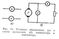 external circuit - to the positive pole of the energy source and to the end of the external circuit - to the negative pole of the energy source, then it will show a voltage drop in the entire external circuit, which will at the same time be the voltage at the terminals of the energy source.
The voltage at the terminals of the energy source (generator) is equal to the difference between the emf. and the voltage drop across the internal resistance of this source, i.e.
U=E – Ir 0(25)
If we reduce the resistance of the external circuit r, then the resistance of the entire circuit r + r 0 will also decrease, and the current in the circuit will increase. As the current increases, the voltage drops inside the energy source ( Ir 0) will increase, since the internal resistance r 0 energy source remains unchanged. Consequently, as the resistance of the external circuit decreases, the voltage at the terminals of the energy source also decreases. If the terminals of the energy source are connected with a conductor with a resistance almost equal to zero, then the current in the circuit I = .
This expression determines the maximum current that can be obtained in the circuit of a given source.
If the resistance of the external circuit is practically zero, then this mode is called short circuit.
For energy sources with low internal resistance, for example for electric generators (electric machines) and acid batteries, short circuit It is very dangerous - it can disable these sources.
A short circuit occurs quite often, for example due to a breakdown in the insulation of the wires connecting the receiver to the power source. Deprived of an insulating cover, metal (usually copper) linear wires, when in mutual contact, form a very small resistance, which, compared to the resistance of the receiver, can be taken equal to zero.
To protect electrical equipment from short circuit currents, various safety devices are used.
Example 1. Rechargeable battery with e. d.s. 42 V and internal resistance 0.2 ohm closed to an energy receiver having resistance 4 ohm. Determine the current in the circuit and the voltage at the battery terminals.
Example 2. The acid battery has e. d.s. 2 V and internal resistance - r 0 =0.05 ohm When an external resistance is connected to the battery, a current of 4 A. Determine the resistance of the external circuit.
Example 3. Generator direct current has an internal resistance of 0.3 ohm. Determine e. d.s. generator, if when you turn it on to the energy receiver with a resistance of 27.5 ohm voltage is set at the generator terminals to 110 V.
The current flowing in a closed circuit can be found from the following expression:
E, d.s. generator is equal to:
E=U+Ir=110+4 0.3=111.2 V.
Example 4. Battery of acid batteries with e. d.s. 220 V and internal resistance 0.5 ohm turned out to be short-circuited. Determine the current in the circuit.
![]()
Since for the type of battery given in the example, during a normal (ten-hour) discharge, the current is 3.6 A, then the current is 440 A is certainly dangerous for the integrity of the battery.
The connection of elements can be serial, parallel and mixed. Let's calculate the values for all three options. To calculate the values of these quantities, we apply Ohm’s law for a section of the circuit, a well-known law from school: I=U/R; U=I*R; R=U/I.
Simple circuit
Here Ohm's law for a section of a circuit considers the parameters of one consumer (be it a motor or a light bulb), which has resistance R. When electricity meets it, it does work. It is on this barrier that it is created potential difference. Let's take R=10 Ohm as a consumer.
By connecting a 9 V battery to R, we determine the current strength: I=U/R=9/10=0.9 A.
If known R, measuring I, you can find out how much drops across the resistor: I*R=0.9*10=9 B. I*R called voltage drop.
R can be calculated by measuring the volts across it and the amps passing through it. R=U/I=9B/0.9A=10.
It is often necessary to determine the power input R to be sure of its ability to dissipate the heat generated by electricity. Power consumption Р=I 2 *R=0.9 2 A*10=8.1 Wt. It is necessary to select a dissipation power no less than the calculated one, otherwise smoke will come out. In our case, we choose the standard 10 W, the smaller one is only 7.5 W.
Parallel connection
Now let's increase the difficulty of the section. Let's imagine consumers as R1 (10 Ohm) and R2 (5 Ohm). The value of R has changed and two paths have appeared. Only 9 V remained unchanged. 
To calculate the amperes coming to the branches, you need to know the total R. When parallel connection R is calculated using the formula 1/R=1/R1+1/R2+1/Rn... For two elements it looks like this: R=R1*R2/(R1+R2); R=10*5/(10+5)=3.3. Please note: in such a scheme, the resulting R is always less than the smallest.
We find I=9/3.3=2.7 A. The total R is also determined by measuring the total current (measurement showed 2.7 A). Then R=9/2.7=3.3.
Let's calculate each branch separately. All resistors are 9 V. Knowing Rn, we can calculate the amperes of the branch. For the first branch - I1=9V/R1=9/10=0.9 A. For the second - I2=9V/R2=9V/5=1.8. Important detail: the sum of the currents of all branches is equal to the total current. From here, I1=I-I2. The values of R1 and R2 are determined based on the amperes flowing into them and the connected volts: R1=9V/I1 etc.
Now let's see how the law responds to
Serial connection of load.
To find the current in a series circuit, you need to know how many ohms are in it? For a given section R we find this: R=R1+R2; R=10+5=15. We define I=U/R; I=9/15=0.6 A. Now let's take an interest in the voltage drop across the resistors. On R1 - U1=I*R1=0.6*10=6 V.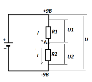
Look: 6 V has dropped on R1, and the total is 9 V. This means that 3 V should remain on R2 (U2=9B-6B=3B). Let's check the law: U2=I*R2=0.6A*5=3 V. That's right.
Along the way, we learned the value of the potential at point A relative to the minus supply - 3 V. This circuit is called voltage divider: from one we get two, and both can be used to power other circuits. Of course, we need to take their input data into account, but that’s for another story, although we also cannot do without Ohm’s law for a section of the circuit.
Mixed load connection
 A mixed connection is a combination of parallel and serial. For calculations, the same algorithm is used that was discussed in the previous versions. You just need to divide the branches according to the appropriate options.
Ohm's law for a section of the circuit follows
Ohm's law for a complete circuit.
It requires inclusion in the calculations of parameters power supply. First, let's look at the features of the device. Rectifier, battery, galvanic cell (ordinary battery), photocell (base solar battery) - all sources have internal resistance. In the rectifier - the transformer windings and related ones, in the battery - the electrolyte and the degree of emission of the electrodes. 
Ever noticed how battery charging is controlled not by an ordinary voltmeter, but by a load plug? What is this fork for? The battery produces volts, but they are not fully supplied: part ( Ir- read below) falls on his internal barrier. The load fork is something like our studied circuit, which consists of a resistor and a voltmeter connected in parallel. itself is not capable of creating a drop in the internal resistance of the battery. Therefore, a low-resistance shunt is connected in parallel to it, creating Ir. This is how we can judge the completeness of charging. Measuring the charging of the battery only with a voltmeter, we will not get the required result, since the loss in the battery will not be taken into account.
What any generator is capable of producing is called electromotive force (EMF), and what came in electrical network — voltage. The quantities are related as follows: EMF=Ir+IR. r is the internal resistance of the source, the remaining values are already known to us. U got from here: U=EMF-Ir. These two formulas define Ohm's law for the complete circuit.
§ 2.4. Voltage on a section of the circuit. By voltage in a certain section of an electrical circuit we mean the potential difference between the extreme points of this section.
In Fig. 2.5 shows a section of the chain, the extreme points of which are indicated by letters A And b. Let the current I flows from a point A to the point b(from higher potential to lower). Therefore, the potential of the point A(φ a ) above the potential of point b( φ b ) by a value equal to the product of the current I for resistance R: φ a = φ b+ IR.
According to the definition, the voltage between points A And b U ab = φ a - φ b .
Therefore, U ab = IR, i.e. the voltage across the resistance is equal to the product of the current flowing through the resistance and the value of this resistance.
In electrical engineering, the potential difference across the ends of a resistance is called either the voltage across the resistance or the voltage drop. Subsequently, the potential difference at the ends of the resistance, i.e., the product IR, we will call it the voltage drop.
The positive direction of the voltage drop in any section (the direction of reading this voltage), indicated in the figures by an arrow, coincides with the positive direction of reading the current flowing through a given resistance.
In turn, the positive direction of the current count I(current is an algebraic scalar) coincides with the positive direction of the normal to the cross section of the conductor when calculating the current using the formula, where δ is the current density; - element of cross-sectional area (for more details, see § 20.1).
Let's consider the question of voltage in a section of a circuit containing not only resistance, but also emf.

In Fig. 2.6, a, b shows sections of some circuits through which current flows I. Let's find the potential difference (voltage) between the points A And With for these areas. A-priory,
U ac = φ a - φ c (2.1)
Let us express the potential of a point A through the potential of the point With. When moving from a point With to the point b opposite to the direction of the EMF E(Fig. 2.6, a) point potential b turns out to be lower (less) than the potential of the point With, to the EMF value E: φ b = φ c- E. When moving from a point With to the point b according to the direction of the EMF E(Fig. 2.6, b) point potential b turns out to be higher (greater) than the potential of the point With, to the EMF value E: φ b = φ c+ E.
Since along the section of the chain without emf source current flows from a higher potential to a lower one, in both circuits Fig. 2.6 point potential A above point potential b to the value of the voltage drop across the resistance R: φ a = φ b+ IR. Thus, for Fig. 2.6, a
φ a = φ c- E+IR ,
U ac = φ a - φ c= IR - E , (2.2)
for fig. 2.6, b
φ a = φ c+ E + IR ,
U ac = φ a - φ c= IR + E. (2.2a)
Positive voltage direction U ac indicated by an arrow from A To With. According to the definition, U ca = φ c - φ a , That's why U ca= - U ac ,T. That is, a change in the alternation (sequence) of indices is equivalent to a change in the sign of this voltage. Therefore, voltage can be both positive and negative.