Agree, there are times when powering electronic trinkets requires a stable voltage that does not depend on the load, for example, 5 Volts to power a circuit on a microcontroller or, say, 12 Volts to power a car radio. In order not to turn the entire Internet upside down and assemble complex circuits using transistors, design engineers came up with the so-called voltage stabilizers. This phrase speaks for itself. At the output of such an element we will receive the voltage for which this stabilizer is designed.
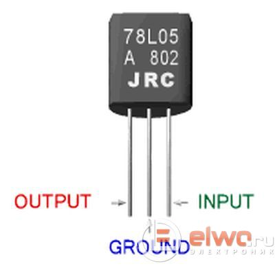
In our article we will look at three-terminal voltage stabilizers LM78XX family. The 78XX series are produced in metal cases TO-3 (left) and in plastic cases TO-220 (right). Such stabilizers have three terminals: input, ground (common) and output.

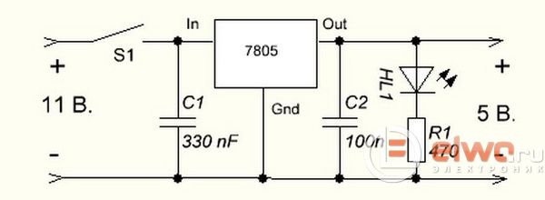
Instead of “XX”, manufacturers indicate the stabilization voltage that this stabilizer will give us. For example, a 7805 stabilizer will produce 5 Volts at the output, 7812 will produce 12 Volts, and 7815 will produce 15 Volts. It's very simple. And here is the connection diagram for such stabilizers. This circuit is suitable for all stabilizers of the 78XX family.

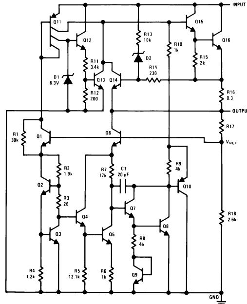
I think we can explain in more detail what is what. In the figure we see two capacitors that are sealed on each side. These are the minimum values of the condensers; it is possible, and even desirable, to supply a higher denomination. This is required to reduce ripple at both the input and output. For those who have forgotten what pulsations are, you can take a look at the article How to obtain a constant voltage from an alternating voltage. What voltage should be supplied to make the stabilizer work? To do this, we are looking for a datasheet for stabilizers and studying it carefully. And here is actually him. Look how many transistors, resistors, Schottky diodes and even a capacitor one stabilizer consists of! Just imagine, if we assembled this circuit from elements? =)
Let's move on. We are interested in these characteristics. Output voltage- output voltage. Input voltage- input voltage. We are looking for our 7805. It gives us an output voltage of 5 Volts. Manufacturers noted a voltage of 10 volts as the desired input voltage. But it happens that the output stabilized voltage is sometimes either slightly underestimated or slightly overestimated. For electronic trinkets, fractions of volts are not felt, but for precision (precision) equipment it is better to assemble your own circuits. Here we see that the 7805 stabilizer can give us one of the voltages in the range of 4.75 - 5.25 Volts, but the conditions must be met that the output current in the load will not exceed 1 Ampere. Unstabilized constant voltage can “fluctuate” in the range from 7.5 to 20 Volts, while the output will always be 5 Volts. This is the beauty of stabilizers.

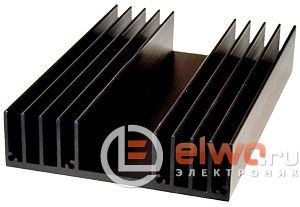
The power dissipation on the stabilizer can reach up to 15 Watts - this is a decent value for such a small radio component. Therefore, if the load at the output of such a stabilizer consumes a decent amount of current, I think it’s worth thinking about cooling the stabilizer. To do this, it must be placed on the radiator through KPT paste. The greater the output current, the larger the radiator should be. It would be generally ideal if the radiator was also blown by a cooler, like a PC in a computer.

Let's look at our ward, namely the LM7805 stabilizer. As you already understood, at the output we should get 5 Volts of stabilized voltage.

Let's assemble it according to the diagram
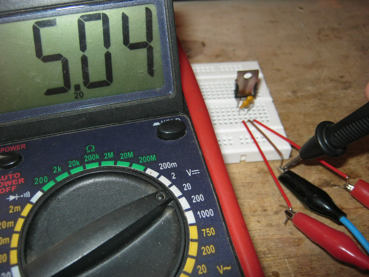
We take our Breadboard and quickly assemble the above-mentioned connection diagram. Two yellow ones are conders.

So, wires 1,2 - here we drive the unstabilized input DC voltage, remove 5 Volts from wires 3 and 2.
On the Power Supply we set the voltage in the range of 7.5 Volts and up to 20 Volts. In this case, I set the voltage to 8.52 Volts.

And what did we get at the output of this stabilizer? Oops - 5.04 Volts! This is the value we will get at the output of this stabilizer if we supply voltage in the range from 7.5 to 20 Volts. Works great!
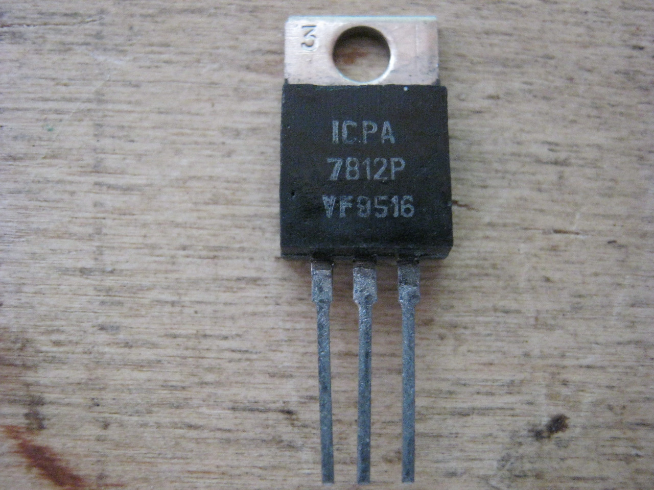
Let's check one more of our stabilizers. I think you have already guessed how many volts it is.
We assemble it according to the diagram above and measure the incoming voltage. According to the datasheet, you can apply an input voltage to it from 14.5 to 27 Volts. We set 15 Volts with kopecks.
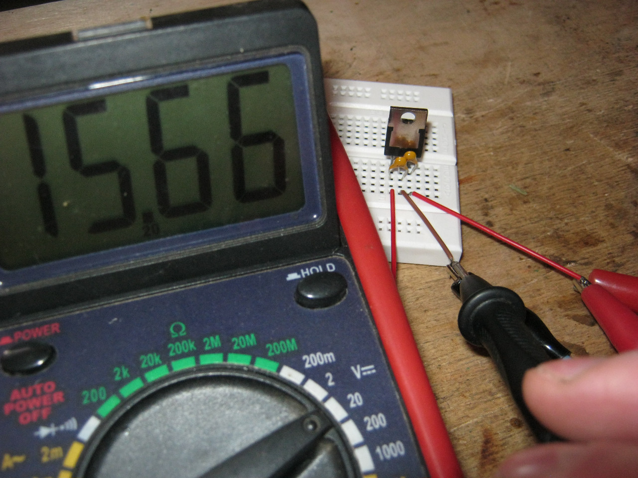
And here is the output voltage. Damn, some 0.3 Volt is not enough for 12 Volt. For radio equipment operating on 12 Volts this is not critical.

How to make a simple and highly stable power supply for 5, 9 or even 12 Volts? Yes, very simple. To do this, you need to read this article and install a stabilizer on the radiator at the output! That's all! The circuit will be approximately like this for a 5 Volt power supply:

Two electrolytic condenser filters to eliminate ripple, and a highly stable 5 Volt power supply at your service! To get a power supply for a higher voltage, we also need to get a higher voltage at the trance output. Strive for the voltage on Conder C1 to be no less than in the datasheet for the stabilizer being described.
To ensure that the stabilizer does not overheat and there is no need to install large radiators with airflow, if you have the opportunity, set the input voltage to the minimum voltage written in the datasheet. For example, for the 7805 stabilizer this voltage is 7.5 Volts, and for the 7812 stabilizer the desired input voltage can be considered a voltage of 14.5 Volts. This is due to the fact that the stabilizer will dissipate excess power on itself. As you remember, the power formula is P=IU, where U is voltage and I is current. Therefore, the higher the input voltage of the stabilizer, the greater the power consumed by it. And excess power is heating. As a result of heating, such a stabilizer may overheat and enter a protection state in which further work stabilizer stops.
All more electronic devices high-quality stable power is required without any voltage surges. The failure of one or another electronic equipment module can lead to unexpected and not very pleasant consequences. Use the achievements of electronics to your health, and don’t worry about powering your electronic trinkets. And don't forget about radiators ;-).
You can buy these integrated stabilizers cheaply as a whole set on Aliexpress at this link.
MICROCIRCUITS - VOLTAGE STABILIZERS
One of the important components of any electronic equipment is the supply voltage stabilizer. More recently, such units were built on zener diodes and transistors. The total number of stabilizer elements was quite significant, especially if it required the functions of adjusting the output voltage, overload protection and short circuit, limiting the output current at a given level. With the advent of specialized microcircuits, the situation has changed. Modern voltage stabilizer microcircuits are available for a wide range of output voltages and currents; they have built-in protection against overcurrent and overheating - when the microcircuit crystal heats up above permissible temperature it closes and limits the output current. In table 2 provides a list of the most common domestic market microcircuits linear stabilizers voltage to a fixed output voltage and some of their parameters, in Fig. 92 - pinout. The letters xx in the designation of a specific microcircuit are replaced by one or two numbers corresponding to the stabilization voltage in volts, for microcircuits of the KR142EN series - by the alphanumeric index indicated in the table. Microcircuits from foreign manufacturers of the 78xx, 79xx, 78Mxx, 79Mxx, 78Lxx, 79Lxx series may have different prefixes (indicate the manufacturer) and suffixes that determine the design (it may differ from that shown in Fig. 92) and temperature range. It should be borne in mind that information about power dissipation in the presence of a heat sink is usually not indicated in the data sheet, so some average values from the graphs given in the documentation are given here. Note also that for microcircuits of the same series, but for different voltages, the power dissipation values may also differ from each other. More detailed information about some series of domestic microcircuits can be found in the literature. Comprehensive information on microcircuits for linear power supplies is published in.
Typical scheme switching microcircuits to a fixed output voltage is shown in Fig. 93. For all microcircuits, the capacitance of capacitor C1 must be at least 2.2 μF for ceramic or tantalum and at least 10 μF for aluminum oxide
capacitors. The capacitance of capacitor C2 must be at least 1 and 10 µF for similar types of capacitors, respectively. For some microcircuits, the capacities may be smaller, but the indicated values guarantee stable operation for any microcircuits. In quality
In C1, a filter smoothing capacitor can be used if it is located no further than 70 mm from the microcircuit. You can find many connection diagrams for various options using microcircuits - to provide a higher output current, adjust the output voltage, introduce other protection options, use microcircuits as a current generator.
If a non-standard stabilization voltage or smooth adjustment of the output voltage is required, it is convenient to use three-pin adjustable microcircuits that support a voltage of 1.25 V between the output and the control pin. Their parameters are given in table. 3, and a typical connection diagram for positive voltage stabilizers is in Fig. 94.
Resistors R1 and R2 form an external adjustable divider included in the circuit for setting the output voltage Uout. which is determined by the formula:
where Ipotr is the microcircuit’s own current consumption, amounting to 50...100 μA. The number 1.25 in this formula is the above-mentioned voltage between the output and the control pin, which the microcircuit maintains in stabilization mode.
It should be borne in mind that, unlike stabilizers for a fixed output voltage, adjustable microcircuits
They don't work without load. The minimum value of the output current of such microcircuits is 2.5...5 mA for low-power microcircuits and 5...10 mA for high-power ones. In most applications, the current divider R1R2 is sufficient to provide the required load.
Basically according to the diagram in Fig. 94, you can also include microcircuits with a fixed output on
voltage, but their own current consumption is much higher (2...4 mA) and it is less stable when the output current and input voltage change.
To reduce the level of ripple, especially at high output voltages, it is recommended to include a smoothing capacitor C2 with a capacity of 10 μF or more. The requirements for capacitors C1 and C3 are the same as for the corresponding capacitors for microcircuits with a fixed output voltage.
Diode VD1 protects the microcircuit when there is no input voltage and its output is connected to a power source, for example, when charging batteries or from accidental short circuit of the input circuit when the capacitor SZ is charged. Diode VD2 serves to discharge capacitor C2 when the output or input circuit is closed and is not needed in the absence of C2.
The information provided serves for preliminary selection of microcircuits; before designing a voltage stabilizer, you should familiarize yourself with the complete reference data, at least in order to accurately know the maximum permissible input voltage, whether the stability of the output voltage is sufficient when the input voltage, output current or temperature changes. It can be noted that all parameters of the microcircuits are at a level sufficient for the vast majority of applications in amateur radio practice.
The described microcircuits have two noticeable disadvantages - a fairly high minimum required voltage between input and output - 2...3 V and restrictions on the maximum parameters - input voltage, power dissipation and output current. These shortcomings often do not play a role and are more than compensated by the ease of use and low price of the microcircuits.
Several designs of voltage stabilizers using the described microcircuits are discussed below.
Compensating positive voltage stabilizers of the popular “78xx” series were developed in 1976 by Texas Instruments. Subsequently, their modifications appeared (Table 6.3) and similar developments from other companies. Output voltages are standardized according to the series: 1.5; 1.8; 2.5; 2.7; 2.8; 3.0; 3.3; 4; 5; 6; 8; 9; 12; 15; 18; 24 V. Manufacturers differ in the first letters in the name, for example, L7812 (STMicroelectronics), KA7805 (Samsung), NJM78L03 (NJRCorporation), LM7805 (Fairchild), UTC7805 (UnisonicTechnologies). In the CIS countries, these stabilizers are known from the KR142ENxx series microcircuits.
An important nuance. The permissible voltage drop between the input and output of the stabilizer (£/In-out) depends on the load current. So, for example, for microcircuits of the “7805” series it is 1 V at a current of 20 mA and 2 V at a current of 1 A. In quick reference data, only the last parameter (2 V / 1 A) is usually indicated, and full load characteristics are given only in datasheet charts. Therefore, by carefully studying them, you can avoid unnecessary reinsurance.
All modern integrated stabilizers have protection against short circuits in the load, against thermal overheating of the crystal and against the operating point leaving the zone safe work.
In addition to fixed voltage stabilizers, there are integrated adjustable stabilizers. Their first samples were developed by Robert Dobkin in 1977 at National Semiconductor. Typical representatives of this direction are the “317” series microcircuits, the output voltage of which is determined by a divider on two resistors.
In Fig. 6.6, a...p shows circuits of adjustable and unregulated integrated positive voltage stabilizers.

Rice. 6.6. Circuits of compensating integrated positive voltage stabilizers (beginning):
a) typical circuit diagram for switching on an integrated stabilizer DAL The “78Lxx” series of microcircuits is ideal for simple amateur designs containing an MK and having a current consumption of up to 100 mA. The short circuit protection built into DA1 limits the output current to 0.1...0.2 A, which in many cases saves the MK in case of an accident. The input voltage is filtered by elements L1, C1, C2, and the inductor may be absent. Capacitors C1, C4 are installed close (0...70 mm) to the terminals of the stabilizer DA1 to prevent self-excitation of the latter. The capacitance of capacitor C2 must be several times greater than the capacitance of capacitor SZ, otherwise it is necessary to install a protective diode VD1 (shown in dotted lines). The main thing is that when the power is turned off, the output voltage +5 V decreases over time faster than the input voltage +6.5...+15 V (for this purpose, the capacitance of capacitor C2 is increased), otherwise the DA1 microcircuit may fail. If you are not sure, then it is recommended to install a similar diode in other similar circuits;
b) stabilizer DA1 (Maxim/Dallas) does not belong to the “78xx” series. It differs in name and functionality. In particular, the DA1 chip has an input for turning off the stabilizer (pin 4) and an input for smooth voltage regulation (pin 5). The MAX603 and MAX604 microcircuits are interchangeable and provide +5 and +3.3 V output, respectively;
c) LDO stabilizer on the DA1 chip with maximum current load 1 A (analogue K1184EN1). In the LM2940 family there are chips with an output voltage of 5; 8; 9; 10; 12; 15 V, and in the LP2950 family - with a voltage of 3.0; 3.3; 5 V;
d) UltraLDO stabilizer on a DA1 chip in an SMD package. Voltage UIN-out is no more than 0.12 V at a load current of 50 mA and no more than 7 mV at a load current of 1 mA. There are modifications of this stabilizer with output voltage according to the series: 1.5; 1.8; 2.5; 2.85; 3.0; 3.2; 3.3; 3.6; 3.8; 4.0; 4.7; 4.85; 5.0 V;
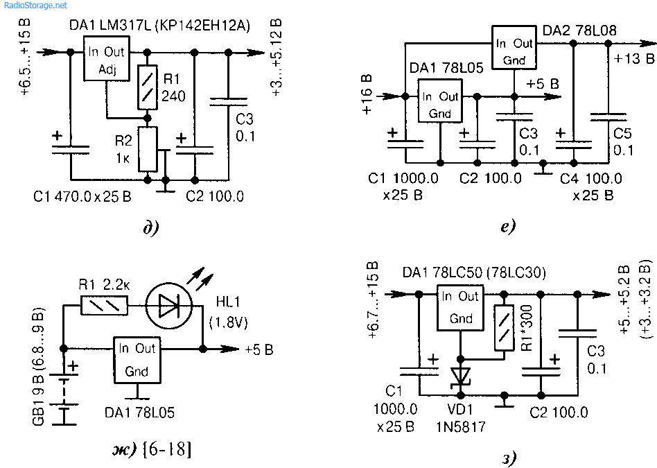
e) an adjustable voltage stabilizer on a DAI chip of the “317” series.
f) voltage +13 V is obtained by adding two voltages of stabilizers DAI and DA2
g) HL1 indicator lights up green at normal voltage battery/accumulator GB1 within 6.8...9 V. Below 6.8 V its glow stops, which is a signal to replace the battery or recharge the battery;
h) the standard method of increasing the output voltage of the DA1 stabilizer by 0.1...0.3 V. This may be required if the parameters of the DA I microcircuit are substandard or for testing the operation of the MC with increased power. Resistor R1 regulates within small limits the output voltage in the linear section of the current-voltage characteristic of diode VD1 (current 5... 10 mA). The RI resistor is not necessary if the DAI microcircuit of the “78LC05”, “78-L05” series is replaced with a similar one from the “7805” series, which has a current consumption through the GND pin within 3...8 mA;
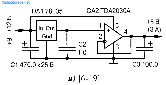
i) the DAI voltage stabilizer is supplemented by a current amplifier on the DA2 audio chip, which is used as a voltage follower with a load of up to 3 A. The power supply to the DA2 chip should be increased +9...+12 V, although not necessarily stabilized;
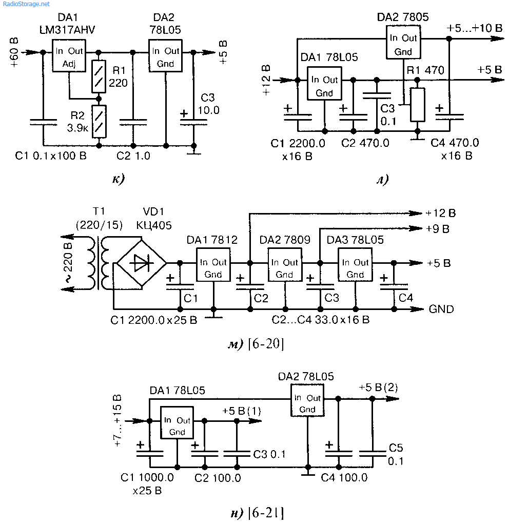
Rice. 6.6. Circuits of compensating integrated positive voltage stabilizers (continued):
j) The high input voltage of 60 V is first stepped down to 23 V (DA1) and then to 5 V (DA2). The voltage difference between the input and output of the DAI microcircuit should not exceed 40 V. With a large load current, it may be necessary to install DAI, DA2 microcircuits on radiators;
k) resistor RI smoothly adjusts the voltage in the upper, more powerful channel. If the middle terminal of resistor RI, as a result of rotation of its motor, is electrically connected to common wire, then the two channels will have identical voltages of +5 V. Stabilizers DAI, DA2 can have both the same and different output voltages;
m) the power supply with the code name “Step” consists of series-connected voltage stabilizers DA1...DA3. The load current, summed over three circuits + 12, +9 and +5 V, should not exceed the maximum permissible current for chip DA1
n) receiving two identical voltages from one common source +7...+15 V. This is useful, for example, for decoupling the analog and digital circuits of an MK or for separately powering a highly sensitive input amplifier;
![]()
Rice. 6.6. Circuits of compensating integrated positive voltage stabilizers (end):
o) obtaining three different stabilized voltages to power the processor core, as well as internal and external peripherals for new modern MKs. The FBI noise filter (Murata Manufacturing) has small dimensions. It can be replaced with a single-link LC filter using discrete elements;
n) obtaining a well-stabilized voltage of +5 V and a “quasi-stabilized” voltage of +2.8...+3.2 V. Diodes VD1...VD3 reduce the output voltage, but it will depend on the current flowing through them and temperature environment. There may be not three, but two diodes, both conventional and Schottky diodes. Resistor R1 serves as an initial load on the current in order to fix the operating point of the diodes on the steep vertical branch of the current-voltage characteristic, starting at 10 mA;
p) two-channel voltage regulator DA1 (STMicroelectronics) provides power to two output paths +5.1 and +12 V at once. The load current in each channel can be 0.75... 1 A.
The integrated voltage stabilizers of the KR142 series produced by the domestic industry make it possible to obtain stabilized voltages in a fairly large range using simple circuit methods - from a few volts to several tens of volts. Let's look at some circuit solutions that may be of interest to radio amateurs.
The KR142EN5A microcircuit is an integrated stabilizer with a fixed output voltage of +5 V. A typical connection circuit for this microcircuit has already been presented in the book (see.
rice. 105). However, by slightly changing the connection circuit, it is possible to build a stabilizer on the basis of this microcircuit with an adjustable output voltage in the range from 5.6 V to 13 V. The circuit is shown in Fig. 148.
The input of the integrated stabilizer (pin 17 of the DA1 chip) receives an unstabilized voltage of +16 V, and pin 8 receives a signal from the stabilizer output, regulated by a variable resistor R2 and current-amplified by transistor VT1. The minimum voltage (5.6 V) is the sum of the voltage between the collector and emitter of the fully open transistor, which is about 0.6 V, and the nominal output voltage of the integrated stabilizer in its typical configuration (5 V). In this case, the motor of the variable resistor R2 is in the upper position according to the diagram. Capacitor C1 smoothes out voltage ripples; capacitor C2 eliminates possible high-frequency excitation of the microcircuit. The load current of the stabilizer is up to 3 A (the microcircuit must be placed on a heat sink).
Microcircuits K142EN6A (B, V, D) are integrated bipolar voltage stabilizers with a fixed output voltage of 15 V. In this case, the maximum input voltage of each arm is 40 V, and the maximum output current is 200 mA. However, on the basis of this stabilizer it is possible to build a bipolar adjustable source of stabilized voltage. The diagram is shown in Fig. 149.
By changing the voltage at pin 2 of the integrated stabilizer, you can change the output voltage of each arm from 5 V to 25 V. The adjustment limits for both arms are set with resistors R2 and R4. It should be remembered that the maximum dissipation

The maximum power of the stabilizer is 5 W (of course, with a heat sink).
The KR142EN18A and KR142EN18B microcircuits are adjustable voltage stabilizers with an output voltage of 1.2...26.5 V and an output current of 1 A and 1.5 A, respectively. The regulator element of the stabilizer is included in the negative wire of the power supplies. The housing and pinout of stabilizers of this type are similar to the KR142EN5A microcircuit.
The microcircuits are equipped with a protection system against output current overload and overheating. The input voltage should be in the range of 5...30 V. The power dissipated by the microcircuit with a heat sink should not exceed 8 W. A typical connection diagram for KR142EN18A microcircuits (B) is shown in Fig. 150.
Under all operating conditions, the capacitance of the input capacitor C 1 should not be less than 2 μF. If there is a smoothing filter for the output voltage, if the length of the conductors connecting it to the stabilizer does not exceed 1 m, the input con

The output capacitor of the filter can serve as a stabilizer capacitor.
The output voltage is set by selecting the values of resistors R1 and R2. They are related by the relationship: Uout=Uout min(1+R2/R1),
in this case, the current flowing through these resistors must be at least 5 mA. The capacitance of capacitor C2 is usually chosen to be greater than 2 μF.
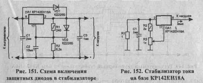
In cases where the total capacitance at the output of the stabilizer exceeds 20 μF, an accidental short circuit of the input circuit of the stabilizer can lead to failure of the microcircuit, since the capacitor voltage will be applied to its elements in reverse polarity. To protect the microcircuit from such overloads, it is necessary to turn on the protective diode VD1 (Fig. 151), which shunts it in the event of an emergency closure of the input circuit. Similarly, diode VD2 protects the microcircuit at pin 17 in cases where, according to operating conditions, the capacitance of capacitor C2 should be more than 10 μF with an output voltage of more than 25 V.
A current stabilizer can also be made on the basis of an integrated voltage stabilizer (Fig. 152). The output stabilization current is approximately equal to 1out = 1.5 B/R1, where R1 is selected within the range of 1...120 Ohms. Using variable resistor R3, you can regulate the output current.
If you look at the reference characteristics of the integrated voltage stabilizers KR142EN12A (B), you will notice that they have a lot in common with the KR142EN18A (B). The typical connection circuit for the KR142EN12A microcircuit is similar to the connection circuit
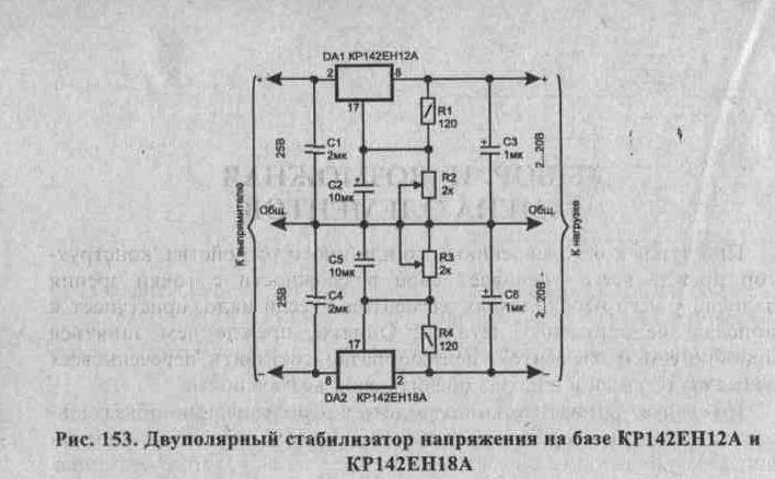
KR142EN18A, only the control element is included in the positive wire of the power source. Based on these microcircuits, it is easy to assemble a bipolar voltage stabilizer. Its diagram is shown in Fig. 153. No special comments are required here. To simultaneously change the voltage of the stabilizer arms, variable resistors R2 and R3 can be replaced with one, double one.
In this article we will look at the possibilities and methods of powering digital devices assembled by ourselves, in particular on. It's no secret that the pledge successful work of any device is its correct power supply. Of course, the power supply must be capable of delivering the power required to power the device and have an output electrolytic capacitor large capacity, to smooth out pulsations and it is desirable to be stabilized.
I will especially emphasize the latter, various unstabilized power supplies such as chargers from cell phones, routers and similar equipment are not suitable for powering microcontrollers and other digital devices directly. Since the voltage at the output of such power supplies varies depending on the power of the connected load. The exception is stabilized chargers with a USB output that produce 5 volts at the output, such as chargers from smartphones.
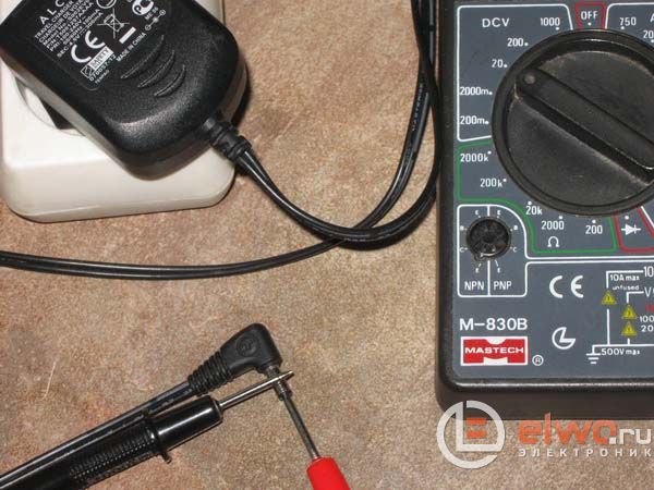
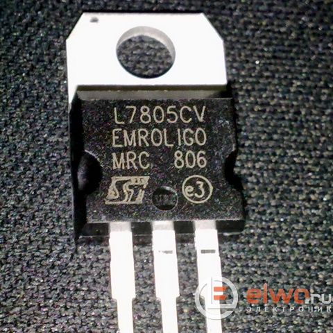
I think many people starting to study electronics, and those simply interested, were shocked by the fact: on a power adapter, for example from a set-top box Dandy, and any other similar unstabilized one can be written 9 volts DC (or D.C.), and when measured with a multimeter with probes connected to the contacts of the power supply plug on the multimeter screen, all 14, or even 16. Such a power supply can be used, if desired, to power digital devices, but a stabilizer must be assembled on a 7805 chip, or KREN5. Below in the photo is the L7805CV chip in the TO-220 package.
This stabilizer has easy scheme connections, from the microcircuit kit, that is, from those parts that are necessary for its operation, we only need 2 ceramic capacitor at 0.33 µF and 0.1 µF. The connection diagram is known to many and was taken from the Datasheet for the chip:
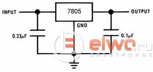
Accordingly, we apply voltage to the input of such a stabilizer, or connect it to the plus of the power supply. And we connect the minus to the minus of the microcircuit, and feed it directly to the output.

And at the output we get the stable 5 Volts we require, to which, if desired, if you make the appropriate connector, you can connect USB cable and charge your phone, mp3 player or any other device that can be charged from a USB port.
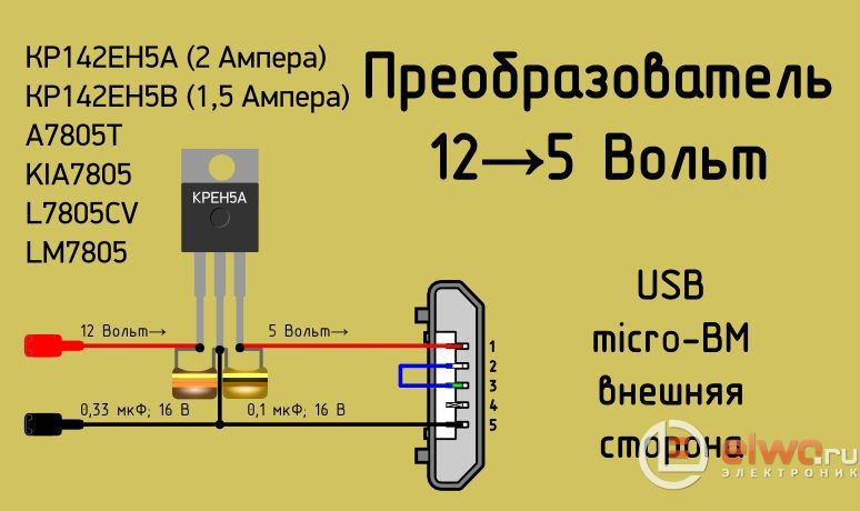
Stabilizer reduction from 12 to 5 volts - diagram
Automotive charger Everyone has long known about USB output. Inside it is arranged according to the same principle, that is, a stabilizer, 2 capacitors and 2 connectors.

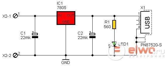
As an example for those who want to assemble such a charger with their own hands or repair an existing one, I will give its diagram, supplemented by a power-on indication on the LED:
The pinout of the 7805 chip in the TO-220 package is shown in the following figures. When assembling, you should remember that the pinout of microcircuits in different cases is different:
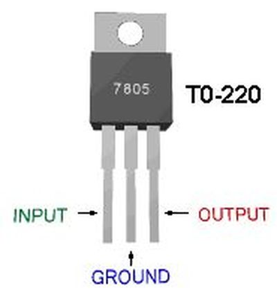
When purchasing a microcircuit in a radio store, you should ask for a stabilizer, like the L7805CV in the TO-220 package. This chip can operate without a heatsink at currents up to 1 ampere. If operation at high currents is required, the microcircuit must be installed on a radiator.
Of course, this microcircuit also exists in other packages, for example TO-92, familiar to everyone for its low-power transistors. This stabilizer operates at currents up to 100 milliamps. The minimum input voltage at which the stabilizer starts working is 6.7 volts, the standard is 7 volts. A photo of the microcircuit in the TO-92 package is shown below:

The pinout of the microcircuit in the TO-92 package, as already written above, differs from the pinout of the microcircuit in the TO-220 package. We can see it in the following figure, as it becomes clear from it that the legs are mirrored in relation to the TO-220:
Of course, stabilizers are produced for different voltages, for example 12 volts, 3.3 volts and others. The main thing is not to forget that the input voltage must be at least 1.7 - 3 volts more than the output voltage.

Chip 7833 - circuit diagram
The following figure shows the pinout of the 7833 stabilizer in the TO-92 housing. Such stabilizers are used to power devices on microcontrollers, displays, memory cards and other peripherals that require a lower voltage supply than 5 volts, the main power supply of the microcontroller.
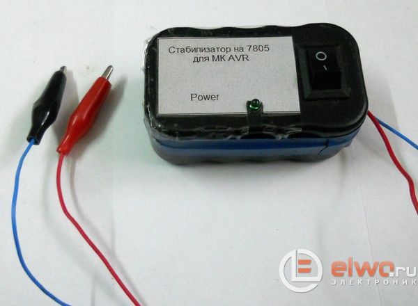
Stabilizer for power supply of MK
To power microcontroller devices assembled and debugged on a breadboard, I use a stabilizer in the case, as in the photo above. Power is supplied from an unstabilized adapter through a socket on the device board. His circuit diagram is shown in the figure below:
When connecting a microcircuit, you must strictly comply with the pinout. If the legs are confused, even one turn on is enough to disable the stabilizer, so you need to be careful when turning it on. The author of the material is AKV.