Voltage stabilizer circuits
To power devices that do not require high stability of the supply voltage, the simplest, most reliable and cheapest stabilizers are used - parametric ones. In such a stabilizer, the regulating element, when influencing the output voltage, does not take into account the difference between it and the specified voltage.
In the most in simple form A parametric stabilizer is a regulating component (zener diode) connected in parallel with the load. I hope you remember, because, unlike a diode, it is connected to the electrical circuit in the opposite direction, i.e., a negative voltage potential from the source follows the anode, and a positive voltage potential from the source follows the cathode. The principle of operation of such a stabilizer is based on the property of a zener diode to maintain a constant voltage at its terminals with significant changes in the strength of the current flowing in the circuit. A ballast resistance R, connected in series with the zener diode and the load, limits the flow of current through the zener diode if the load is turned off.
To power devices with a voltage of 5 V, a zener diode of type KS 147 can be used in this stabilizer circuit. The value of the resistor R is taken such that at the maximum input voltage level and the load is disconnected, the current through the zener diode does not exceed 55 mA. Since in operating mode the Zener diode and load current flows through this resistance, its power should be at least 1-2 W. The load current of this stabilizer should be in the range of 8-40 mA.
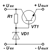
If the output current of the stabilizer is small for power supply, its power can be increased by adding an amplifier, for example based on a transistor.

Its role in this circuit is played by transistor VT1, the collector-emitter circuit of which is connected in series with the stabilizer load. The output voltage of such a stabilizer is equal to the difference between the input voltage of the stabilizer and the voltage drop in the collector-emitter circuit of the transistor and is determined by the stabilization voltage of the zener diode VD1. The stabilizer provides a current of up to 1 A in the load. Transistors such as KT807, KT815, KT817 can be used as VT1.
Five simple stabilizer circuits
Classic circuits that are repeatedly described in all textbooks and reference books on electronics.
Fig.1. Stabilizer according to the classical scheme without short-circuit protection in the load. 5B, 1A.
Fig.2. Stabilizer according to the classical scheme without short-circuit protection in the load. 12V, 1A.
Fig.3. Stabilizer according to the classical scheme without short-circuit protection in the load. Adjustable voltage 0..20V, 1A
The 5V 5A stabilizer is built on the basis of the article “Five-volt with a protection system,” Radio No. 11, 84, pp. 46-49. The scheme really turned out to be successful, which does not always happen. Easily repeatable.
The idea of thyristor load protection in case of failure of the stabilizer itself is especially good. If it (the stabilizer) burns out, then it’s more expensive to repair what it fed. The transistor in the current stabilizer VT1 is germanium to reduce the dependence of the output voltage on temperature. If this is not important, you can use silicon. The remaining transistors will fit any suitable power. If the regulating transistor VT3 fails, the voltage at the output of the stabilizer exceeds the response threshold of the Zener diode VD2 type KS156A (5.6V), the thyristor opens and short-circuits the input and output, and the fuse burns. Simple and reliable. The purpose of the adjustment elements is indicated in the diagrams.
Fig.4. Schematic diagram stabilizer with protection against short circuit in the load and thyristor circuit protection in case of failure of the stabilizer circuit itself.
Rated voltage - 5V, current - 5A.
RP1 - setting the protection response current, RP2 - setting the output voltage
The following stabilizer circuit is 24V 2A
All existing power supplies belong to one of two groups: primary and secondary power supply. Sources of primary power supply include systems that convert chemical, light, thermal, mechanical or nuclear energy into electrical energy. For example, chemical energy is converted into electrical energy by a salt cell or battery of cells, and light energy is converted into electrical energy by a solar battery.
The primary power source may include not only the energy converter itself, but also devices and systems that provide normal functioning converter Often, direct energy transformation is difficult, and then an intermediate, auxiliary energy transformation is introduced. For example, the energy of intra-atomic decay at a nuclear power plant can be converted into the energy of superheated steam that rotates the turbine of an electric machine generator, the mechanical energy of which is converted into electrical energy.
Secondary power sources include systems that electrical energy one type generates electrical energy of another type. For example, sources of secondary power supply are inverters and converters, rectifiers and voltage multipliers, filters and stabilizers.
Secondary power supplies are classified according to their rated operating output voltage. In this case, a distinction is made between low-voltage power supplies with voltages up to 100 V, high-voltage power supplies with voltages over 1 kV, and power supplies with average output voltages from 100 V to 1 kV.
Any sources of secondary power supply are classified according to the power Рн, which they are capable of delivering to the load. There are five categories:
micropower (PH< 1 Вт);
low power (1 W< Рн < 10 Вт);
medium power (10 W< Рн < 100 Вт);
increased power (100 W< Рн < 1 кВт);
high power (Рн > 1 kW)
Power supplies can be stabilized and unstabilized. In the presence of an output voltage stabilization circuit, stabilized sources have less fluctuation of this parameter compared to unstabilized ones. Keeping the output voltage constant can be achieved in various ways, however, all these methods can be reduced to the parametric or compensatory principle of stabilization. Compensating stabilizers have a feedback circuit to monitor changes adjustable parameter, but in parametric stabilizers there is no such feedback.
Any power source in relation to the network has the following basic parameters:
minimum, rated and maximum supply voltage or relative change in rated voltage up or down;
type of supply current: alternating or direct;
number of phases AC;
alternating current frequency and the range of its fluctuations from minimum to maximum;
coefficient of power consumed from the network;
the shape factor of the current consumed from the network, equal to the ratio of the first harmonic of the current to its effective value;
constancy of the supply voltage, which is characterized by constant parameters over time
In relation to the load, the power source can have the same parameters as in relation to the supply network, and is additionally characterized by the following parameters:
output voltage ripple amplitude or ripple factor;
load current value;
type of output current and voltage adjustments;
ripple frequency of the power supply output voltage, V general case not equal to the frequency of the alternating current supply network;
instability of output current and voltage under the influence of any factors that impair stability.
In addition, power supplies are characterized by:
efficiency;
mass;
overall dimensions;
temperature range environment and humidity
the level of noise generated when using a fan in the cooling system;
resistance to overloads and impacts with acceleration;
reliability;
duration between failures;
readiness time for work;
resistance to overloads in loads, and, as a special case, short circuits;
availability galvanic isolation between input and output;
availability of adjustments and ergonomics;
maintainability.
Parallel parametric stabilizer, series stabilizer based on a bipolar transistor. Practical calculations.
Good afternoon, dear Radio Amateurs!
Today on the website ““, in the ““ section, we will continue to review the article ““. Let me remind you that last time, while studying the power supply circuit for amateur radio devices, we focused on the purpose and calculation of the anti-aliasing filter:
Today we will look at the last element - the voltage stabilizer.
Voltage stabilizer - an electrical energy converter that allows you to obtain an output voltage that is within specified limits when the input voltage and load resistance fluctuate
Today we will look at two simple voltage stabilizers:
- ;
– .
Parallel parametric voltage stabilizer on zener diode
Semiconductor Zener diode - (another name is Zener diode) is designed to stabilize DC voltage power supplies. In the simplest circuit of a linear parametric stabilizer, it acts as both a source of reference voltage and a power control element. In more complex circuits, it is assigned only the role of a reference voltage source.
One of external views and the designation of the zener diode:

How does a zener diode work?
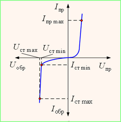
The voltage to the zener diode (unlike the diode) is supplied in reverse polarity (the anode is connected to the minus and the cathode to the plus of the power source - Uarr). When turned on in this way, reverse current flows through the zener diode - Iobr.
As the voltage increases, the reverse current grows very slowly (in the diagram, almost parallel to the axis Uarr), but at some voltage Uarr the zener diode junction breaks through (but the destruction of the zener diode does not occur at this moment) and the reverse current begins to flow through it significantly greater value. At this moment, the current-voltage characteristic of the zener diode ( CVC) goes down sharply (almost parallel to the axis Iobr) – stabilization mode begins, the main parameters of which are the minimum stabilization voltage ( Ust min) and minimum stabilization current ( Ist min).
With further increase Uarr The current-voltage characteristic of the zener diode again changes its direction - the stabilization mode ends, the main parameters of which are the maximum stabilization voltage ( Ust max) and maximum stabilization current ( Ist max). From this moment, the zener diode loses its properties and begins to heat up, which can lead to thermal breakdown of the zener diode junction and, accordingly, to its failure.
The stabilization mode of a zener diode can be within wide limits, therefore the documentation for zener diodes indicates the permissible minimum and maximum current values ( Ist min And Ist max) and stabilization voltages ( Ust min And Ust max). Within these ranges lie those selected by the manufacturer nominal values – Ist And Ust. The rated stabilization current is usually set by manufacturers at 25%-35% of the maximum, and the rated stabilization voltage as the average of the maximum and minimum.
For example, you can use the program “ “ and see with your own eyes what characteristics are given in reference books on zener diodes:
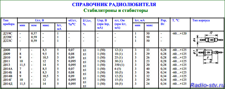
For example, a D814G zener diode:
- rated current stabilization (Ist) = 5 mA;
– rated voltage stabilization (Ust) = (from 10 to 12 volts) = 11 volts;
– maximum stabilization current (Ist max) = 29 mA.
We will need this data when calculating the simplest voltage stabilizer.
If you could not find the required native, Soviet, zener diode, then you can use, for example, a program to select a bourgeois analogue according to the required parameters:
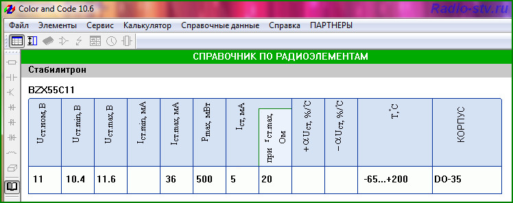
As you can see, the D814G zener diode can easily be replaced with an analogue - BZX55C11 (which has even slightly better characteristics)
Well, now let's look parallel parametric voltage stabilizer on a zener diode.
Parallel parametric voltage stabilizer on zener diode used in low-current devices (several milliamps) and is a voltage divider (on a resistor R– ballast resistor and zener diode VD– which acts as a second resistor) to the input of which an unstable voltage is supplied and the output voltage is removed from the lower arm of the divider. As the input voltage increases (decreases), the internal resistance of the zener diode decreases (increases), which allows the output voltage to be maintained at a given level. The difference between the input supply voltage and the stabilization voltage of the zener diode drops across the ballast resistor.
Let's consider the circuit of this (the simplest) voltage stabilizer:
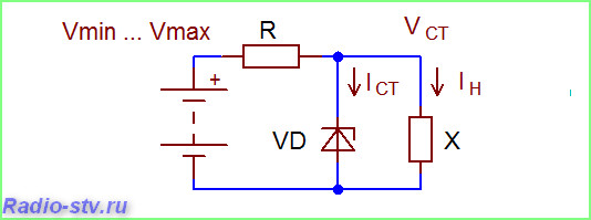
For normal operation schemes the current through the zener diode should be several times (3-10 times) higher than the current in the stabilized load. In practice, since the rated stabilization current of the zener diode is several times less than the maximum, it is allowed to assume in calculations that the load current should not exceed the rated stabilization current.
For example: the current consumed by the load is 10 mA, which means we need to select a zener diode such that its rated stabilization current is not less than 10 mA (it is better, of course, if it is larger).
Calculation of a parallel parametric voltage stabilizer using a zener diode
Given:
Uin– input voltage = 15 volts
Uout– output voltage (stabilization voltage) = 11 volts
Calculation:
1.
Using the reference book given above, we determine that the D814G zener diode is suitable for our purposes:
Ust(10-12v) = 11 volts
Ist max= 29 mA
Ist nominal = 5 mA
Based on the above, we determine that the load current should not exceed Ist nominal – 5 mA
2.
We determine the drop voltage across the ballast resistor (R) as the difference between the input and output stabilized voltage:
Upad=Uin – Uout=15-11= 4 volts
3.
Using Ohm's law, we determine the value of the ballast resistance R by dividing the drop voltage Udrop by Ist of the zener diode:
R= Up/Ist= 4/0.005= 800 Ohm
Since there are no resistors with a nominal value of 800 Ohms, we take the nearest higher value - R = 1000 Ohms = 1 kOhm
4.
Determining the power of the ballast resistor R:
Pres = Up*Ist= 4*0.005= 0.02 watts
Since not only the zener diode stabilization current flows through the resistor, but also the current consumed by the load, we increase the resulting value by at least 2 times:
Res= 0.004*2= 0.008 watts, which corresponds to the closest rating = 0.125 watts.
What to do if you haven’t found a zener diode with the required stabilization voltage.
In this case, you can apply series connection of zener diodes. For example, if we connect two D814G zener diodes in series, the stabilization voltage will be 22 volts (11+11). If we connect D814G and D810, we get a stabilization voltage of 20 volts (11+10).
Any number is allowed serial connection zener diodes of the same series (as in the example - D8**).
Series connection of zener diodes of different series is allowed only if the operating currents of the series chain fall within the certified stabilization current ranges of each series used.
What to do if, in the above example, the load current is, for example, not 5 but 25 mA?
You can, of course, leave everything as it is, since the maximum stabilization current (Ist max) of the D814G is 29 mA, the only thing you have to do is recalculate the power of the ballast resistor. But in this case, the zener diode will work at the limit of its capabilities and you will not have any guarantees that it will not fail.
But what if the load current is, for example, 50 mA?
Series voltage regulator on a bipolar transistor
Series voltage regulator on a bipolar transistor- This is essentially a parallel parametric stabilizer on a zener diode connected to the input of the emitter follower.
Its output voltage is less than the stabilization voltage of the zener diode due to the voltage drop at the base-emitter junction of the transistor (for silicon transistors - about 0.6 volts, for germanium transistors - about 0.25 volts), which must be taken into account when choosing a zener diode.
An emitter follower (also known as a current amplifier) allows you to increase the maximum current of the voltage stabilizer compared to a parallel parametric stabilizer on a zener diode in β (h 21e) times (where β (h21e)– current gain of a given transistor, the smallest value is taken).
Circuit of a series stabilizer based on a bipolar transistor :
Since this stabilizer consists of two parts - voltage reference(aka parallel parametric stabilizer on a zener diode) and current amplifier on a transistor (also known as an emitter follower), then the calculation of such a stabilizer is carried out similarly to the above example.
The only difference:
- for example, we need to get a load current of 50 mA, then we select a transistor with a gain β (h 21e) at least 10 ( β (h 21e)=Iload/Ist=50/5=10
– the power of the ballast resistor is calculated using the formula: Рres=Upad*(Ist+Iload)
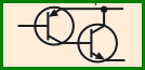
The load current can be increased several times more if you use a circuit with a composite transistor (two transistors connected according to a Darlington or Sziklai circuit):
 That's basically all.
Equipment: two breadboard panels, mounting conductors with lugs, milliammeter up to 10 mA, adjustable DC voltage source up to 10 V, digital voltmeter.
ATTENTION: installation of electrical circuits should only be carried out when the supply voltage is turned off on the breadboard panel.
Voltage stabilizer (current) is a device that automatically maintains voltage (current) on the consumer side (at the load) with a given degree of accuracy. Voltage stabilizers First of all, they are placed in power supplies after the rectifier. The more sensitive the device, the more accurate the measuring device, the higher the stability of the power supplies should be. Current stabilizers no less important than voltage stabilizers. Current sources are used to provide bias to transistors, as an active load of amplification stages. They are necessary for the operation of integrators and sawtooth voltage generators. Current stabilizers are also required, for example, in electrochemistry and electrophoresis.
Main destabilizing factors, causing change voltage (current) of the consumer are: fluctuations in the 220 V mains voltage, fluctuations in the frequency of the current in the network, changes in power consumed by the load, changes in ambient temperature, etc.
Stabilizers are divided depending on the type of voltage (current) for stabilizers variable voltage (current) and stabilizers permanent voltage (current). According to the operating principle stabilizers are divided into parametric And compensatory . Voltage (current) stabilization in parametric stabilizers is carried out due to the nonlinearity of the current-voltage characteristic (volt-ampere characteristic) of a nonlinear element (gas-discharge and semiconductor zener diode, stabilizer, field-effect or bipolar transistor, etc.). Compensating stabilizers are closed system automatic regulation with negative feedback. Depending on the method of switching on the control element Regarding the load resistance, stabilizers are divided into sequential And parallel . According to the operating mode of the control element stabilizers are divided into stabilizers with continuous regulation And pulse . In turn, pulse stabilizers are divided according to the control principle into pulse-width, pulse-frequency and relay.
The main parameters of DC voltage stabilizers that characterize the quality of stabilization are:
Stabilization coefficient K CT – the ratio of relative changes in input and output voltages (at constant output current):
![]() (1)
(1)
where DU IN and DU OUT are the increments of input and output voltages, respectively, U IN and U OUT are the values of the input and output voltages of the stabilizer.
Output impedance R OUT (or internal resistance r I) of the stabilizer is equal to the ratio of the increment in output voltage DU OUT to the increment in load current DI N at a constant input voltage U IN = const:
![]() (2)
(2)
Coefficient useful action (efficiency) – the ratio of the power at the output of the stabilizer to the power at the input.
Semiconductor parametric stabilizers (using zener diodes) are the simplest. They are characterized by relatively low stabilization coefficients (10–100), high output resistance (units and tens of ohms), and low efficiency.
Zener diode- This semiconductor diode, in which a section of electrical breakdown (avalanche or tunnel) on the reverse branch of the current-voltage characteristic is used to stabilize the voltage (Fig. 1). In the forward direction, the current-voltage characteristic of a zener diode is the same as that of any silicon diode. The breakdown voltage of the diode - the stabilization voltage of the zener diode U ST (from 3 to 200 V) depends on the thickness of the p-n junction or on resistivity diode base. Low voltage zener diodes (U ST< 6 В) изготавливаются на основе сильнолегированного кремния и в них происходит туннельный пробой. Высоковольтные стабилитроны (U СТ >6 B) are made on the basis of lightly doped silicon. Therefore, the principle of their operation is associated with avalanche breakdown.
In this laboratory work, Zener diodes D814A and 2S156A are studied. Their reference data is given in table. 1. Voltage stabilization is better the steeper the current-voltage characteristic curve (Fig. 1) and, accordingly, the lower the differential internal resistance of the zener diode. In addition, it should be noted that zener diodes with low voltage stabilization devices (with tunnel breakdown) have a negative temperature voltage coefficient (TCV), i.e. As the temperature increases, the stabilization voltage decreases. Zener diodes with avalanche breakdown have a positive TKN. There are also temperature-compensated zener diodes, made in one package in the form of a series connection of a zener diode with a positive TKN and a diode connected in the forward direction (which has a negative TKN).
Table 1
| Basic parameters | D814A | 2С156А |
| Stabilization voltage U ST, V | 7 – 8,5 | 5,6 |
| Stabilization voltage spread, % | – | ± 10 |
| Minimum stabilization current I ST m I n (current at which a stable breakdown occurs), mA | ||
| Maximum stabilization current I ST max (current at which the power dissipated on the zener diode does not exceed permissible value), mA | ||
| Differential internal resistance, Ohm | ||
| Temperature coefficient of stabilization voltage (ratio of relative change in stabilization voltage to absolute change in ambient temperature), % / °C | + 0,07 | ±0.05 |
| Maximum permissible forward current, mA | ||
| Maximum permissible power dissipation, W | 0,34 | 0,3 |
| Ambient temperature, °C | from minus 60 to +100 |
 Task 1.
1.1. Find zener diodes D814A and 2S156A on the breadboard panel, connected to current-limiting resistors 150 and 240 Ohms (Fig. 2).
1.2. Set the voltage to 10 V on the power supply. Connect a voltmeter to the D814A zener diode. Turn on the toggle switch on the layout panel. The current flowing through the zener diode causes it to heat up and change U CT. Does this zener diode have a positive or negative TKN? Using a clock, determine the time required to warm up the circuit. To do this, fill out the table. 2 voltage measurements on the zener diode at the moment the power is turned on and every minute. The warm-up time must be taken into account in the case when it is necessary to very accurately measure the voltage on the zener diode (up to thousandths (or hundredths) of a volt).
Table 2
1.3. Measure the reverse I-V characteristics of the zener diodes. To do this, it is necessary to measure the voltage on the zener diodes by applying a supply voltage from 1 to 10 V in steps of 1 V. The supplied voltage and the voltage on the zener diodes are measured with an accuracy of hundredths of a volt. The currents flowing through the zener diodes are calculated from the voltage drop across the current-limiting resistors. Fill in the table with the results of measurements and calculations. 3.
Table 3
| U PIT, V | D814A | 2С156А | ||
| U, V | I, mA | U, V | I, mA | |
| 1, | ||||
| 2, | ||||
| 3, | ||||
| 4, | ||||
| 5, | ||||
| 6, | ||||
| 7, | ||||
| 8, | ||||
| 9, | ||||
| 10, | ||||
| R D = Ohm | R D = Ohm |
1.4. According to the data presented in table. 3, construct experimental current-voltage characteristics of zener diodes (Fig. 3). Compare real stabilization voltages and minimum stabilization currents with reference data.
1.5.  In the working sections of the current-voltage characteristic, calculate the differential resistances and write them in the table. 3 and compare with reference data.
 Let us now consider the operation of a zener diode with a load R N. The circuit of the simplest parametric voltage stabilizer is shown in Fig. 4. As the input voltage U VX increases, as soon as the current through the zener diode becomes equal to I st min, the voltage on the zener diode stops increasing and becomes equal to U st.
A further increase in U VX only leads to an increase in the voltage drop across the current-limiting resistor R. Therefore, the voltage across the load R H is maintained unchanged.
Most often, a zener diode operates in a mode where the input voltage U VX is unstable and the load resistance R H is constant. For such a case, resistance R is usually calculated for the midpoint T of the volt-ampere characteristic of the zener diode (Fig. 1). If the voltage U VX changes from U min to U max, then R can be found using the following formula:
Where is the average input voltage; ![]() - average zener diode current; - load current. Voltage instability in this case is almost completely absorbed by resistor R. Fluctuations in the input voltage are smoothed out due to the low differential resistance of the zener diode.
- average zener diode current; - load current. Voltage instability in this case is almost completely absorbed by resistor R. Fluctuations in the input voltage are smoothed out due to the low differential resistance of the zener diode.
Second possible mode stabilization is applied in the case when U BX = = const, and R N varies from R n min to R n max. for such a mode, R can be determined from the average current values using the formula:
Where , ![]() ,
, ![]() .
.
The operation of the circuit in this mode can be explained as follows. Since the voltage drop across the resistor R is equal to U BX - U C T is constant, the current flowing through this resistor is also constant. This current is the sum of the zener diode and load currents. Therefore, if the current consumption of the load increases, then the current through the zener diode must decrease (so that their sum remains unchanged). If the load takes a lot of current from the zener diode, then the current through the zener diode becomes less than I c t min, and voltage stabilization is disrupted.
 Task 2.
2.1. Assemble the circuit shown in Fig. on the breadboard panel. 5, in which series-connected resistors with a resistance of 470 Ohms, 750 Ohms and the internal resistance of a milliammeter (100 Ohms) are used as a stabilizer load.
2.2. When connecting and disconnecting the load from the zener diode, check with a voltmeter that when the load is connected, the voltage U ST decreases. The voltage U ST also decreases with increasing load current. This can be shown by rotating the axis of a 470 ohm variable resistor. Thus, the load takes part of the current from the zener diode, and the operating point on the I-V characteristic of the zener diode moves up to the region of lower currents and lower stabilization voltages U ST (see Fig. 1 and Fig. 3).
2.3. Calculate the stabilization coefficient using formula (1) for the minimum load current (the higher the load current, the worse the voltage stabilization will be). To do this, change the input voltage from 9 V to 10 V (let DU IN = 10 V - 9 V = 1 V, and U IN = 9.5 V). The output voltage should be measured as accurately as possible (to thousandths of a volt), since the stabilization coefficient can reach several tens. When taking measurements, do not forget about the warm-up time of the circuit (see Table 2).
The voltage U OUT cannot be adjusted or set to a set value;
Zener diodes have a finite differential resistance, and therefore they do not always sufficiently smooth out input voltage ripples and the influence of changes in load resistance;
With a wide range of changes in load currents, it is necessary to choose zener diodes with high power scattering (with large maximum currents).
| |
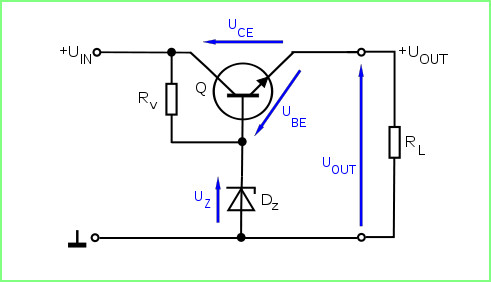
To obtain a more constant voltage across the load when the current consumed changes, a circuit is used (Fig. 6), in which the zener diode is separated from the load by an emitter follower. The zener diode current in such a circuit is relatively independent of the load current, since a small current flows through the base circuit of the transistor (less in h 21E than in the load). The transistor parameters (power limits, voltages and currents) are selected taking into account the load power.
If it is necessary to regulate the output voltage, then part of the reference (stabilized) voltage taken from the variable resistor motor is used. A circuit implementation of this feature is shown in Fig. 7.
Task 3.
3.1. Assemble voltage stabilizer circuits with zener diodes D814A and 2S156A (Fig. 6). Using a voltmeter, make sure that the output voltage is less than the voltage on the zener diode by the amount of the voltage drop across the emitter junction of the transistor (by » 0.6 V).
3.2. Using the resistances available in the circuit, calculate:
Maximum load power Р Н;
Power of resistors in the zener diode circuit Р R .
3.3. Fill in the table with the results of the calculations. 4.
Table 4
| D814A | 2С156А | ||
| R N, W | Р R, W | R N, W | Р R, W |
3.4. Assemble a voltage stabilizer circuit with an adjustable output voltage (Fig. 7) and check its operation.
There are a number of ways to increase the stabilization coefficient. In this case, the stabilizer circuit becomes more complex.
 Firstly, the zener diode can be powered through a current stabilizer (and not through a resistor), and then the voltage across the zener diode will practically not change.
Secondly, you can use a two-stage circuit (Fig. 8), the overall stabilization coefficient of which is equal to the product of the stabilization coefficients of individual cascades (links) and can reach several hundred.
Thirdly, you should choose other stabilizer circuits, for example, compensation type using transistor circuits and operational amplifiers.
Fourthly, you can use integral stabilizers voltage (microcircuits).
Let's consider stable current sources . Ideal source current has an infinitely large internal resistance R= ¥ and provides a current in the load R N that does not depend on the voltage drop across the load (on the load resistance).
The circuit of the simplest current source is shown in Fig. 9. Provided that R H<< R (т.е. U H << U), ток сохраняет почти постоянное значение приблизительно равное U/R.
The simplest resistive current source has significant disadvantages. In order to get a good approximation of the ideal current source, larger voltages must be used, and in doing so, more power is dissipated in the resistor. In addition, the current of such a source is difficult to control over a wide range using a voltage generated in another circuit node. If a significant current is required, then the voltage U (Fig. 9) must be selected at a large value. In order to provide I = 1 mA and R = 10 MOhm, a voltage of U = 10 kV must be applied. This condition can be overcome by requiring a large differential internal resistance (dU/dI), while the static internal resistance can be small. The output characteristic of the transistor (field-effect or bipolar) has this feature.
Any current source has a set of the same functional units: power source, control element, current sensor and load.
Circuit diagram of the current source shown in Fig. 10 is based on a common emitter circuit with negative current feedback. It works as follows. A base voltage U B > 0.6 V maintains the emitter junction in the open state: (for silicon transistors). The emitter current is:
Since for large values of the current gain h 21E, the emitter current is approximately equal to the collector current, the collector current (and this is the load current) is calculated using the same formula:
If you provide the possibility of changing the voltage at the base, you get an adjustable current source.
 Formula (3) is valid until the transistor goes into saturation mode. The current source transmits direct current to the load only up to a certain final voltage across the load, which cannot be greater than the supply voltage (see Fig. 10). Otherwise, the current source would be capable of generating infinite power. Therefore, for a current source, the operating range is determined by the fact that the transistor must be in the active operating mode.
Task 4.
4.1. Assemble a stable current source on a breadboard panel, shown in Fig. 11, while setting the 2 kOhm variable resistor in the load to a minimum (counterclockwise - all the way).
4.3. Check that the current of the voltage divider (resistors R1 and R2) exceeds 5–10 times the base current of the control transistor, which is approximately equal to I B = I K / h 21E, where the gain of the transistor h 21E is taken equal to 50.
I DIVIDER = mA, I B = mA. This condition is necessary so that when the load current changes (and, consequently, the base current flowing through resistor R1), the voltage at the base remains practically unchanged.
4.4. Using resistor R2 = 1 kOhm, set the load current to 5–7 mA. By rotating the axis of the 2 kOhm variable load resistor, make sure that an almost stable current flows through the load, however, in the extreme right position of the resistor axis (clockwise), the current decreases sharply. Why?
 4.5. Assemble the current stabilizer circuit shown in Fig. on a breadboard panel. 12, in which a zener diode is used to set the voltage at the base of the transistor. Theoretically calculate the zener diode current (I ST = mA) and load current (I H = mA). Experimentally check the load current using a milliammeter (I N EX = mA).
This article will discuss DC voltage stabilizers on semiconductor devices. The simplest circuits of voltage stabilizers, the principles of their operation and calculation rules are considered. The material presented in the article is useful for designing sources of secondary stabilized power.
Let's start with the fact that in order to stabilize any electrical parameter there must be a circuit for monitoring this parameter and a circuit for controlling this parameter. For stabilization accuracy, it is necessary to have a “standard” with which the stabilized parameter is compared. If during the comparison it turns out that the parameter is greater than the reference value, then the tracking circuit (let's call it the comparison circuit) gives a command to the control circuit to “reduce” the value of the parameter. And vice versa, if the parameter turns out to be less than the reference value, then the comparison circuit gives a command to the control circuit to “increase” the value of the parameter. All automatic control schemes for all devices and systems that surround us, from an iron to a spacecraft, operate on this principle; the only difference is in the method of monitoring and controlling the parameter. A voltage stabilizer works in exactly the same way.
The block diagram of such a stabilizer is shown in the figure.
The work of the stabilizer can be compared to regulating water flowing from a tap. A person approaches the tap, opens it, and then, watching the flow of water, adjusts its flow up or down, achieving the optimal flow for himself. The person himself performs the function of a comparison circuit; the standard is a person’s idea of what the flow of water should be, and the control circuit is a water tap, which is controlled by a comparison circuit (a person). If a person changes his idea of the standard, deciding that the flow of water flowing from the tap is insufficient, then he will open it more. The voltage stabilizer is exactly the same. If we want to change the output voltage, then we can change the reference voltage. The comparison circuit, noticing a change in the reference voltage, will independently change the output voltage.
A reasonable question would be: Why do we need such a clutter of circuits if we can use a source of a “ready-made” reference voltage at the output? The fact is that the source of the reference (hereinafter referred to as the reference) voltage is low-current (low-ampere), and therefore is not capable of powering a powerful (low-impedance) load. Such a reference voltage source can be used as a stabilizer to power circuits and devices that consume low current - CMOS chips, low-current amplifier stages, etc.
The circuit diagram of the reference voltage source (low-current stabilizer) is shown below. At its core, it is a special voltage divider, described in the article, its difference is that a special diode is used as a second resistor - a zener diode. What is special about a zener diode? In simple words, a zener diode is a diode that, unlike a conventional rectifier diode, when a certain value of the reversely applied voltage (stabilization voltage) is reached, passes current in the opposite direction, and with its further increase, reducing its internal resistance, strives to keep it at a certain meaning.
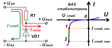 On the current-voltage characteristic (volt-ampere characteristic) of a zener diode, the voltage stabilization mode is depicted in the negative region of the applied voltage and current.
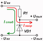
As the reverse voltage applied to the zener diode increases, it initially "resists" and the current flowing through it is minimal. At a certain voltage, the zener diode current begins to increase. Such a point in the current-voltage characteristic is reached (point 1 ), after which a further increase in voltage on the resistor-zener diode divider does not cause an increase in voltage by p-n Zener diode transition. In this section of the current-voltage characteristic, the voltage increases only across the resistor. The current passing through the resistor and the zener diode continues to increase. From point 1 , corresponding to the minimum stabilization current, up to a certain point 2 current-voltage characteristic corresponding to the maximum stabilization current, the zener diode operates in the required stabilization mode (green section of the current-voltage characteristic). After the point 2 In the current-voltage characteristic, the zener diode loses its “useful” properties, begins to heat up and may fail. Section from point 1 to the point 2 is a stabilization working section, in which the zener diode acts as a regulator.
Knowing how to calculate the simplest voltage divider on resistors, you can simply calculate the stabilization circuit (reference voltage source). As in the voltage divider, two currents flow in the stabilization circuit - the divider (stabilizer) current I st. and load circuit current I load. For the purpose of “qualitative” stabilization, the latter should be an order of magnitude smaller than the former.
For calculations of the stabilization circuit, the values of the zener diode parameters published in reference books are used:
- Stabilization voltage U st;
- Stabilization current I st.(usually average);
- Minimum stabilization current I st.min;
- Maximum stabilization current I st.max.
To calculate the stabilizer, as a rule, only the first two parameters are used - U st , I st., the rest are used to calculate voltage protection circuits in which a significant change in the input voltage is possible.
To increase the stabilization voltage, you can use a chain of series-connected zener diodes, but for this, the permissible stabilization current of such zener diodes must be within the parameters I st.min And I st.max, otherwise there is a possibility of the zener diodes failing.
It should be added that simple rectifier diodes also have the properties of stabilizing the reversely applied voltage, only the values of the stabilization voltages lie at higher values of the reversely applied voltage. The values of the maximum reverse applied voltage of rectifier diodes are usually indicated in reference books, and the voltage at which the stabilization phenomenon manifests itself is usually higher than this value and is different for each rectifier diode, even of the same type. Therefore, use rectifier diodes as a high-voltage zener diode only as a last resort, when you cannot find the zener diode you need, or make a chain of zener diodes. In this case, the stabilization voltage is determined experimentally. Care must be taken when working with high voltage.
The procedure for calculating a voltage stabilizer (reference voltage source)
We will calculate the simplest voltage stabilizer by considering a specific example.
Initial parameters required for the circuit:
1. Divider input voltage - U in(may or may not be stabilized). Let's assume that U in= 25 volts;
2. Output voltage stabilization - U out(reference voltage). Let's say that we need to get U outx= 9 volts. Solution:
1. Based on the required stabilization voltage, the required zener diode is selected from the reference book. In our case it is D814V.
2. From the table they find the average stabilization current - I st.. According to the table, it is equal to 5 mA.
3. Calculate the voltage dropped across the resistor - U R1, as the difference between the input and output stabilized voltage. U R1 = U inx - U out ---> U R1 = 25 – 9 = 16 volts
4. According to Ohm's law, this voltage is divided by the stabilization current flowing through the resistor, and the resistance value of the resistor is obtained. R1 = U R1 / I st ---> R1 = 16 / 0.005 = 3200 Ohm = 3.2 kOhm
If the obtained value is not in the resistive series, select the resistor with the closest nominal value. In our case, this is a resistor with a nominal value 3.3 kOhm.
5. Calculate the minimum power of the resistor by multiplying the voltage drop across it by the flowing current (stabilization current). Р R1 = U R1 * I st ---> Р R1 = 16 * 0.005 = 0.08 W
Considering that in addition to the zener diode current, the output current also flows through the resistor, therefore, choose a resistor with a power of at least twice the calculated one. In our case, this is a resistor with a power no less 0.16 W. According to the nearest nominal series(V big side) this corresponds to power 0.25 W.
That's the whole calculation.
As was written earlier, the simplest DC voltage stabilizer circuit can be used to power circuits that use low currents, but they are not suitable for powering more powerful circuits.
 One option for increasing the load capacity of a DC voltage stabilizer is to use an emitter follower. The diagram shows a stabilization cascade on a bipolar transistor. The transistor “repeats” the voltage applied to the base.
The load capacity of such a stabilizer increases by an order of magnitude. The disadvantage of such a stabilizer, as well as the simplest chain consisting of a resistor and a zener diode, is the impossibility of adjusting the output voltage.
The output voltage of such a stage will be less than the stabilization voltage of the zener diode by the value of the voltage drop by p-n base-emitter transition of the transistor. In the article, I wrote that for a silicon transistor it is equal to 0.6 ... 0.7 volts, for a germanium transistor - 0.2 ... 0.3 volts. Usually roughly calculated - 0.65 volts and 0.25 volts.
Therefore, for example, when using a silicon transistor with a zener diode stabilization voltage of 9 volts, the output voltage will be 0.65 volts less, i.e. 8.35 volts.
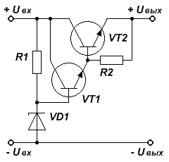 If instead of one transistor you use a composite circuit for connecting transistors, then the load capacity of the stabilizer will increase by another order of magnitude. Here, as in the previous circuit, one should take into account the decrease in output voltage due to its drop by p-n base-emitter transitions of transistors. In this case, when using two silicon transistors, the stabilization voltage of the zener diode is equal to 9 volts, the output voltage will be 1.3 volts less (0.65 volts for each transistor), i.e. 7.7 volts. Therefore, when designing such circuits, it is necessary to take this feature into account and select a zener diode taking into account losses at transistor transitions.
The resistance calculated in this way allows you to more effectively suppress the reactive component of the output transistor and fully use the power capabilities of both transistors. Don’t forget to calculate the required resistor power, otherwise everything will burn out at the wrong time. Resistor failure R2 can lead to failure of transistors and whatever you connect as a load. The power calculation is standard, described on the page.
How to choose a transistor for a stabilizer?
The main parameters for a transistor in a voltage stabilizer are: maximum collector current, maximum collector-emitter voltage and maximum power. All these parameters are always available in reference books.
1. When choosing a transistor, it is necessary to take into account that the passport (according to the reference book) maximum collector current must be at least one and a half times greater maximum current load that you want to receive at the output of the stabilizer. This is done in order to provide a margin of load current during random short-term load surges (for example, a short circuit). It should be taken into account that the greater this difference, the less massive the cooling radiator the transistor requires.
2. The maximum collector-emitter voltage characterizes the ability of the transistor to withstand a certain voltage between the collector and the emitter in the closed state. In our case, this parameter must also exceed at least one and a half times the voltage supplied to the stabilizer from the transformer-rectifier-power filter circuit of your stabilized power supply.
3. The rated output power of the transistor must ensure operation of the transistor in the “half-open” state. All the voltage that is generated by the “transformer-rectifier bridge-power filter” chain is divided into two loads: the actual load of your stabilized power supply and the resistance of the collector-emitter junction of the transistor. Both loads carry the same current because they are connected in series, but the voltage is shared. It follows from this that it is necessary to choose a transistor that, at a given load current, is capable of withstanding the difference between the voltage generated by the transformer-rectifier bridge-power filter circuit and the output voltage of the stabilizer. Power is calculated as the product of voltage and current (from a high school physics textbook).
For example: At the output of the “transformer-rectifier bridge-power filter” circuit (and therefore at the input of the voltage stabilizer) the voltage is 18 volts. We need to obtain a stabilized output voltage of 12 volts, with a load current of 4 amperes.
We find the minimum value of the required rated collector current (Iк max):
4 * 1.5 = 6 amps
We determine the minimum value of the required collector-emitter voltage (Uke):
18 * 1.5 = 27 volts
We find the average voltage that, in operating mode, will “fall” at the collector-emitter junction, and thereby be absorbed by the transistor:
18 - 12 = 6 volts
We determine the required rated power of the transistor:
6 * 4 = 24 watts
When choosing the type of transistor, it is necessary to take into account that the nameplate (according to the reference book) maximum power of the transistor must be no less than two to three times the rated power falling on the transistor. This is done in order to provide a power reserve for various load current surges (and therefore changes in the falling power). It should be taken into account that the greater this difference, the less massive the cooling radiator the transistor requires.
In our case, it is necessary to select a transistor with a rated power (Pk) of at least:
24 * 2 = 48 watts
Choose any transistor that satisfies these conditions, taking into account that the more the passport parameters are much larger than the calculated ones, the smaller the cooling radiator will be required (and may not be needed at all). But if these parameters are exceeded excessively, take into account the fact that the greater the output power of the transistor, the lower its transmission coefficient (h21), and this worsens the stabilization coefficient in the power source.
In the next article we will look at. It uses the principle of controlling the output voltage by a bridge circuit. It has less output voltage ripple than the "emitter follower", in addition, it allows you to regulate the output voltage within small limits. Based on this, it will be calculated simple circuit stabilized power supply.
For some electrical circuits and the circuits are quite sufficient for a conventional power supply that does not have stabilization. Current sources of this type usually consist of a step-down transformer, a diode bridge rectifier, and a filter capacitor. The output voltage of the power supply depends on the number of turns of the secondary winding on the step-down transformer. But as you know, the mains voltage of 220 volts is unstable. It can fluctuate within certain limits (200-235 volts). Consequently, the output voltage on the transformer will also “float” (instead of say 12 volts it will be 10-14, or so).
Electrical engineering, which is not particularly capricious to small changes DC supply voltage can get by like this a simple block nutrition. But more sensitive electronics can no longer tolerate this; it can even fail as a result. So there is a need for additional circuit stabilization of constant output voltage. In this article I provide a sufficient electrical circuit simple stabilizer constant voltage, which has a zener diode and a transistor. It is the zener diode that acts as a reference element that determines and stabilizes the output voltage of the power supply.
Now let's move on to the actual analysis electrical diagram a simple constant voltage stabilizer. So, for example, we have a step-down transformer with an AC output voltage of 12 volts. We apply this same 12 volts to the input of our circuit, namely to the diode bridge and filter capacitor. The diode rectifier VD1 makes constant (but intermittent) current from alternating current. Its diodes must be designed for the maximum current (with a small margin of about 25%) that the power supply can produce. Well, their voltage (reverse) should not be lower than the output voltage.
Filter capacitor C1 smooths out these voltage surges, making the DC voltage waveform smoother (though not ideal). Its capacity should be from 1000 µF to 10,000 µF. The voltage is also greater than the output. Please note that there is such an effect - alternating voltage after the diode bridge and filter capacitor, the electrolyte increases by approximately 18%. Therefore, in the end we will not get 12 volts at the output, but somewhere around 14.5.
 Now comes the DC voltage stabilizer part. The main functional element here is the zener diode itself. Let me remind you that zener diodes have the ability, within certain limits, to stably maintain a certain constant voltage (stabilization voltage) when turned back on. When a voltage is applied to the zener diode from 0 to the stabilization voltage, it will simply increase (at the ends of the zener diode). Having reached the stabilization level, the voltage will remain unchanged (with a slight increase), and the strength of the current flowing through it will begin to increase.
In our circuit of a simple stabilizer, which should produce 12 volts at the output, the zener diode VD2 is designed for a voltage of 12.6 (let’s put the zener diode at 13 volts, this corresponds to D814D). Why 12.6 volts? Because 0.6 volts will be deposited at the emitter-base transistor junction. And the output will be exactly 12 volts. Well, since we set the zener diode to 13 volts, the output of the power supply will be somewhere around 12.4 V.
 Zener diode VD2 (which creates the DC reference voltage) needs a current limiter that will protect it from excessive overheating. In the diagram, this role is played by resistor R1. As you can see, it is connected in series with the zener diode VD2. Another filter capacitor, electrolyte C2, is parallel to the zener diode. Its task is also to smooth out excess voltage ripples. You can do without it, but it will still be better with it!
Next in the diagram we see bipolar transistor VT1, which is connected according to a common collector circuit. Let me remind you, connection diagrams bipolar transistors of the common collector type (this is also called an emitter follower) are characterized by the fact that they significantly increase the current, but there is no voltage gain (even it is slightly less than the input, exactly by that same 0.6 volts). Therefore, at the output of the transistor we receive the constant voltage that is available at its input (namely, the voltage of the reference zener diode, equal to 13 volts). And since the emitter junction leaves 0.6 volts on itself, then the output of the transistor will no longer be 13, but 12.4 volts.
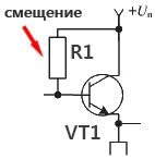 As you should know, in order for a transistor to start opening (passing controlled currents through itself along the collector-emitter circuit), it needs a resistor to create a bias. This task is performed by the same resistor R1. By changing its rating (within certain limits), you can change the current strength at the output of the transistor, and therefore at the output of our stabilized power supply. For those who want to experiment with this, I advise you to replace R1 with a tuning resistance with a nominal value of about 47 kilo-ohms. By adjusting it, see how the current strength at the output of the power supply changes.
Well, at the output of the simple DC voltage stabilizer circuit there is another small filter capacitor, electrolyte C3, which smoothes out ripples at the output of the stabilized power supply. Load resistor R2 is soldered in parallel to it. It closes the emitter of transistor VT1 to the minus of the circuit. As you can see, the scheme is quite simple. Contains a minimum of components. It provides a completely stable voltage at its output. To power many electrical equipment, this stabilized power supply will be quite enough. This transistor is designed for a maximum current of 8 amperes. Therefore, such a current requires a radiator that will remove excess heat from the transistor.
P.S. If we add a variable resistor with a nominal value of 10 kilo-ohms in parallel with the zener diode (we connect the middle terminal to the base of the transistor), then in the end we will get an adjustable power supply. On it you can smoothly change the output voltage from 0 to maximum (zener diode voltage minus the same 0.6 volts). I think such a scheme will already be in more demand.