Regions"
General manager
_______________»
______________________________
________________________________
"____" _________________ 2012
Method No. 1
TESTING
security forces cable lines
voltage up to 35 kV inclusive
Yuzhno-Sakhalinsk
Scope of application
Power cables are used for transmission electrical energy at high and low voltage.
In many cases, cable networks are used internally production premises, in factory areas and production sites.
The most important advantage cable lines in durability and almost complete independence from atmospheric influences.
The most common method is to lay cables directly into the ground due to its simplicity and low cost. The earthen trench for laying cables must have a depth of at least 800 mm. A soft cushion 100 mm thick is created at the bottom of the trench, which can be done either by adding soft soil or by loosening the soil of the trench itself. In this case, the depth of the cable must be at least 700 mm, and at the intersection of streets and squares - at least 1 meter. When entering a building, it is allowed to reduce the depth of cables to 500 mm from the ground surface in a section up to 5 meters long.
The trench is filled with excavated soil, which is first cleared of stones and debris. To protect cable lines with voltage from 1 to 20 kV from mechanical damage, the cable is covered on top concrete slabs or brick (but not silicate) in one row along the entire length across the cable, and lines up to 1 kV - only in places where frequent breaks are likely. Cables can be laid in asbestos-cement or ceramic pipes, also protecting against mechanical damage.
The route for laying the cable should be chosen as short as possible. If possible, avoid places with significant elevation changes, frequent excavations, aggressive soils, frequent intersections with pipelines, etc.
Inside buildings, cables are laid along walls and ceilings. It is also permitted to lay cables in pipes or ducts in the floor or interfloor ceilings, where they can be easily replaced in case of damage. For horizontal laying along walls, special supporting metal structures are used, wall shelves and profiles with cable hangers.
All cables must be subjected to periodic testing in accordance with this methodology.
Test object.
Power cables of any voltage consist of conductive cores, insulating and protective sheaths.
Conductors cables are made of copper or aluminum. According to the cross-sectional shape, the cores are made round, sector and segment. Depending on the number of current-carrying cores, power cables are one-, two-, three- and four-core. Domestic factories produce power cables of the following sections: 1.5; 2.5; 4; 6; 10; 16; 25; 35; 50; 70; 95; 120; 150; 185; 240; 300; 400; 500 and 600 mm2.
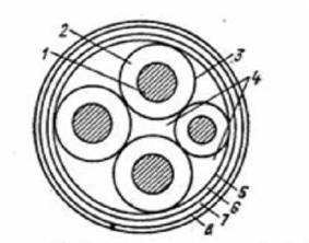
Power cables are manufactured for various voltages and, depending on this, have a certain range of standard cross-sections. For example, three-core cables for a voltage of 6-10 kV (Figure 1) are manufactured with a core cross-section from 10 to 240 mm2, for 10 kV - from 16 to 240 mm2, and for a voltage of 35 kV - from 70 to 150 mm2. Four-core cables (Figure 2) are manufactured only for voltages up to 1000V and have core sections from 1.5 to 185 mm2. The fourth core of a four-core cable, called zero, has a cross-section equal to the phase core or half as much. Currently everything greater distribution receive power cables for electrical installations with voltages up to 1000V with five separate cores, of which three are phase, one is zero working and one is zero protective.
Insulating shells cables are designed to isolate current-carrying conductors from each other (phase insulation) and from the ground (belt insulation). Insulating shells can be made of rubber, plastics and paper impregnated with oil rosin composition.
Protective shells cables serve to protect the insulating sheaths from destruction due to moisture penetration and from mechanical damage. The protective shells, which form a seal around the insulating shells, are made of lead, aluminum or plastics.
|
http://pandia.ru/text/78/450/images/image004_36.gif" realsize="326x139" width="326" height="139" align="left hspace=">Cables depending on the design of their protective shells can be laid in earthen trenches, along walls, ceilings and structures inside the building, in blocks, tunnels and channels. For example, in. interior spaces, as well as in channels and tunnels, cables with an aluminum, lead, plastic outer sheath, unarmored and armored, but without an outer jute sheath are laid. Power cables protected by armor and a jute sheath, as well as some cables with a plastic sheath, are laid in earthen trenches.
Get full textDetermined characteristics.
Insulation resistance measurement.
Insulation resistance is measured with a megohmmeter. For power cables with voltages up to 1000V, the insulation resistance must be at least 0.5 MOhm. For power cables with voltages above 1000V, the insulation resistance is not standardized.
Testing cable insulation with increased rectified voltage.
The test voltage value is taken in accordance with Table 1.
Table 1
Type of test | Test voltage (kV) for cable lines |
||
Paper insulated cables |
|||
Type of test | Plastic insulated cables |
||
Type of test | Rubber insulated cables |
||
* - trial increased voltage single-core cables with plastic insulation without armor (screens) laid in the air is not produced.
** - after repairs not related to cable reinstallation, the insulation is checked with a megohmmeter for a voltage of 2500V, and testing with increased rectified voltage is not performed.
For cables for voltages up to 10 kV with paper and plastic insulation, the duration of application of the full test voltage during acceptance tests is 10 minutes, in operation 5 minutes.
For cables with rubber insulation for voltage 6-10 kV, the duration of application of the full test voltage is 5 minutes.
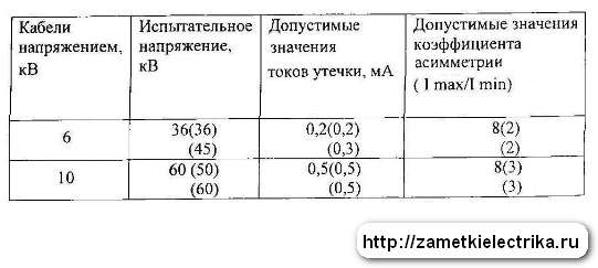
Permissible leakage currents depending on the test voltage and permissible values of the asymmetry coefficient when measuring leakage current are given in Table 2. The absolute value of the leakage current is not a rejection indicator. Cable lines with satisfactory insulation must have stable leakage current values. During testing, the leakage current should decrease. If there is no decrease in the leakage current, or if it increases or becomes unstable, the test is carried out until the defect is identified, but not more than 15 minutes.
Table 2.
Cable voltage (kV) | Test voltage (kV) | Valid values leakage current (mA) | Acceptable coefficient values asymmetry |
It is allowed to the technical manager of the enterprise during operation (M), based on local conditions, as an exception, to reduce the test voltage level for cable lines with a voltage of 6-10 kV to 4Un.
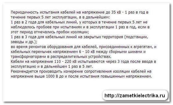
Frequency of testing during operation.
Cables with voltage 2-35kV:
a) once a year – for cable lines during the first 2 years after commissioning, and thereafter:
Once every 2 years - for cable lines for which during the first 2 years there were no emergency breakdowns or breakdowns during preventive tests, 1 time per year for cable lines on the routes of which construction and repair work was carried out and on which emergency breakdowns systematically occur isolation;
1 time every 3 years - for cable lines in closed areas (substations, factories, etc.);
during major repairs of equipment for cable lines connected to units, 6-10 kV cable jumpers between busbars and transformers in TP and RP;
b) it is permissible not to carry out the test:
for cable lines up to 100 meters long, which are outputs from switchgear and transformer substations to overhead lines and consist of two parallel cables;
for cable lines with a service life of more than 15 years, in which the specific number of failures due to electrical breakdown is 30 or more failures per 100 kilometers per year;
for cable lines subject to reconstruction or decommissioning in the next 5 years;
c) permitted by order technical manager enterprises establish other test frequency values and test voltages:
for supply cable lines for voltage 6-10 kV with a service life of more than 15 years with the number of connecting couplings more than 10 per 1 kilometer of length;
for supply cable lines for voltage 6-10 kV with a service life of more than 15 years, on which only types KVV and KVB terminations are installed and couplings locally manufactured, with a test voltage value of at least 4 Un and a frequency of at least 1 time in 5 years;
for cable lines with a voltage of 20-35 kV, during the first 15 years the test voltage should be 5 Un, and then 4 Un.
Cables for voltage 3-10 kV with rubber insulation:
a) in stationary installations – once a year;
b) in seasonal settings - before the start of the season;
c) after overhaul the unit to which the cable is connected;
Determination of the integrity of cable cores and phasing of cable lines.
Performed in operation after final installation, reinstallation of couplings or disconnection of cable cores. Phasing power cable after testing, it is necessary if it was a test of a new cable after installation, or an intermediate coupling was installed at the site of damage, etc. When carrying out preventive tests, a phasing check is not required.
Get full textTest and measurement conditions
Power cable lines are tested at positive temperatures environment, this is due to the fact that in the cold season, in frost, if there are frozen water particles in the cable mass or inside the insulation of a low-voltage cable, this will not be detected during testing, since ice is a dielectric.
The humidity of the surrounding air is important when conducting high-voltage tests, since condensation can lead to insulation breakdown and, accordingly, to failure of the equipment (both testing and being tested). Before carrying out high-voltage tests, cable funnels should be wiped free of dust, dirt and moisture. Atmospheric pressure does not have a special impact on the quality of the tests, but is recorded for entering data into the protocol.
Measuring instruments.
Cable insulation resistance is measured:
- on electrical wiring cables (including lighting circuits) with rated voltage up to 1000V - megohmmeters for voltage 1000V.
· on power cables with a rated voltage up to and above 1000V - megohmmeters for a voltage of 2500V.
Testing and measurement of cable leakage current at rectified voltage is carried out using test installations of the AID-70 or UKD-70 type.
The integrity of the cable cores is checked using multimeters or the ammeter-voltmeter method with a current supply not exceeding rated current cable line.
All instruments must be verified and testing facilities certified in the appropriate government agencies(TsSM).
Procedure for testing and measurements.
The circuit for measuring the insulation resistance of power cable lines above 1000V is shown in Figure 3. Measuring the insulation resistance of high-voltage cables is carried out on a completely disconnected cable.
Before checking, it is necessary to check the reliability of the grounding of the cable funnels, armor and connect a test grounding to the cable cores with special clamps(crocodiles). The second end of the cable remains free; the cores must be separated at a sufficient distance (approximately 150÷200 mm). If it is impossible to ensure the required distance between the conductors and from the cable conductors to grounded parts of the equipment, insulating caps or covers are put on the conductors. The resistance of the conductors is measured one by one with a megohmmeter, and a test grounding is installed on the conductors free from measurement.
100" height="40" style="vertical-align:top">
Figure 3. |
· for products without a metal sheath, screen and armor - between the current-carrying conductor and grounding.
· for products with a metal shell, screen and armor - between the conductive conductor and the metal shell or screen, or armor.
Electrical insulation resistance stranded cables, wires and cords should be measured:
· for products without a metal sheath, screen and armor - between each current-carrying conductor and the remaining conductors connected to each other and grounding.
· for products with a metal shell, screen and armor - between each conductive conductor and the remaining conductors connected to each other and the shell or screen, or armor.
In case of reduced insulation resistance of cables, wires and cords, which differs from the normative rules of PUE, GOST, it is necessary to carry out repeated measurements with disconnecting cables, wires and cords from consumer terminals and separating current-carrying conductors.
High voltage testing of cables
/text/categ/nauka.php" class="myButtonNauka">Get full text
After testing the high-voltage cable with increased voltage, it must be grounded for 15 minutes, and then measure the insulation resistance again with a megohmmeter.
Processing of data obtained during testing.
Primary records workbook must contain the following data:
date of measurements,
· name, type of equipment,
· nominal data of the test object,
· test results: insulation resistance before and after the test with increased voltage, test voltage, time of application of the test voltage, leakage currents at the beginning of the tests and before removing the test voltage, test circuit used.
All test data are compared with the requirements of the technical documentation and, based on the comparison, a conclusion is issued on the suitability of the cable for operation.
Safety measures during testing and environmental protection.
Before starting work you must:
· Obtain a work order (permit) to carry out work
· Prepare workplace in accordance with the nature of the work: make sure that the safety measures taken by the permitter are sufficient (when working according to orders) or take all safety measures yourself (when working according to orders).
· Prepare necessary tool and devices.
· When performing work, act in accordance with programs (methods) for testing electrical equipment, standard or for a specific connection. When conducting high-voltage tests on a stationary installation, proceed in accordance with the instructions.
Before completing the work you must:
· Clean the workplace, restoring the switching connections broken during work (if any).
· Hand over the work order (inform the manager or operational staff about the completion of work).
· Make a note in the workbook for subsequent work with the received data.
· Draw up a protocol for the work performed.
Trained employees from the Electrical Engineering Laboratory are allowed to carry out measurements using a megohmmeter. In electrical installations with voltages above 1000V, work is carried out according to orders, and in electrical installations with voltages up to 1000V - by order.
In cases where measurements with a megohmmeter are included in the scope of work, it is not necessary to stipulate these measurements in the work order or order. Measuring the insulation resistance with a megohmmeter should be carried out on disconnected current-carrying parts from which the charge has been removed by first grounding them. Grounding from live parts should be removed only after connecting the megohmmeter.
When measuring the insulation resistance of live parts with a megohmmeter, the connecting wires should be connected to them using insulating holders (rods). In electrical installations with voltages above 1000V, in addition, dielectric gloves should be used.
When working with a megohmmeter, touching the live parts to which it is connected is not allowed. After finishing work, the residual charge should be removed from live parts by briefly grounding them.
Carrying out work with the supply of increased voltage from an external source when testing power cable lines .
Personnel who have undergone special training and tested the knowledge and requirements contained in Section 5.1 of the Safety Rules are allowed to carry out testing of electrical equipment by a commission that includes specialists in testing electrical equipment with the appropriate electrical safety group.
Testing of electrical equipment, including outside electrical installations, carried out using a mobile testing unit, must be carried out on a regular basis. Testing during installation or repair of equipment must be specified in the “Assigned” line of the work order.
Testing of electrical equipment is carried out by a team, in which the work performer must have group IV, the team member must have group III, and the team member entrusted with security must have group II.
Mobile test units must be equipped with an external light alarm that turns on automatically when voltage is present at the terminal of the test unit, and sound alarm, briefly notifying about the application of test voltage.
Admission according to orders issued for testing and preparatory work to them, should be carried out only after the removal of other teams working on the equipment to be tested from the workplace and their delivery of work orders to the permitting authority. In electrical installations that do not have local personnel on duty, the work manager is allowed to keep the work crew after the removal of the team, having issued a break in work.
If necessary, a guard consisting of group II team members should be posted to prevent unauthorized persons from approaching the test facility, connecting wires and equipment being tested. Security team members must remain outside the fence and consider the equipment being tested to be energized. These workers can leave their post only with the permission of the work manager.
Get full textWhen testing a CL, if its opposite end is located in a locked chamber, switchgear compartment or indoors, a warning poster “Test. Life-threatening." If the doors and fences are not locked or the line being repaired is being tested with the cable cores cut on the route, in addition to hanging posters at the doors, fences and cut cable cores, a guard of team members with Group II or operational personnel on duty must be posted.
When placing the test setup and equipment under test in different rooms or on different areas RU is allowed to have team members with group III monitoring the state of insulation separately from the work contractor. These team members must be outside the fence and receive the necessary instructions from the work manufacturer before starting testing.
Removing the groundings installed during preparation of the workplace and interfering with the testing, and then installing them again, is allowed only on the instructions of the work manufacturer supervising the tests, after grounding the high voltage output of the testing installation.
Permission to temporarily remove groundings must be indicated in the “Separate instructions” line of the work order.
When assembling the test circuit, first of all, the protective and operational grounding of the test installation must be performed. The housing of the mobile testing unit must be grounded using a separate grounding conductor made of flexible copper wire with a cross section of at least 10 mm2. Before testing, check the reliability of the chassis grounding.
Before connecting the test installation to a 380/220V network, its high voltage output must be grounded.
The cross-section of the copper wire used in test circuits for grounding must be at least 4 mm2.
The connection of the test installation to a 380/220V network must be done through a switching device with a visible open circuit or through a plug located at the installation control location.
The switching device must be equipped with a device that prevents spontaneous switching on, or an insulating pad must be installed between the moving and fixed contacts of the device.
The wire or cable used to power the test electrical installation from a 380/220V network must be protected by fuses installed in this network or automatic switches. Representatives of the organization operating these networks must connect the mobile test unit to the network.
The connecting wire between the equipment under test and the test apparatus must first be connected to its high voltage ground terminal.
This wire should be secured in such a way as to avoid approaching (spiking) to live parts.
Connecting the connecting wire to a phase, pole of the equipment under test or to a cable core is permitted and disconnecting it is permitted as directed by the test supervisor and only after they are grounded, which must be done by turning on grounding knives or installing portable grounding connections.
Before each application of the test voltage, the work operator must:
- check the correct assembly of the circuit and the reliability of the workers and protective grounding; check whether all team members and workers assigned for security are in the places indicated to them, whether unauthorized people have been removed and whether test voltage can be applied to the equipment;
· warn the team about the supply of voltage with the words “Applying voltage” and, making sure that the warning is heard by all members of the team, remove the ground from the terminal of the test installation and apply voltage 380/220V to it.
From the moment the ground is removed from the terminal of the installation, the entire test installation, including the equipment under test and connecting wires, must be considered live and no reconnections are allowed in the test circuit or on the equipment under test.
From the moment voltage is applied to the terminal of the test installation, it is not allowed to be on the equipment being tested, or to touch the body of the test installation while standing on the ground, to enter and exit the mobile laboratory, or to touch the body of the mobile laboratory.
After completing the tests, the workman must reduce the voltage of the test installation to zero, disconnect it from the 380/220V network, ground the terminal of the installation and inform the team about this with the words “Voltage removed.” Only after this is it permissible to reconnect the wires or, if the test is completely completed, to disconnect them from the test installation and remove the guards.
After testing equipment with significant capacity (cables, generators), the residual charge must be removed from it using a special discharge rod.
Head of ETL ___________________
2. Frequency. Standards, testing schemes for cable lines.
2.1. Cable lines with voltages of 6, 10,20, 35 kV are tested:
- newly laid and after relaying, before backfilling and before switching on,
- in operation: according to schedule (scheduled tests), after repair, long-term shutdown, etc. (unscheduled tests).
2.2. Cable lines with voltage up to 1 kV are tested:
- newly laid - before turning on,
- after repair, steaming, pouring, etc. (unscheduled tests).
2.3. Cable lines 6, 10, 20 and 35 kV with paper insulation, including cable inserts and outlets air lines, are tested:
- a) once a year - for PKL and RKL, supplying especially responsible consumers and life support facilities of the city;
- b) once every 3 years - for other PCLs;
- c) once every 5 years for all other RCLs;
- d) it is allowed not to carry out the test:
- CL which are the outputs from the RP and TP to the overhead lines,
- CLs subject to decommissioning in the next 5 years,
2.4. Cable lines 10, 20 and 35 kV with cross-linked polyethylene insulation, including cable inserts, are tested:
- after cable line repairs,
2.5. Testing of protective plastic sheaths of 10-20 kV cables with cross-linked polyethylene insulation is carried out:
- before putting the cable into operation,
- after repairs to the main cable insulation,
- in cases of excavations in the security zone of the cable line and the associated possible violation of the integrity of the shells,
- periodically - 2.5 years after commissioning, then once every 5 years.
2.6. Testing PCL using testing laboratories or portable testing facilities, are carried out from the RP. If it is impossible to carry them out from the distribution center (no access, etc.), tests can be carried out from the power center. In this case, the application must indicate the reasons for the need to carry out these works from the food center.
2.7. Simultaneous testing of several series-connected distribution cable lines with disconnection is allowed power transformers, beams of parallel CLs, double or paired CLs.
2.8. Cable outlets and inserts are tested without being disconnected from the overhead line, and at the same time, the arresters installed on the overhead line must be disconnected.
2.9. The magnitude and duration of the test voltage applied to the cable conductors is indicated in Table No. 1.
Table No. 1
| Purpose and objects of testing | Line operating voltage (kV) | AC test voltage 0.1 Hz (kV) | Duration of application test. voltage 0.1 Hz (min) | Rectified current test voltage (kV) | The duration of the application is rect. test voltage (min) |
| 1. Paper insulated cable lines: | |||||
| 1.1. Before putting into operation (CLs are fully or partially made with a new cable). | Up to 1 | 6 | 10 | ||
| 6 | 36 | 10 | |||
| 10 | 60 | 10 | |||
| 35 | 175 | 10 | |||
| 1.2. In operation: | |||||
| - planned according to schedule and extraordinary, | Up to 1 | 2.5 kV (megaohmmeter) | - | ||
| 6 | 12 | 20 | 30 | 5 | |
| 10 | 18 | 20 | 50 | 5 | |
| 35 | 100 | 5 | |||
| - for cable lines supplying especially critical facilities, | 6 | 12 | 20 | 30 | 5 |
| 10 | 18 | 20 | 50 | 5 | |
| - for cable lines with a service life of more than 15 years, except for especially responsible ones, | 6 | 20 | 20 | 5 | |
| 10 | 20 | 40 | 5 | ||
| - for cable lines with a service life of more than 25 years, except for especially critical ones. | 6 | 12 | 20 | 18 | 5 |
| 10 | 18 | 20 | 30 | 5 | |
| 1.3. Before turning on, if the CL was off for more than 5 days. | 6 - 10 | UPK-01M | - | ||
| 2. Cable lines with plastic insulation: | |||||
| - newly laid, | up to 0.66 | 3,5 | 5 | ||
| 1 | 5,0 | 5 | |||
| - after renovation | up to 1 | 2.5 kV (megaohmmeter) | - | ||
| 3. Cable jumpers in RP and TP with paper-oil insulation | 6 | 12 or 10,5 50Hz |
10 10 |
20 | 10 |
| 10 | 18 or 17,5 50Hz |
10 10 |
30 | 10 | |
| 4. Cable lines and cable jumpers in RP and TP made of single-core cable with cross-linked polyethylene insulation, newly laid and after repair. | Up to 1 | Megaohmmeter 2.5 kV | |||
| 6 | 12 or 10,5 50 Hz |
30 (20 after repair) | |||
| 10 | 18 or 17,5 50 Hz |
30 (20 after repair) | |||
| 20 | 35 or 34,7 50 Hz |
30 (20 after repair) | |||
| 5. Plastic sheaths (hose) of cross-linked polyethylene cables, newly laid, after repairs and periodically. | From 10 and above | 5 | 10 | ||
2.10. To test cable lines with direct rectified voltage, test installations mounted on vehicles (see clause 7.1, diagram 1) and small-sized portable installations (see clauses 7.2., 7.4.-7.10.) are used.
2.11. Testing of cable lines with cross-linked polyethylene insulation is carried out with alternating voltage of super low frequency, which is generated special installations(see clauses 7.11 - 7. 14.), These installations can be made as stationary, mounted on a vehicle (clause 7.11), and as mobile, transported by any suitable by road transport(paragraph 712 -7.14).
2.12. To test the CL shell with cross-linked polyethylene insulation, testing installations - generators - are used. DC with a maximum output voltage of up to 5 kV (clause 7.15.) It is allowed to use high-voltage testing installations designed for testing CLs with paper-oil insulation, subject to the following conditions:
- The output voltage should be monitored using a display with a digital readout or a kilovoltmeter scale, where 5 kV is at least a quarter of the scale.
- Leakage current monitoring should be carried out using a microammeter, manually turning off the test installation when current values exceed more than 300 μA.
2.13. When testing insulation, voltage is applied in turn to each core (phase) of the cable line, while the other two, together with the shell, are grounded.
To reduce the total test time, when testing short (up to 1 km) cable lines with cross-linked polyethylene insulation made from single-core cables, it is possible, if the installation capacity allows, to combine all three cores and test them simultaneously. If a breakdown occurs during the test, repeat the phase test of each core to identify the damaged one.
2.14. During the testing of each phase of a paper-insulated CL, periodically and at the last minute of the test, the leakage current is measured according to the microammeter reading.
If during testing the leakage current increases or current surges appear, the test duration should be increased by 2 times. In the future, if the cable line cannot be brought to breakdown at a given test voltage, then it is tested with increased voltage according to the standards for new cables - 6 times the voltage for 10 minutes each phase. If the cable line has passed this test without breakdowns, then it can be included in the work by decision of the chief engineer of the district.
When testing CLs with cross-linked polyethylene insulation, leakage current monitoring may not be carried out, however, during the test it is necessary to monitor the value of the test voltage using a kilovoltmeter. The maximum deviations of the kilovoltmeter needle during periodic changes of polarity in both directions relative to zero (see clauses 7.9.1. - 7.9.5), indicating the set value of the test voltage, should not decrease by more than 15% during the test.
If such a decrease is recorded, the test time should be increased to 1 hour. If during this time the cable line has passed this test without breakdowns, it can be put into operation.
2.15. A cable line with voltages of 6, 10, 20 and 35 kV is considered suitable for operation if it has withstood the test voltage for the time specified in clause 2.9. of this instruction (taking into account the additions under clause 2.14.). For a cable line made of 3 single-core cables with cross-linked polyethylene insulation, the test results of the protective sheath are additionally taken into account, which must withstand the DC rectified voltage test in accordance with the standards of clause 5 of Table No. 1.
2.16. After a repair test, a cable line with a voltage of up to 1 kV is considered to have passed the test if the insulation resistance, measured with a 2.5 kV megohmmeter, is not lower than 0.5 mOhm. At lower resistance values, when testing with a 2.5 kV megohmmeter does not lead to breakdown of the CL insulation, the CL should be tested using a burning installation. If during testing it is not possible to reduce the insulation resistance, the cable line, by decision of the chief engineer of the district, can be included in the work.
2.17. Testing and switching on of a 6 - 35 kV cable line after repair should be carried out within the time limits specified in clause 6 of the “Regulations on the organization and conduct of emergency restoration work at OJSC Moscow Electric Grid Company”.
2.18. When testing the sheath of single-core cables with cross-linked polyethylene insulation, the test voltage is applied between the cable shields and the ground. To do this, the screens of each of the cable line cores, in order to avoid mutual electrical contact between themselves and the grounding loop, are disconnected from the grounding loop on both sides of the line and separated in different directions. For cable line screens of 6-10 kV, if they are combined along construction lengths (cable screens of 20 kV and above are not combined), it is enough to ensure that at both ends of the cable line there is only no contact with the ground loop. Working ground The test installation is connected to the grounding loop in the switchgear cell or, when working from a pit, to the grounding created from metal stakes in accordance with the provisions of clause 6.3.6. this instruction.
2.19. Leakage currents and asymmetry coefficient when testing CLs with paper insulation are recorded for additional assessment insulation, especially for end seals. The limit values of leakage current and asymmetry coefficient depending on the test voltage are given in Table No. 2.
Table No. 2
| Cables voltage, kV | Test voltage, kV | Limit values of leakage currents, mA | Limit values of the asymmetry coefficient (Imax I Imin) |
| 6 | 24 | 0,15 | 6 |
| 6 | 30 | 0,15 | 6 |
| 6 | 36 | 0,2 | 8 |
| 10 | 40 | 0,3 | 8 |
| 10 | 50 | 0,5 | 8 |
| 10 | 60 | 0,5 | 8 |
2.20. In cases where, during testing, the leakage current or asymmetry coefficient exceeds the limit values, it is necessary to inspect the end seals and insulators at both ends of the cable line, eliminate visible defects (dust, moisture, etc.), and then, if no visible defects are found, carry out retest. If, during repeated testing, increased values of leakage currents and asymmetry coefficient remain, but no leakage current surges are observed and no further increase occurs, the cable line can be put into operation by decision of the chief engineer of the district.
2.21. The protective shells of each phase of the cable line with cross-linked polyethylene insulation must withstand the test with a constant rectified voltage of negative polarity of 5 kV for 5 minutes. The leakage current should not exceed 200 μA.
2.22. Features of testing the insulation of 6-10 kV cable lines with end seals (SC) made of heat-shrinkable materials:
- If an end seal made of heat-shrinkable material is installed on the CPU on the tested CL, then tests are allowed to be carried out from the RP only when the cell on the DC is completely de-energized.
- The test voltage is raised and the leakage currents are measured when the test voltage is gradually reached. At the first stage, monitoring the test voltage values using a kilovoltmeter, gradually increasing it to a value of 5 kV, after which you should pause for 10-15 seconds during which you should measure the leakage current, first on a 10 mA scale, and then on a 1 mA scale. If the current on the 10 mA scale is higher than 1 mA and there is no tendency for it to decrease, the test should be stopped. Repeated tests will need to be carried out by the PC.
- If the leakage current on the 10 mA scale is less than 1 mA, you should switch the device to the 1 mA scale and measure the leakage current, which, with a working cable, should not exceed 500 μA. After this, the voltage increase can be continued in steps of 5 kV until the test voltage is reached. The leakage current is monitored every 5 kV, similar to the above.
- If a breakdown of the CL occurs during the test, it is necessary to disconnect the testing installation from the network, preventing the voltage from rising again, both on the damaged phase and on the remaining untested phases.
- When testing a CL with an alternating voltage of 0.1 Hz, in the absence of the ability to control leakage currents, testing should be stopped immediately at a breakdown or the first signs of an increase in load. That is, when the specified test voltage level is not established for more than 5 periods per initial stage testing or when during testing a decrease in level of more than 10% is recorded for more than 3 periods of a given test voltage oscillation frequency.
2.23. Cable lines with paper insulation that have inserts with a cross-linked polyethylene insulated cable less than 15 meters long can be tested with direct rectified voltage in accordance with the standards of Table 1. If there is an insert with a cross-linked polyethylene insulated cable of more than 15 meters, the test is carried out with alternating voltage above low frequency. In this case, the cable sheath with cross-linked polyethylene insulation is not tested.
And today we will talk about testing cables with impregnated paper, plastic and rubber insulation with increased rectified current voltage.
Insulation monitoring of power cables with voltages above 1000 (V) is carried out using the applied voltage method, which makes it possible to detect defects that may, during further operation of the cable, reduce the electrical strength of its insulation.
Preparation for high voltage cable testing
Let me remind you right away that testing with increased voltage (high-voltage tests) is permitted to an employee over 18 years of age who has undergone special training and knowledge testing (reflected in the table for carrying out special work on his or her certificate). It looks something like this.
By the way, I specially created an online for you — you can test your knowledge.
Before testing the power cable with increased voltage of rectified current, it is necessary to inspect it and wipe the funnels from dust and dirt. If during inspection any insulation defects are visible or the outer surface of the cable is heavily contaminated, then it is prohibited to proceed with testing.
It is also worth paying attention to the ambient temperature.
The ambient air temperature should only be positive, because at a negative air temperature and if there are water particles inside the cable, they will be in a frozen state (ice is a dielectric), and such a defect will not appear during a high-voltage test.
Immediately before testing the cable with increased voltage, it is necessary to measure its insulation resistance. You can read more about this in the article .
As I said above, power cable lines are tested with increased rectified current voltage.
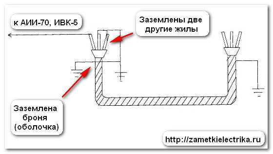
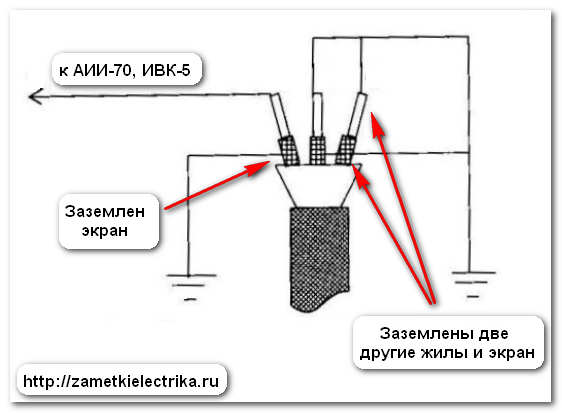
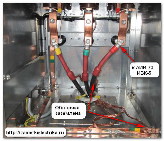
The increased rectified voltage is applied to each core of the power cable in turn. During testing, other cable cores and metal sheaths (armor, screens) must be grounded. In this case, we immediately check the insulation strength between the conductor and the ground, as well as in relation to other phases.
If the power cable is made without a metal sheath (armor, screen), then an increased rectified current voltage is applied between the core and other cores, which we first connect to each other and to the ground.
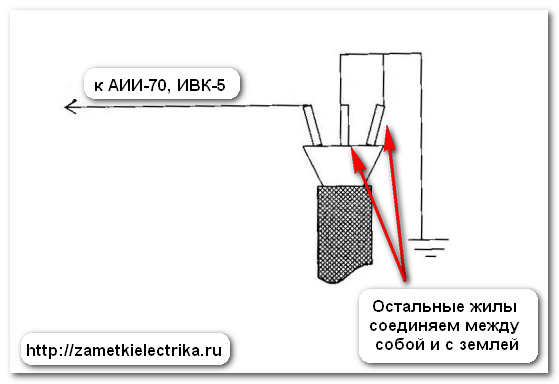
It is allowed to test all the cores of the power cable with increased voltage at once, but in this case it is necessary to measure the leakage currents for each phase.
We completely disconnect the power cable from the busbar, and separate the wires at a distance of more than 15 (cm) from each other.
We have figured out the circuit for testing rectified voltage power cables. Now we need to decide on the size and duration of the tests. To do this, open the reference books: PTEEP and PUE.
You can also use the electronic version of these books. I suggest you download the electronic version right now and completely free of charge.
I made the task a little easier for you and compiled general table taking into account PUE requirements(Chapter 1.8, clause 1.8.40) and PTEEP (Appendix 3.1., Table 10).

The duration of testing cable lines with voltage up to 10 (kV) with paper and plastic insulation after installation is 10 minutes, and during operation - 5 minutes.
The duration of testing cable lines with voltage up to 10 (kV) with rubber insulation is 5 minutes.
Now we will consider the standardized values of leakage currents and asymmetry coefficients when testing cable lines with increased rectified current voltage.
There are slight disagreements here between the PUE and PTEEP (values from PTEEP are indicated in parentheses).
If the power cable has cross-linked polyethylene insulation, for example, PvVng-LS(B)-10, then it is not recommended to test it with direct (rectified) voltage; moreover, the value of the test voltage differs significantly. I talked about this in more detail in a separate article about.
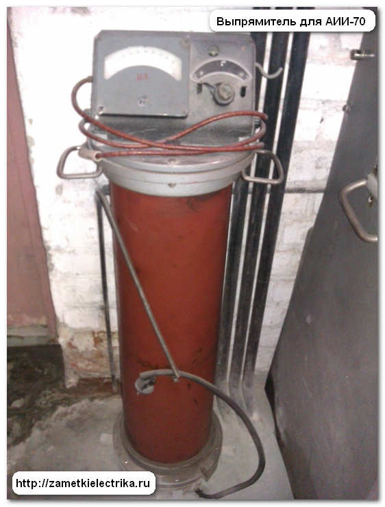
Power cable testing apparatus
Well, we have smoothly moved on to what is used to test cables with increased rectified voltage. In ours, we use either the AII-70, AID-70, or IVK-5 testing apparatus. The last two devices are used most often on the road.
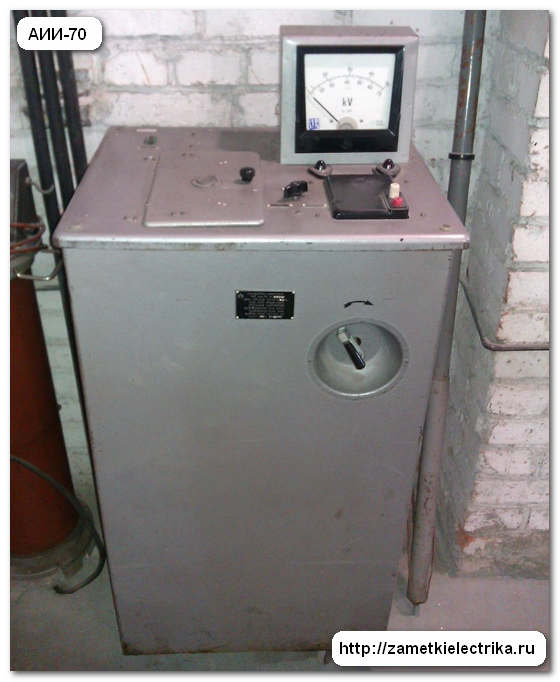
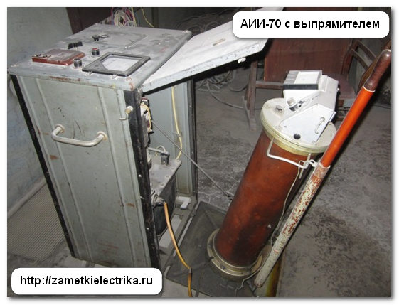

We will talk about these devices in more detail in the following articles, and if you do not want to miss the release of new articles on the site, then subscribe to receive notifications by email.
Method of testing cables with increased voltage
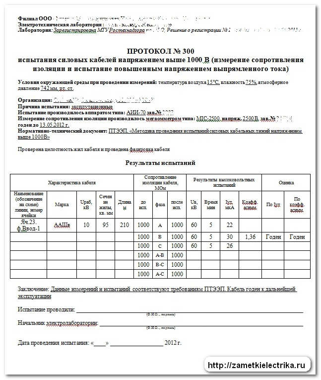
Let's say we need to conduct operational tests of a 10 (kV) power cable of the AAShv brand (3x95).
Using an AII-70 or IVK-5 apparatus, we raise the test voltage to a value of 60 (kV) at a speed of 1-2 (kV) per second. From this moment the time countdown begins. During the entire 5 minutes, we closely monitor the magnitude of the leakage current. After the time has elapsed, we record the resulting leakage current and compare it with the values in the table above. Next, we calculate the asymmetry coefficient of leakage currents by phase - it should be no more than 2, but sometimes it can be more (see table).
The asymmetry coefficient is determined by division maximum current leakage to minimum leakage current.
After high-voltage testing of the cable, it is necessary to test it again.
The cable is considered to have passed the test when:
- During the test, no breakdown, surface flashover or surface discharges occurred
- There was no increase in leakage current during the test
- the cable insulation resistance has not decreased
It happens in practice that leakage currents exceed the values indicated in the tables. In this case, the cable is put into operation, but the period of its next test is reduced.
If during testing the leakage current begins to increase, but breakdown does not occur, then the test must be carried out for more than 5 minutes. If after this the breakdown does not occur, then the cable is put into operation, but the period of its next test is reduced.
Results and protocol for high voltage cable testing
After testing the cable with increased rectified voltage, it is necessary to draw up a protocol. Below I will give you the protocol form (example) used by our electrical laboratory (click on the picture to enlarge).
P.S. This concludes the article on testing cables with increased voltage. If you have questions about the material, ask them in the comments.
All work on testing and weapons of mass destruction can be carried out by personnel authorized for these works and having the appropriate mark in the safety certificate. When carrying out this work, you may only use testing and measuring equipment that has been tested and annual certification in SII electrical networks. The use by personnel of electrical networks of installations belonging to other organizations (CP, subscribers) is prohibited.
CL 6-10-35 kV are being tested:
newly laid and after relaying - before backfilling the trench and before switching on;
those in operation - scheduled according to schedule, unscheduled - after repair or long-term shutdown (in excavation, etc.). CL up to 1 kV are tested:
newly laid and after relaying - before switching on;
unscheduled - after repairs. CL 6-10-35 kV are tested:
1 time a year - for PKL and RKL supplying especially responsible consumers;
1 time every 3 years - all other PCLs;
1 time every 5 years - all other RCLs;
Internal cable jumpers in RP and TP are tested only when newly laid and after repair.
The standards allow not to test cable lines up to 60 m long, which are outputs from distribution points and transformer substations to overhead lines.
A one-time test of several series-connected RCLs with disconnection of power transformers is allowed; beams of parallel cable lines; double or paired CLs.
The magnitude and duration of the test voltage applied to the cable conductors is given in Table. 1.
| Purpose and objects of testing |
Duration, min. |
||
|
1. Cable lines with paper | |||
|
1.1. Before turning on |
2.5 (megaohmmeter) |
||
|
1.2. In operation, scheduled according to schedule and unscheduled |
to |
2.5 (megaohmmeter after repair) |
|
|
CLs running along complex routes and supplying especially critical consumers (excluding CLs running in metro tunnels) | |||
|
CL with service life | |||
|
CL with service life | |||
|
1.3.When transferring cable lines from 6 kV to 10 kV | |||
|
with a 6 kV cable design | |||
|
1.4. Before turning on, if CL |
Code of Criminal Procedure | ||
|
1.5. Newly laid cables with a design of 10 kV connected to a 6 kV network | |||
|
2. Cable lines with plastic insulation | |||
|
newly laid | |||
|
2,5 |
|||
|
after renovation | |||
|
3. Cable jumpers in RP, TP, | |||
|
including: | |||
|
made with a single-core cable with cross-linked polyethylene insulation | |||
|
4. CLs made of single-core cable with cross-linked polyethylene insulation |
alternating voltage 0.1 Hz (ultra-low frequency-VLF) |
||
|
30 |
|||
|
5. Plastic sheaths (single-core cable hoses with XLPE insulation) |
from 10 | ||
All work on testing and weapons of mass destruction can be carried out by personnel authorized for these works and having the appropriate mark in the safety certificate. When carrying out this work, you can use only testing and measuring equipment that has been tested and annually certified by the Institute of Electrical Networks. Use by personnel of electrical networks of installations belonging to other organizations (CP, subscribers) - prohibited.
CL 6-10-35 kV are tested:
- newly laid and after relaying - before backfilling the trench and before switching on;
- those in operation - planned according to schedule, unscheduled - after repair or long-term shutdown (in excavation, etc.).
CL up to 1 kV are tested:
- newly laid and after relaying - before switching on;
- unscheduled - after repairs.
CL 6-10-35 kV are tested:
- 1 time a year - for PKL and RKL supplying especially responsible consumers;
- 1 time every 3 years - all other PCLs;
- Once every 5 years - all other RCLs;
- Internal cable jumpers in RP and TP are tested only when newly laid and after repair.
The standards allow not to test cable lines up to 60 m long, which are outputs from distribution points and transformer substations to overhead lines.
A one-time test of several series-connected RCLs with disconnection of power transformers is allowed; beams of parallel cable lines; double or paired CLs.
The magnitude and duration of the test voltage applied to the cable conductors is given in Table. 1.
Table 1
| Purpose and objects of testing | Urab, kV | Urab, kV | Duration, min. |
| 1. Cable lines with paper isolation |
|||
| 1.1. Before turning on (CLs are fully or partially made with a new cable) |
to 1 kV |
2.5 (megaohmmeter) R insulation must be at least 0.5 MOM |
|
| 6 | 36 | 10 | |
| 10 | 60 | 10 | |
| 35 | 175 | 10 | |
| 1.2. In operation, scheduled according to schedule and unscheduled | to 1 kW |
2.5 (megaohmmeter after repair) | |
| 6 | 30 | 5 | |
| 10 | 50 | 5 | |
| 35 | 175 | 5 | |
| CLs running along complex routes and supplying especially critical consumers (excluding CLs running in metro tunnels) | 6 | 20 | 5 |
| 10 | 40 | 5 | |
| CL with service life more than 15 years (except for cables in metro tunnels) |
6 | 20 | 5 |
| 10 | 40 | 5 | |
| CL with service life more than 25 years |
6 | 18 | 5 |
| 10 | 30 | 5 | |
| 1.3.When transferring cable lines from 6 kV to 10 kV with a 10 kV cable design |
10 | 50 | 5 |
| with a 6 kV cable design | 40 | 5 | |
| 1.4. Before turning on, if CL was offline for more than 5 days |
6 | Code of Criminal Procedure -0.1M |
|
| 10 | |||
| 1.5. Newly laid cables with a design of 10 kV connected to a 6 kV network | 6 | 60 | 10 |
| 2. Cable lines with plastic insulation | |||
| newly laid | to 0,66 |
3,5 | 5 |
| 2,5 (megaohmmeter) variable voltage 50 Hz |
|||
| after renovation | to 0,66 |
||
| 3. Cable jumpers in RP, TP, | |||
| including: | |||
| made with a single-core cable with cross-linked polyethylene insulation | 6 | 12 | 5 |
| 10 | 18 | 5 | |
| 20 | 25 | 10 | |
| 4. CLs made of single-core cable with cross-linked polyethylene insulation | alternating voltage 0.1 Hz (ultra-low frequency-VLF) | ||
| 6 | 12 (3Uф) |
30 20 (after repair) |
|
| 10 | 18 (3Uф) |
- | |
| 20 | 36 (3Uф) |
- | |
| 5. Plastic sheaths (single-core cable hoses with XLPE insulation) | from 10 And higher |
10 | 1 |