The DC resistance of transformer windings during operation is measured to identify faults and defects in the winding wires, in the solder joints of the windings, in the contact connections of taps and switching devices.
Such measurements can be made when putting the transformer into operation to monitor its condition after transportation or long-term storage, after repair - to control the quality of repair work, after a transformer failure (accident) to identify the nature of the damage and identify the damaged unit (element) of the transformer.
Measurements are taken on all branches.
Winding resistances of three-phase transformers, measured on identical branches different phases at the same temperature, should not differ by more than 2%. The resistance values of the windings of single-phase transformers after temperature recalculation should not differ by more than 5% from the original values.
Before measuring the resistance of the windings of transformers equipped with voltage regulation devices, at least three complete switching cycles should be performed.
According to GOST 3483-88, two methods of measuring resistance are allowed DC: Voltage drop method and bridge method for current not exceeding 20% of the rated current of the transformer winding. The voltage drop method is preferable when testing transformers of size III and larger, as well as all transformers with on-load tap-changers. The bridge method is recommended to be used when testing dry transformers and oil transformers of sizes I and II.
Resistance measurements should be made on all branches, i.e. in all positions of switching devices. If the on-load tap-changer switching device has a selector intended for reversing the regulating part of the winding or for switching coarse control stages, then measurements are made at one position of the selector. Additionally, one measurement is made at each of the other positions of the selector.
For windings of transformers that have a zero terminal, phase resistances are measured, and for windings that do not have a zero terminal, linear resistances are measured.
When measuring the resistance of one winding, the other windings of the transformer must be open-circuited.
When measuring resistance, the temperature of the transformer windings should be determined (measured).
For transformers that have not been heated and have been inoperative for at least 20 hours, the temperature of the upper layers of oil is taken as the winding temperature. In this case, measurements should be made no earlier than 30 minutes after filling transformers with a power of up to 1 MVA with oil and no earlier than 2 hours after filling transformers with a higher power.
The temperature of the windings of transformers that have been heated or have not cooled down after being disconnected from the network is determined from the results of measuring the winding resistance using the formula:
Where Θ 2 is the required temperature of the windings during testing T = 235 °C;
r Θ2 - winding resistance at temperature Θ 2, measured during testing;
r Θ1 - winding resistance at temperature Θ 1 (the value measured at the manufacturer or during commissioning tests is used);
Θ 1 - winding temperature measured during a previous test.
To compare the measured resistance with the passport resistance or another accepted as the initial (base), measured, for example, during commissioning tests or after a major overhaul with the replacement of the transformer winding, the measured resistance is brought to the temperature at which the base resistance was determined. Recalculation is carried out according to the formula:

Before making measurements, the contact connections of the terminals of the winding under test must be thoroughly cleaned of dirt, grease and traces of corrosion. It is necessary to remove the ground connections from the test subject and the free windings of the transformer.
Voltage drop measurement
The method is simple and suitable for determining resistance of any value (provided by measuring instruments required class accuracy) and gives fairly accurate measurement results.
The essence of the method is to measure the voltage drop U across a resistance r through which a direct current I of a certain magnitude is passed. Based on the results of current and voltage measurements, resistance r is determined according to Ohm's law:
When measuring small resistances (up to 10 ohms), use the circuit shown in Fig. 22, a, along which the wires of the voltmeter circuit are connected to the terminals of the transformer winding directly.
If the nameplate (initial) value of the measured resistance is 0.5% or more of the voltmeter resistance, then when measuring according to the diagram in Fig. 22, but you should take into account the current consumed by the voltmeter.
The value of the determined resistance (Ohm) is calculated by the formula:
Where U is the voltage drop across the resistance r X;
I is the current in the measuring circuit.
The resistance of the wire in the voltmeter circuit should not exceed 0.5% of the resistance of the voltmeter.
When measuring high resistance(more than 10 Ohms), and also when the resistance of the ammeter and the supply wire connecting the terminals of the ammeter and transformer is more than
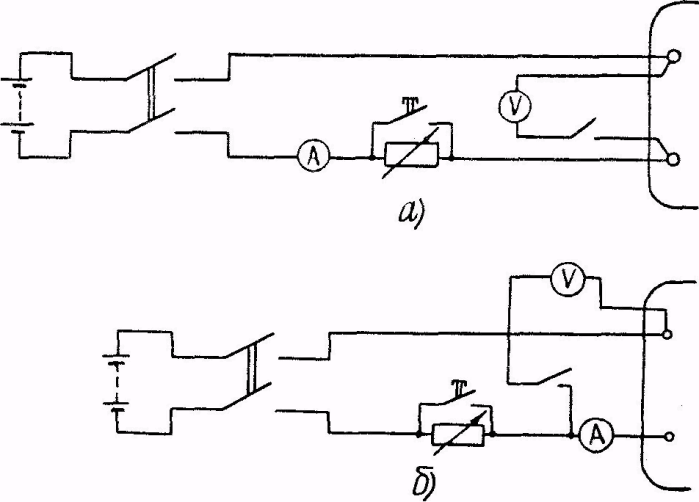
Rice. 22. Circuits for measuring DC resistance of transformer windings:
a - circuit for measuring small resistances; b - circuit for measuring high resistances
0.5% of the measured resistance, use the diagram in Fig. 22, b. According to this scheme, in addition to the resistance of the transformer winding, the resistance of the ammeter and the wire from the ammeter to the transformer are measured.
The determined resistance r X (Ohm) is calculated by the formula
Where r A and r PR are the resistances of the ammeter and wire.
In cases where measurements are made to identify a fault in one of the phases by comparing the measurement results on different phases, adjustments to the resistance of the ammeter and connecting wires are not required.
If the resistance of the transformer winding is about several tens of Ohms, and the resistance r A + r PR is about hundredths of an Ohm, the measurement error according to the scheme in Fig. 22. b is tenths of a percent and may not be taken into account.
Accuracy class measuring instruments should be no lower than 0.5, and the measurement limits of these instruments should ensure the deviation of the needle on the second half of the scale. Selecting the desired measurement limit of a voltmeter (millivoltmeter) is easy to do, knowing the passport (basic) value of the winding resistance and the selected current value in the measuring circuit (about 2-3 A or more).
Current and voltage measurements should be made at steady-state values. A current is taken to be steady-state when the ammeter needle does not change its position for 1 minute.
When testing transformers with high inductance, in order to reduce the time it takes for the current to settle in the measuring circuit, it is recommended to briefly boost the current by shunting a resistor (rheostat).
In order not to damage the voltmeter during a transient process in the measuring circuit, it should be turned on only after the current has been established, and turned off before the current is turned off.
voltammeter M2044. Accuracy class 0.2. Measurement limits: from 0.75 to 3000 mA; from 7.5 to 30 A; from 15 to 300 mV; from 0.75 to 600 V;
voltammeter M2051. Accuracy class 0.5. Measurement limits: from 0.75 to 3000 mA; from 7.5 to 30 A; from 15 to 300 mV; from 0.75 to 600 V.
Other types of magnetoelectric system devices with appropriate technical characteristics can be used.
The resistance of the slider rheostats used in the measurement circuit should be 5-10 times greater than the resistance of the transformer winding.
To bypass the rheostat, switching devices of any design for the appropriate current can be used.
To connect the measuring circuit to the terminals of the transformer winding under test, it is recommended to equip the connecting wires of the current circuit and voltage circuit with probes with pointed ends. Current circuit probes are applied to the winding terminals with inside, and the voltage circuit probes are from the outside.
Measuring direct current resistance with the RET-MOM device.
In mode 1, RET-MOM measures the active resistance of the windings of power transformers with different rated voltages and the active resistance of the windings of various relays and releases and other electrical circuits. In this mode the device has the following parameters :
Permissible active resistance of windings is up to 200 Ohms;
Permissible test current up to 12 A.
In mode 2, the device has a measurement range of 1 μOhm - 100 mOhm and allows you to measure the resistance of the following objects:
Contacts of automatic switches, breakers, releases;
Contacts of high-voltage switches;
Cable splices, bus connections;
Welded joints;
Grounding connections;
Blade contact connections and fuses;
Areas of powerful current-carrying busbars, etc.
The RET-MOM resistance measurement is based on the principle of an ammeter-voltmeter, and a 4-wire Kelvin circuit is used. According to this scheme, a constant test current is supplied to the resistance being measured using separate terminals, and the voltage drop is removed from the resistor under test using another pair of terminals.
Security measures
When carrying out measurements, it is necessary to comply with the safety requirements stipulated by the "Rules for the technical operation of consumer electrical installations" and "Safety rules for the operation of consumer electrical installations", GOST 12.2.007.0, GOST 12.1.019, GOST 22261, the safety instructions set out in this section of the manual, as well as technical documentation for the equipment in which measurements are made.
Personnel operating the device must undergo workplace safety training and, when working independently, have an electrical safety qualification group of at least III.
Attention!
Under no circumstances do not work (do not take measurements) with the device when it is open - there is a high risk of fatal injury!
If the appliance has been moved from cold air to warm room, turn it on only after it has reached room temperature and traces of condensation have disappeared. Typically this time is 1.5 - 2.5 hours.
Attention!
Arbitrary disconnection of the tested winding from the I1 terminals is not allowed!
When the device is turned on, disconnecting the winding can only begin after the indication appears on the indicator:
IT IS ALLOWED TO BREAK THE WINDING!
Under no circumstances should you break (disconnect) the winding connected to terminals I1 when the message appears on the indicator:
THERE IS CURRENT IN THE WINDING! DO NOT TEAR THE WINDING!!!
Working with the device
Preparing for work and general questions
Before starting work, it is necessary to inspect the device for obvious damage to the housing and busbars. If there is damage, work with the device prohibited!
Controls
The device modes are controlled using the buttons: ( UP), (DOWN), (FORWARD), (BACK), ENTER, START And STOP(Figure 2).
List of operating modes and their selection
When the device is turned on, the main menu is displayed:
↓ 1. Milliohmmeter mΩ →
Hello, dear readers and guests of the Electrician's Notes website.
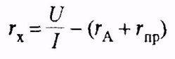
Last week we carried out acceptance tests of power oil transformers TMG11-1600/10-U1 on a complete transformer substation outdoor installation(KTPN) voltage 10/0.4 (kV).
The scope of acceptance tests presented in the article is applicable to all power oil-filled transformers with a power from 630 (kVA) to 1600 (kVA).
For oil transformers with a power of up to 630 (kVA) and more than 1600 (kVA), as well as for dry transformers, the list of tests will be slightly different, but I will tell you about this in my next articles with relevant examples.
Let me remind you that absolutely all electrical equipment (electric motors, transformers, switches, cables, etc.) newly put into operation is subjected to acceptance tests in order to monitor its technical condition.
Scope and standards of testing power transformers specified in RD 34.45-51.300-97 “Scope and standards for testing electrical equipment” (clause 6). It wouldn’t hurt to look at the manufacturer’s passport or operating manual, especially when it comes to foreign or non-standard electrical equipment. During operation, you must be guided by PTEEP (Appendix 3, clause 2), but I will tell you about operational tests of transformers next time.
First, a few words about the object.
External view of a two-transformer complete transformer substation (KTPS) with a voltage of 10/0.4 (kV).

KTPN has two TMG11 type transformers with a power of 1600 (kVA).

Explanation of TMG11-1600/10-U1:
- T - transformer
- M - oil
- G - sealed
- 11 - series and modification
- 1600 — power, kVA
- 10 - rated voltage, kV
- U1 - climatic placement and design from -45°С to +40°С
In sealed transformers, the oil is not exposed to the surrounding air, unlike transformers with expanders. Sealed transformers are filled with oil right up to the cover. By changing the volume of the corrugated walls of the tank, they withstand the thermal expansion of the oil volume.

Basic technical data of the transformer TMG11-1600/10-U1 (photo tags).

As you can see, in addition to two independent mutually redundant inputs, there is also a third power source - a diesel generator set. I haven’t looked at its power, but it looks very solid, although it works in a way that makes your ears pop—you can’t do it without earplugs.
![]()
Consumers of this KTPN, according to the PUE, can easily be classified as a special group of the first category.
Testing of transformer TMG11-1600
So, let's start in order.
I will be guided by the following normative and technical documentation:
- PUE, Chapter 1.8, clause 1.8.16 “Power transformers, autotransformers, oil reactors and grounding arc suppression reactors (arc suppression coils)”
- RD 34.45-51.300-97 “Scope and standards for testing electrical equipment” (clause 6).
- manufacturer's instructions
1. Inspection of the transformer
During the inspection, you need to pay attention to the integrity of the tank and transformer radiators, the condition of the HV and LV bushings (the absence of chips and cracks on them), the oil level in the tank and the absence of leaks, the presence and integrity of seals on the cover, filling pipe, oil level indicator and plug for oil drain.


The red float in the oil indicator should not be lower than the “A” mark - this symbolizes that the oil level is normal.
![]()
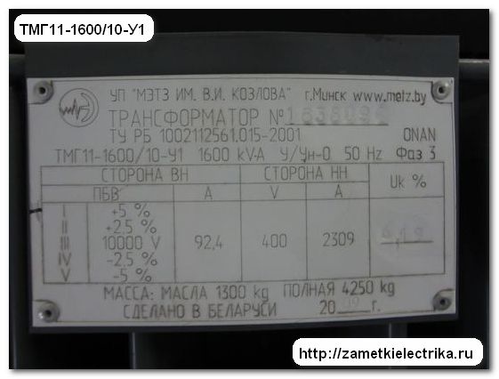
Be sure to ensure that the transformer frame is grounded.
![]()
In my example, the transformer body is grounded at .
![]()
Once, when testing a similar TMG11 transformer, only of slightly lower power, I discovered that its body was grounded, but the installers forgot to ground the neutral. If the consumer now had not a solidly grounded neutral TN, but an isolated one - IT.

2. Determination of conditions for turning on transformers without drying
The conditions for turning on transformers without drying are specified in the manufacturer's instructions. The instructions say that the newly commissioned TMG11 transformer can be turned on without drying if the insulation resistance of the HV and LV windings matches.
Thus, it turns out that the transformer can be turned on without drying if the insulation resistance of the HV and LV windings for 1 minute (R60) complies with the standards of the current regulatory and technical documents (I indicated a list of them just above in the text).
3. Measuring the insulation resistance of transformer windings
All tests must be carried out in normal conditions ambient air.
To measure the insulation resistance of the windings, you need a megohmmeter with a voltage of 2500 (V). The park has following types megaohmmeters:
- ESO202/2 voltage from 500-2500 (V)
- Ф4102/1-1М voltage from 500-2500 (V)
- MIC-2500 voltage from 50-2500 (V)
Of these, I personally prefer the M4100/5 in a carbolite “suitcase” and the MIC-2500 from Sonel.

![]()
![]()
The only disadvantage of the MIC-2500 is that at distant substations large quantities If he takes measurements at the wrong time, the battery may run out, otherwise there are only advantages. For example, the MIC-2500 can automatically discharge the line after measurement, which is very convenient in terms of electrical safety. Therefore, I always take both megohmmeters with me to distant substations for testing.
It is necessary to measure insulation resistance when the temperature of the transformer windings is not lower than 10°C. If the temperature is below 10°C, then the transformer should be heated in a warm room, with an electric oven or inductive method. The temperature of the windings can be determined by the temperature upper layers oils, i.e. You can navigate using a liquid thermometer.
In my case, the winding temperature is about 30°C.

The minimum values of insulation resistance, depending on the temperature of the windings, are given in the table. It is suitable for all oil transformers with voltage up to 35 (kV) inclusive and power up to 10 (MVA):

The TMG11 transformer under test is a two-winding transformer, so we will measure the insulation resistance according to the following scheme:
- VN - ground
- NN - earth
- VN - NN
When carrying out measurements, all untested windings and the transformer tank must be grounded.
According to the table above, at a temperature of 30°C, the insulation resistance of the windings must be at least 200 (MOhm). Here's what I got:

As you can see, the insulation resistance of the HV and LV windings of the transformer is normal (see column R60), and even with a very large margin.
In addition to the insulation resistance of the transformer windings (R60), I decided to measure its absorption coefficient (R60/R15). Based on the readings of the absorption coefficient, conclusions can be drawn about the moisture content of the transformer windings and the need for drying.
The absorption coefficient is calculated as follows. First, the insulation resistance of the winding is measured for a time of 15 seconds (R15), then the insulation resistance of the same winding is measured, only for a time of 60 seconds (R60). The value (R60) is then divided by the value (R15). This is not a mandatory measurement for our case, but I never neglect it, especially since with the help of the MIC-2500 this is done quickly and completely automatically.
The absorption coefficients (R60/R15) of the HV and LV windings of the tested TMG11 transformer are within normal limits. Let me remind you that the minimum level of this coefficient for transformers should be no lower than 1.3.
4. Measuring DC winding resistance
To carry out this measurement, our ETL has an MMR-600 microohmmeter device from Sonel, although a couple of years ago I had to reflash it to measure the resistance of windings with a much higher inductance than was originally included in the device.
Appearance of MMR-600.

Before this very for a long time We used the ITA-2 milliohmmeter, but at the last test it was rejected for several measurement limits, so now we practically don’t use it.

By the way, when measuring resistance using ITA-2, the measurement process took a very long time compared to MMR-600. Due to the high inductance of the transformer windings, ITA-2 took a long time to set the value - we had to wait for several tens of minutes, and besides, its readings “floated” somewhat.
Measurement of winding resistance to direct current must be carried out at a steady temperature of the transformer on all branches of the windings.
On the transformer cover there is a winding tap switch of type PTRL-10/125-6-96U1. This designation stands for P - switch, T - three-phase, P - type of switch (rack and pinion), L - dial drive, 10 - voltage class.
Voltage regulation occurs manually on the high side (HV) in the range from -5% to +5% of the rated voltage 10 (kV) without excitation (PBB), i.e. with the mandatory disconnection of the transformer from the network, both on the high side and on the low side.

There are 5 switching stages in total:
- I (+5%)
- II (+2.5%)
- III 10000 (V)
- IV (-2.5%)
- V (-5%)
Here is a diagram for connecting the winding branches (star circuit without zero):

The diagram shows the first position I (+5%). When switching to the second and subsequent positions, the resistance of the windings will decrease.
The switch position is fixed by a special locking device located in the drive inside the transformer tank, and a screw with a lock nut located in the drive handle.
To change the stage, you need to unscrew the lock nut of the screw on the handle and turn it up. Then you need to turn the switch handle to the required position, focusing on the indicator arrow, tighten the screw until it stops and make sure that it goes into the indicator hole, and then tighten the locknut.

For the temperature reading, in the same way as when measuring insulation resistance, we can take the temperature in upper layers oil by liquid thermometer.
The resulting resistance value should not differ by more than 2% from the obtained resistance values of adjacent phases on one branch of the windings. Also, the obtained values can be compared with the factory (passport) values, but sometimes this data is not available in the passport.
![]()
Here's what I got.
HV winding:

In the first position, the maximum difference between the resistances was 0.42%, in the second - 0.64%, in the third - 0%, in the fourth - 1.39%, in the fifth - 1.71%. As you can see, the readings obtained correspond to the norm of 2%.

LV winding:

As you can see, there is no difference in resistance on the low side (LV).
5. Transformer oil test
According to the factory instructions, the TMG11 transformer is prohibited from violating its tightness by opening the drain plugs on the tank, taps, pipes on the lid, removing insulators and the oil indicator (it’s not for nothing that seals are installed on them). In general, it is prohibited to perform any actions that could break its seals, i.e. break the seal of the tank.
In this regard, it is prohibited to take a sample of transformer oil for testing in sealed transformers.
6. Tests increased voltage
According to the PUE, it is not necessary to test the windings with increased voltage in relation to the housing and its other windings for oil-filled transformers, i.e. for our TMG11 with a power of 1600 (kVA), this test is optional. This is also confirmed by the manufacturer’s instructions, which state that it is prohibited to carry out high-voltage tests without agreement with the manufacturer.
At this point, the acceptance tests of the TMG-11 power transformer can be considered completed. If at least one measured parameter is not within the norm, then such a transformer is prohibited from being put into operation.
7. Connecting the transformer to the network
After all the tests carried out, the transformer must be switched on to the network with a push at a rated voltage of 10 (kV) for a period of at least 30 minutes. According to PTEEP (clause 1.3.7), testing is considered completed if the transformer has worked continuously and without any comments for 72 hours. Therefore, we listen and observe the operation of the transformer for 72 hours.
Then you need to check the phasing. Now I will not dwell on phasing in detail - this is the topic of a separate article with its own nuances. Let me say briefly that when phasing there must be a phase match between the two power sources. For phasing up to 500 (V), I use bipolar voltage indicators, for example, or special voltmeters with connecting wires.

For phasing on the 10 (kV) side, we use this one with an additional phasing tube (PF).

After phasing, if necessary, you can check the phase rotation. For this I have two devices:
The frequency of testing power transformers determines technical supervisor organization or enterprise, depending on the condition and results of diagnostic control (PTEEP, clause 2.1.36).
If the transformer is disconnected from gas protection or any other protection during operation internal damage, for example, from differential protection, it is allowed to be put into operation only after inspection, a series of operational tests, including oil testing, and elimination of identified faults and damage.
P.S. That's all. The article turned out to be quite voluminous and even a little longer than our methodology for testing power transformers. Thank you for your attention. If you have any questions, just ask.
1. Purpose of the work.
The purpose of commissioning works on power transformers is to check the possibility of putting transformers into operation without preliminary inspection and drying, as well as the compliance of their characteristics with the manufacturer’s data.
2. Safety precautions.
Tests and measurements of power transformers can be carried out by a team consisting of at least 2 people from ETL. The person performing high-voltage testing must have an electrical safety group of at least IV, and the rest not lower than group III. The work is carried out along with the use of protective equipment.
All transformer terminals must be short-circuited and grounded during work. Removing short circuits and grounding is allowed only for the duration of testing.
3. Technical equipment.
3.1. Means of protection:
— warning posters;
— dielectric boots or rug;
— dielectric gloves.
3.2. Devices:
— electronic megaohmmeter F 4200/2-M;
— ammeter E 526;
— DC bridge R 333;
— testing facility AID-70;
- voltmeter E 545.
— measuring kit K505
- bridge alternating current P5026
4. Determination of the transformation ratio.
By determining the transformation ratio, the correct number of turns of the transformer is checked, which must correspond to the calculated value.
Under operating conditions, determining the transformation ratio is relevant after repairing a transformer, if the windings are replaced or reconstructed. When commissioning a new transformer, the transformation ratio can be monitored if necessary.
The transformation ratio (CT) is the ratio of the voltage of the winding of a higher voltage to the voltage of the winding of a lower voltage at idling transformer.
It is known that the ratio of voltages during no-load operation of a transformer practically corresponds to the ratio of the electromotive forces of the windings and is equal to the ratio of the number of turns of the windings:
Kt = Uv/Un Ev/En = v/n (1)
During operation, it is recommended to determine the transformation ratio from the experience of no-load operation of the transformer using the method of two voltmeters while simultaneously measuring the voltage on the windings. In this case, the test is carried out by applying a voltage of 380/220 V to a higher voltage winding.
To measure the voltage on the transformer windings, voltmeters with an accuracy class of at least 0.5 must be used.
The transformation ratio should be determined on all control branches and on all phases.
For three-winding transformers (autotransformers) and transformers with a split LV winding, determining the transformation ratio of two pairs of windings is considered sufficient. As a rule, the transformation ratio between the HV-LV and MV-LV windings is determined. With this choice of pairs of windings, the transformation coefficient is determined on all control branches, since voltage regulation is carried out on one of the windings (HV or MV). In addition, some three-winding transformers have a switching device under load (OLD) on the HV winding, and a switching device without excitation (OPD) on the MV winding, and with the specified choice of winding pairs, the tests are not complicated.
Measurement schemes for determining the transformation ratio single-phase transformers and autotransformers are shown in Fig. 1-3.
For a single-phase transformer with three split LV windings, the measurement circuit is similar to the circuit given for three pairs of windings: VN-NN1, VN-NN2, VN-NN3.
To determine the transformation ratio of three-phase transformers and autotransformers with a dedicated zero of the HV winding (HV-MV), measurements are recommended to be made with single-phase excitation of the HV (MV) winding - Fig. 4-8. In this case, the voltage must be sinusoidal and symmetrical.
For transformers and autotransformers with circuits and winding connection groups Un/D-11, Un/D/D-11-11, Un auto/D-0-11, Un/Un/D-0-11 when measured according to the diagrams in Fig. 4, 6-8 the phase transformation ratio (CT.f) is determined. this is illustrated, for example, by measurement in phase A:
UA/Ua-c = A/a = Kt.f, (2)
where UA is the voltage on phase A of the HV winding;
Ua-c - voltage on phase A of the LV winding;
A,a – number of turns on the HV and LV windings of phase A, respectively.
For transformers with the circuit and connection group Un/U-0, with single-phase excitation of the high-voltage winding (see Fig. 5), half the value of the phase transformation ratio is determined.
This can be seen from the formula below for the case of excitation of phase A of the HV winding.
UA/Ua-c = A/a+c = A/2a = Kt.f/ 2, (3)
assuming that the number of turns a and c of the LV winding are equal to each other. Similar results can be obtained for the cases of excitation of phases B and C in Fig. 2, the connection of a voltmeter to the phase terminals of the LV winding is given conditionally. When powering phases A, B, C of the HV winding, any pair of windings can be selected to measure the voltage on the LV winding.
It is recommended to determine the transformation ratio of three-phase transformers that do not have a zero-output HV winding from the no-load experience with three-phase excitation of the windings.
In this case it is measured line voltage between any terminals of the high-voltage winding (the sinusoidality and symmetry of the voltage are first checked) and the linear voltages Uа-в, Uв-с, Uа-с on the LV winding are measured. Instrument readings should be taken simultaneously.
The linear coefficient is determined from the expression
Kt.l = UlVN/Ul.NN, (4)
where Kt.l – linear transformation coefficient;
UlVN – linear voltage of the HV winding;
UlNN – linear voltage of the LV winding.
For transformers with the circuit and connection group U/D-11 (Fig. 5), the transformation ratio is determined by measuring the linear voltage on the HV winding and the phase voltage on the LV winding:
U V-C /U B = U l.VN /U f.NN = Ö 3U f.VN /U f.NN = Ö 3 K t.f (5)
In cases where there is no possibility of three-phase excitation of the HV windings of a three-phase transformer (for example, in the absence of a three-phase regulating autotransformer or required quantity voltmeters or when the voltage is asymmetrical), the transformation ratio can be determined from experience with alternate supply of voltage to two phases of the HV winding
For a transformer with a circuit and connection group U/Un-0, with two-phase excitation of the HV winding and measuring the phase voltage on the LV winding (see Fig. 7), the double value of the phase transformation ratio is determined. This can be seen from the formula (6) below using the example of measuring voltage on a phase A LV windings:
U А-С /U а-0 = w A +w With/w a= 2w A /w A= 2K t.f. (6)
When determining the transformation ratio of transformers with the circuit and connection group U/D-11, the free phases of the LV winding should be short-circuited so that they do not distort the measurement results (see Fig. 6). In this case, the double value of the transformation ratio is also determined:
UА-С/Uа-с = wA + wВ/wa = 2wA/wa = 2Кт.ф. (7)
For clarity, in table. 1 shows the values of transformation ratios of three-phase transformers, determined from the diagrams in Fig. 4÷7 with single-phase and three-phase power supply to the HV (MV) winding.
In order to avoid errors when measuring the voltage of the windings, which affect the determination of the value of the transformation ratio, voltage measurements, as mentioned above, must be carried out simultaneously, which is important for possible voltage fluctuations in the 380/220 V network.
In addition, you should strive to take readings on the second half of the voltmeter scale. The selection of voltmeters with the required measurement limits can be carried out using formula (1). Knowing the passport (basic) value of the transformation ratio and specifying a convenient value for measuring the supply voltage of the HV (MV) winding U V, the value of the voltage on the LV winding U n is determined, according to which a voltmeter with the required measurement limits is selected.
Table 1
5. Determination of polarity and connection group of windings.
Checking the polarity of the windings is carried out to control the correct marking of the terminals of the windings of single-phase transformers when they are assembled into a three-phase transformer group.
Checking the connection group of the windings of three-phase transformers is carried out to establish the identity of the connection groups of transformers intended for parallel operation.
Under operating conditions, it is recommended to check the polarity and connection group of the windings using the direct current method using a galvanometer (polarometer) as a monitoring device.
To check the polarity, a direct current is briefly supplied to the HV winding of a single-phase transformer, and a galvanometer is connected to the LV winding. In this case, the pole of the direct current source and the plus of the galvanometer are connected to the winding terminals of the same name.
If the HV and LV windings of the transformer are wound in one direction, then when the DC circuit is short-circuited, the galvanometer needle deflects to the right, and when the circuit opens, to the left. This will indicate the correct marking of the ends of the windings.
The deviation of the galvanometer needle to the right is indicated by a plus sign, and to the left - by a minus sign.
To check the connection group of a three-phase two-winding transformer, a direct current source is connected in series to the terminals A-B, B-C, A-C of the HV winding and the deflection of the galvanometer needle is checked by phases a-c, v-s, a-s. in this case nine measurements are made.
When monitoring the connection groups of three-phase three-winding transformers and autotransformers, power is supplied to the HV winding, and the deflection of the galvanometer needle is monitored on the MV and LV windings. Power is then applied to the MV winding and the deflection of the galvanometer needle is monitored at the LV winding.
The arrow deflection signs for current circuit closure moments when monitoring connection groups of three-phase transformers (autotransformers) are given in Table. 2.
table 2
| Power is supplied to the HV (MV) terminals | Deviation of the arrow of the galvanometer connected to the LV (CH) terminals | ||||||
| a-b(A m -B m) | v-с(В m -С m) | a-c(A m -C m) | a-b(A m -B m) | v-с(В m -С m) | a-c(A m -C m) | ||
| Connection group 0 | Connection group 11 | ||||||
| a-b(A m -B m)b-c(B m -C m) a-c(A m -C m) |
+- | -+ | ++ | +- | 0+ | +0 | |
When carrying out experiments for the purpose of self-control, the signs of deflection of the galvanometer needle should be entered into the table and compared with the signs given in the table. 2.
A rechargeable battery or a rectifier device can be used as a power source. In this case, the voltage of the direct current source should be slightly lower than the measurement limits of the galvanometer.
Voltmeters of the magnetoelectric system, having a scale with a zero in the middle, can be used as indicator devices. The measurement limit of the device must be higher than the value of the DC voltage supplied to the transformer winding. The accuracy class of the device does not matter. From modern devices a millivoltmeter type EA2233 can be recommended with measurement limits: 75-0-75, 150-0-150 mV; 1-0-1, 1.5-0-1.5, 3-0-3, 7.5-0-7.5, 15-0-15, 30-0-30, 50-0-50, 75-0-75, 150-0-150, 250-0-250, 300-0-300, 500-0-500, 600-0-600 V.
The direct current method is simple, but requires care when making measurements, especially when checking connection group 11, when the galvanometer needle should show the zero position. Sometimes, with increased sensitivity of the galvanometer, the instrument needle does not clearly indicate the zero position. In this case, you need to reduce the voltage of the DC source. To reduce the sensitivity of the galvanometer, you can connect a resistor in series with it, the resistance of which is selected depending on the voltage of the power source and the sensitivity of the galvanometer.
6. Measuring the resistance of windings to direct current.
6 .1 General provisions
The DC resistance of transformer windings during operation is measured to identify faults and defects in the winding wires, in the solder joints of the windings, in the contact connections of taps and switching devices.
Such measurements can be made when putting the transformer into operation to monitor its condition after transportation or long-term storage, after repair - for quality control repair work, after a transformer failure (accident) to identify the nature of the damage and identify the damaged unit (element) of the transformer.
According to (1), two methods for measuring DC resistance are allowed: the voltage drop method and the bridge method with a current not exceeding 20% rated current transformer windings. The voltage drop method is preferable when testing transformers of size III and larger, as well as all transformers with on-load tap-changers. The bridge method is recommended to be used when testing dry transformers and oil transformers of sizes I and II.
Resistance measurements should be made on all branches, i.e. in all positions of switching devices. If the on-load tap-changer switching device has a selector intended for reversing the regulating part of the winding or for switching coarse control stages, then measurements are made at one position of the selector. Additionally, one measurement is made at each of the other positions of the selector.
For windings of transformers that have a zero terminal, phase resistances are measured, and for windings that do not have a zero terminal, linear resistances are measured.
When measuring the resistance of one winding, the other windings of the transformer must be open-circuited.
A rechargeable battery is used as a DC source, the capacity of which must be sufficient to stablely maintain voltage and current during measurements. A 150 Ah, 12 V battery is recommended.
When measuring resistance, the temperature of the transformer windings should be determined (measured). For transformers that have not been heated and have been inoperative for at least 20 hours, the temperature of the upper layers of oil is taken as the winding temperature. In this case, measurements should be made no earlier than 30 minutes after filling transformers with a power of up to 1 MVA and no earlier than 2 hours after filling transformers with oil. high power.
The temperature of the windings of transformers that have been heated or have not cooled down after being disconnected from the network is determined from the results of measuring the winding resistance using the formula
Q 2 = r Q 2 /r Q 1 (Q 1 + T) – T, (8)
where Q 2 is the required temperature of the windings during testing T = 235°C;
r Q 2 – winding resistance at temperature Q 2 measured during testing;
r Q 1 – winding resistance at temperature Q 1 (the value measured at the manufacturer or during commissioning tests is used);
Q 2 – winding temperature measured during a previous test.
To compare the measured resistance with the passport resistance or another, accepted as the initial (base), measured, for example, during commissioning tests or after overhaul When replacing the transformer winding, the measured resistance is brought to the temperature at which the base resistance was determined. Recalculation is carried out according to the formula:
r Q 2 = r Q 1 (Q 2 + 235 / Q 1 + 235). (9)
Before taking measurements contact connections The terminals of the tested winding must be thoroughly cleaned of dirt, grease and traces of corrosion. It is necessary to remove the ground connections from the tested and free windings of the transformer.
6.2 Voltage drop measurement
The method is simple, suitable for determining resistance of any value (provided by measuring instruments of the required accuracy class) and gives fairly accurate measurement results.
The essence of the method is to measure the voltage drop U across a resistance r through which a direct current I of a certain magnitude is passed. Based on the results of current and voltage measurements, resistance r is determined according to Ohm's law:
When measuring small resistances (up to 10 ohms), use the circuit shown in Fig. 6.1, through which the wires of the voltmeter circuit are connected to the terminals of the transformer winding directly.
If the nameplate (initial) value of the measured resistance is 0.5% or more of the voltmeter resistance, then when measuring according to the diagram in Fig. 6.1 You should take into account the current consumed by the voltmeter.
The value of the determined resistance (Ohm) is calculated by the formula:
r X= U / (I – U/ r in), (11)
where U is the voltage drop across resistance r X;
I – measuring circuit current.
The resistance of the wire in the voltmeter circuit should not exceed 0.5% of the resistance of the voltmeter.
When measuring high resistances (more than 10 Ohms), as well as when the resistance of the ammeter and the conductive wire connecting the terminals of the ammeter and the transformer is more than 0.5% of the measured resistance, use the diagram in Fig. 6.2. According to this scheme, in addition to the resistance of the transformer winding, the resistance of the ammeter and the wire from the ammeter to the transformer are measured.
Determined resistance r X(Ohm) is calculated by the formula:
r X= U * / I - (r A + r pr), (12)
where r A and r pr are the resistance of the ammeter and wire, respectively.
In cases where measurements are made to identify a fault in one of the phases by comparing the measurement results on different phases, adjustments to the resistance of the ammeter and connecting wires are not required.
If the resistance of the transformer winding is about several tens of Ohms, and the resistance r A + r pr is about hundredths of an Ohm, the error when measuring according to the diagram in Fig. 6.2 is tenths of a percent and may not be taken into account.
The accuracy class of measuring instruments must be no lower than 0.5, and the measurement limits of these instruments must ensure the deflection of the needle on the second half of the scale. Selecting the desired measurement limit of a voltmeter (millivoltmeter) is easy to do, knowing the passport (basic) value of the winding resistance and the selected current value in the measuring circuit (about 2-3 A or more) using formula (10).
Current and voltage measurements should be made at steady-state values. The current is taken to be steady-state when the ammeter needle does not change its position for 1 minute.
When testing transformers with high inductance, in order to reduce the time it takes for the current to settle in the measuring circuit, it is recommended to briefly boost the current by shunting a resistor (rheostat). In order not to damage the voltmeter during a transient process in the measuring circuit, it should be turned on only after the current has been established, and turned off before the current is turned off.
voltammeters with accuracy class 0.2 and 0.5. Measurement limits from 0.75 to 3000 mA; from 7.5 to 30 A; from 15 to 300 mV; from 0.75 to 600 V.
Other types of magnetoelectric system devices with appropriate technical characteristics can be used.
The resistance of the slider rheostats used in the measurement circuit should be 5-10 times greater than the resistance of the transformer winding.
To bypass the rheostat, switching devices of any design for the appropriate current can be used. To connect the measuring circuit to the terminals of the transformer winding under test, it is recommended to equip the connecting wires of the current circuit and voltage circuit with probes with pointed ends. Probes current circuits are applied to the winding terminals from the inside, and the voltage circuit probes are applied from the outside.
7. Measurement of current and no-load losses at low voltage.
For operating conditions, the no-load test (OC) at low voltage is the main way to measure no-load current and losses.
Measurements of losses of XX transformers during their commissioning and during operation are carried out in order to identify possible turn short circuits, short circuits in the elements of the magnetic circuit and short circuits of the magnetic circuit to the transformer tank.
It is recommended to carry out XX experiments at a low voltage of 380/220 V. In this case, the voltage is applied to the LV winding, while the other windings remain free. It is preferable to excite the windings with a linear voltage of 380 V, since the phase voltage of the network may have a significant deviation from the sinusoidal shape of the curve, which will lead to distortion of the measurement results.
Before conducting an experiment on a XX transformer in operation, it is necessary to demagnetize its magnetic circuit from residual magnetization that occurs as a result of a sudden drop in the supply voltage (disconnection of the transformer from the network) and a break in the current when it does not cross zero.
Residual magnetization is removed by passing direct current of opposite polarities through one of the windings of each core of the transformer magnetic core.
The demagnetization process is carried out in several cycles. In the first cycle, the demagnetization current must be at least twice the current of the XX transformer at the rated voltage; in each subsequent cycle, the demagnetization current must be approximately 30% less than the current of the previous cycle. In the last cycle, the demagnetization current should not be greater than the XX transformer current at a voltage of 380 V.
Portable batteries and rectifiers can be used as a source of direct current.
When commissioning a new transformer, removal of residual magnetization may not be carried out if the transformer was not heated by direct current and the measurement of current and XX losses was not preceded by measurement of the winding resistance to direct current.
During commissioning tests, the XX experiment should be carried out before starting other types of tests.
The circuit for measuring the current and losses of a three-phase three-winding transformer is shown in Fig. 7.1.
The 380 V voltage supplied to the LV winding of the transformer is monitored by a voltmeter.
It should be noted that it is possible to measure AC losses with a frequency deviation of no more than ± 3% of the nominal value (50 Hz).
For transformers in operation, AC losses are not standardized, therefore, if the frequency of the tested voltage deviates up to ± 3%, there is no need to make corrections to the measured values of AC losses by voltage frequency.
Three-phase transformers are tested by measuring phase-by-phase losses. This allows the measured loss values of each phase to be compared not only with factory data, but also with each other, which makes it possible to identify the faulty phase.
With phase-by-phase excitation of three-phase transformers, three experiments are performed (see Fig. 7.1).
First experience. Short-circuit the phase winding A, excite the phase windings V And With, measure the current and losses XX I ¢ sun, P ¢ sun.
Second experience. Short-circuit the phase winding V, excite the phase windings A And With, measure the current and losses XX I ¢ ac, P ¢ ac.
Third experience. Short-circuit the phase winding With, excite the phase windings A And V, measure the current and losses XX I ¢ av, P ¢ av.
Corrections are made to the measured values of XX losses to take into account losses in the P cx circuit. . To determine the power consumed by the circuit (devices and connecting wires), the losses P cx are measured. with the transformer disconnected from the measuring circuit.
Losses P ¢ sun, P ¢ ac, P ¢ av transformer are calculated by the formula:
P = P ¢ - P cx. (13)
In the absence of a defect in a three-phase transformer, the losses P ¢ sun and P ¢ aw with a permissible deviation of ± 5% are practically equal. Losses P ¢ ac are 20-25% (depending on the design and number of transformer magnetic cores) greater than losses P ¢ sun and P ¢ av.
The losses of XX transformers obtained from no-load experiments at low voltage do not need to be reduced to the rated voltage of the transformer. They are compared with similar losses measured at the same voltage at the manufacturer or during commissioning tests of a newly introduced transformer.
In cases where it becomes necessary to reduce the losses measured at low voltage to the rated voltage, first calculate the total losses of the transformer using the formula:
P 0 = (P ¢ sun + P ¢ ac + P ¢ aw) / 2. (14)
The P0 loss is then reduced to the rated voltage using the expression:
P 0.priv = P 0 n , (15)
where U nom is the rated voltage of the LV winding of the transformer (V);
U¢ – voltage measured in the XX experiment (V);
n – indicator equal to 1.9 for cold-rolled grain-oriented electrical steel.
Instruments used in XX experiments must be at least accuracy class 0.5.
The voltage supplied to the transformer can be regulated using autotransformers of the RNO series or other similar regulating autotransformers.
To select a wattmeter and ammeter (milliammeter) with the required measurement limits, it is recommended to be guided by previously measured values of current and AC losses at a voltage of 380 V.
In the absence of such data, the approximate expected value of the XX losses of the transformer as a whole can be determined using formula (15).
P 0 = P 0.priv n,
substituting instead of P 0.priv the passport value of losses XX at the rated voltage, instead of U ¢ - the voltage of 380 V used in the experiment XX, and instead of U nom - the rated voltage of the LV winding of the transformer (when connecting the LV winding in a triangle).
The approximate phase value of the losses ХХ can be calculated using formula (15), keeping in mind that the losses Рас are approximately 40% greater than the losses Рсс and Рав. Losses and are defined as the quotient of division 2 P 0 /3.4.
8. Methods for determining insulation parameters.
8. 1 General provisions
To assess the condition of the main insulation of transformers (reactors) in operation or when commissioning new equipment, the values of the main insulation parameters are measured: insulation resistance, dielectric loss tangent (tgd) and capacitance (C).
To make a decision on the possibility of further operation of the transformer, a comprehensive analysis of the measured values of insulation parameters is carried out, a comparison of the measured absolute values of the parameters with previously measured values is carried out, and the dynamics of changes in these parameters are also analyzed.
When commissioning new transformers or transformers after repair, the measured values of insulation parameters can be compared with their maximum permissible values if they are established by regulatory and technical documentation.
This section describes methods for measuring the main insulation parameters of transformers on equipment taken out of service.
According to measurements of insulation parameters, it is allowed to carry out at an insulation temperature of at least 10°C.
When commissioning new transformers, it is recommended to measure the insulation parameters at a temperature of not lower than 10°C for transformers with a voltage of 110-150 kV and not lower than 20°C for transformers with a voltage of 220-750 kV.
If the insulation temperature is below 10 °C, then the transformer must be heated. The insulation temperature is taken to be the temperature of the transformer windings, determined by the DC resistance. On three-phase transformers 35 kV and above, it is recommended to measure DC resistance on phase B. Temperature values are reliable if the time intervals between the end of temperature measurement and the beginning of measurement of insulation parameters are no more than:
three hours – for transformers with a capacity of 10 MVA and above;
two hours – for transformers with a power from 1 MVA to 10 MVA;
one hour – for transformers with a capacity of up to 1 MVA inclusive.
If the transformer was heated by current short circuit, no-load losses or direct current, then measurements of insulation parameters should be made no earlier than 1 hour after heating stops; if heating was carried out using the induction method - no earlier than 30 minutes.
If the transformer was not heated and was inoperative for a long time (several days), then the temperature of the upper layers of oil (for oil-filled transformers) and the ambient air temperature (for dry transformers) can be taken as the insulation temperature.
Measurements of insulation resistance, tg d and capacitance of transformer windings are carried out according to the diagrams in Table. 3.
The terminals of the winding on which measurements are made are connected to each other. For autotransformers, the output of one of the windings with autotransformer coupling may not be connected to the measurement circuit.
The sequence of measuring insulation characteristics according to the diagrams in Table. 3 is not standardized.
Table 3
Schemes for measuring insulation resistance, dielectric loss tangentand capacitance of transformer windings
| Two-winding transformers and three-winding autotransformers | |||||
| Winding on which measurements are made | Grounded parts of the transformer | Winding on which measurements are made | Grounded parts of the transformer | ||
| NNVN | VN, tankNN, tank | NNSN (HV+CH+LV) |
SN, VN, tankVN, NN, tank NN, SN, tank |
NN 1 NN 2 (VN+NN 1(2)) (VN+NN 1 +NN 2) |
NN 2, tank, VNNN 1, tank, VN NN 1, NN 2, tank NN 2(1), tank |
Note. According to measurements according to the diagrams (HV + LV) - tank; (HV+CH) – LV, tank; (HV+CH+LV) – tank; (HV+LV 1(2)) – LV 2(1), tank; (VN + LV 1 + LV 2) – the tank is produced in cases where, when measuring according to the main schemes, results are obtained that do not satisfy the permissible values established by the normative and technical documentation.
The outer surface of transformer bushings must be dry and clean. It is not recommended to take measurements in wet weather.
8 .2 Insulation resistance measurement
Before starting each measurement and when repeated measurements The transformer winding under test is grounded for at least 2 minutes to remove the absorption charge.
Schemes for measuring insulation resistance, by sections of transformer insulation
| Isolation area | Megohmmeter terminals (clamps) | |||
| Potential (r x) | Grounded (-) | Screen (E) | ||
Three-winding transformers Transformers with split LV winding |
VN-NNVN-tank NN 1(2) -NN 2(1) |
VNVN | NNBak | BakNN |
The insulation resistance values of sections of two-winding transformers can also be determined by calculation using the following formulas:
R 1 = 2R HH / (1+R HH /R HV+NN – R HH /R HH);
R 2 = R 1 R HH / (R 1 – R HH);
R 3 = R 1 R HV+LV / (R 1 – R HV+LV), (16)
where R HH, R HH, R HV+LV – winding insulation resistance, measured according to the diagrams in table. 3;
R 1 – resistance of the insulation section LV – tank;
R 2 – resistance of the LV – HV insulation section;
R 3 – resistance of the HV insulation section – tank.
8.3. Measuring dissipation tangent and capacitance
In accordance with the measurement of the dielectric loss tangent and capacitance of power transformers, it is recommended to carry out at a voltage from 25 to 60% of the test voltage of 50 Hz frequency. It is allowed to make measurements at a voltage of 10 kV. Under operating conditions, measurements on disconnected and decommissioned equipment, as well as when commissioning a new transformer or a transformer after repair, are carried out at a voltage of 10 kV.
8.3.1. Measurement schemes.
The dielectric loss tangent and the capacitance of the windings of power transformers are measured according to the diagrams in Table. 3. In this case, the sequence of measurements is not standardized.
Under operating conditions, when the tanks of the tested objects (transformers, reactors) are grounded, an inverted bridge measuring circuit is used to measure tgd and capacitance. In some cases, when the need arises and it is possible to isolate the transformer tank, a normal measurement scheme can be used. In this case, it is enough to install the transformer tank on wooden blocks. The tank insulation resistance must be several tens of times greater than the maximum resistance of the measuring branch of the AC bridge.
The normal measurement scheme is also used to determine the tgd of the insulation zones between the windings of the transformer.
When measuring tgd and the capacitance of one of the transformer windings, the other “free” windings are grounded.
In cases where the tgd of any winding is too high, it is recommended to measure the tgd of individual sections of the transformer insulation.
Measurement schemestgdand transformer capacities
| Transformers, autotransformers | Isolation area | Bridge measuring circuit | |||
| to the bridge Cx | VP P5023 | E+D+ | |||
| Double-winding transformers, autotransformers | LV-tankVN+LV-tank | InvertedInverted Inverted |
NNVN and NN | VN+BakBak | TNTN |
| Three-winding transformers | NN-tankVN-tank CH+HV- tank HV+MV+LV-tank |
InvertedInverted Inverted Inverted Inverted |
NNVN | HV+CH+BakCHN+LV+Bak HV+LV+Tank |
TNTN |
The procedure for measuring tgd and capacitance of individual sections of transformer insulation is given in table. 5
Table 5
Measurement schemestgdand capacity of individual sections of transformer insulation
| Transformers, autotransformers | Isolation area | Bridge measuring circuit | Connecting the transformer leads and tank | |||
| to the bridge Cx | VP P5023 | D+ | to the bridge E | |||
| Double-winding transformers, autotransformers | NN-bakVN-NN | InvertedNormal Inverted |
NNVN | BakNN+TN | TN— | VNBak |
| Three-winding transformers | NN-bakSN-NN | InvertedNormal Inverted Normal Inverted Normal |
NNSN | BakNN+TN | TN— | VN, SNBak, VN |
| Transformers with split LV winding | NN 1 - tankNN 1 - NN 2 | InvertedNormal Inverted Normal Inverted Normal |
NN 1 NN 1 | BakNN 2 +TN | TN— | HV, LV 2 Tank, HV |
The values of tgd and capacitance of the insulation sections of two-winding transformers can also be determined by calculation using the formulas:
tgd 1 = (C HH tgd HH - C B H tgd B H + C VN+LV tgd VN+LV) / (C HH - C B H + C VN+LV);
tgd 2 = (C HH tgd HH + C B H tgd B H - C VN+LV tgd VN+LV) / (C HH + C B H - C VN+LV);
tgd 3 = (С В H tgd В H + С ВН+НН tgd ВН+НН - С HH tgd HH) / (С ВН + С ВН+НН - С HH), (17)
C 1 = (C HH - C B H + C VN + NN) / 2;
C 2 = (C B H + C H H - C BH + NN) / 2;
C 3 = (C VN + NN + C B H - C HH) / 2, (18)
where tgd HH, tgd В H, tgd ВН+НН, С HH, С В H, С ВН+НН are the values of the dielectric loss angle and capacitance, measured according to the diagrams in Table. 3;
tgd 1, tgd 2, tgd 3, C 1, C 2, C 3 are the values of the dielectric loss angle and the capacitance of the insulation sections, respectively: LV tank, HV-LV, LV tank.
8.3.2. Testing facility equipment.
In electrical installations where there are no strong influences of electric fields, a phase regulator may not be used in the installation diagram.
Voltage transformers of types NOM-6, NOM-10 can be used as a test transformer. Voltage transformer NOM-6 is used for equipment with voltage class up to 6 kV.
To regulate the test voltage, regulating autotransformers of the types RNO-250-2, AOSN-20-220 are recommended. When choosing a regulating autotransformer, it should be assumed that the power of the voltage regulator should not be lower than the power of the test transformer.
To regulate the phase of the test voltage, phase regulators such as MAF (0.22 kVA) or FR (0.5-5 kVA) are recommended.
8.4. Processing the results of measuring insulation parameters.
To be able to compare the measured values of insulation parameters with the basic values and to make a decision on the possibility of further operation of the transformer, the measured parameter values are reduced to the winding temperature at which the basic parameter values were measured. Recalculation is carried out using the following formulas.
For insulation resistance:
R pr = R and x K 2 (19)
For tgd: tgd pr = tgd and x K 1
where R inc, tgd inc are the given values of insulation resistance and tgd inc, respectively;
R and, tgd and – respectively measured values of insulation resistance and tgd pr;
K 1 , K 2 – reduction coefficients.
The values of K 1 and K 2 are given in Table 6.
Table 6
Coefficient valuesK 1 AndK 2
Notes: 1. t 2 – highest temperature; t 1 – lowest temperature.
2. The values of the coefficients K 1 and K 2 not indicated in the table are determined by multiplying the corresponding coefficients. For example, the coefficient K 1 corresponding to a temperature difference of 12 ° C is determined by the formula K 1 = K 10 x K 2 = 1.31 x 1.06 = 1.39
9. Methods for determining the short-circuit resistance of transformer windings.
The short circuit impedance (z t) of transformers 125 MV A and above is determined in order to identify possible deformations with damage to the insulation of the windings caused by through short circuits. To do this, the measured value zt is compared with the initial - basic value of this parameter, determined on a working transformer.
In the documentation supplied by the transformer manufacturer, the arithmetic mean values z t of all three phases are given as the base values for a three-phase transformer, but using them as base values is not recommended, since if there is deformation in any winding of one of the transformer phases, it may may not be identified, because the phase value z t of this winding may be “lost” when calculating the arithmetic mean z t.
When monitoring the condition of single-phase transformers, factory data can be used as basic data.
The phase value z t of the transformer (Ohm) is determined from the expression
z t.iz. = U k.iz. / I k.iz. , (20)
where U k.iz. – measured value of phase short circuit voltage, V;
I k.iz. – measured value of the phase short circuit current, A.
The short circuit voltage and current are determined from the short circuit test, which is carried out at low voltage (380, 220 V).
When conducting a short circuit experiment during operation, the transformer is excited from the side of the higher voltage winding (HV, MV). When testing three-phase transformers, three-phase voltage is applied to the winding, and short-circuit current and voltage measurements are made sequentially on each phase.
Simultaneously with the readings of the voltmeter and ammeter, the readings of the frequency meter are taken. Schemes of measurements in short-circuit experiments of three-phase and single-phase transformers and autotransformers using an ammeter and a voltmeter are shown in Fig. 32-38 (L-6). The connection of the frequency meter in the indicated diagrams is shown conditionally. Voltage frequency monitoring can be carried out at any point in the facility’s network that is convenient for taking readings ( switchgear). The measured value of short circuit resistance (Ohm) should be converted to a frequency of 50 Hz using the formula:
z t(50) = (50 / f.from) x z t.from, (21)
Deviation of the measured phase value of short circuit resistance from base value(%) is determined from the expression:
Dz t = ((z t(50) - z t. b)/ z t. b) x 100, (22)
The condition of the windings of the transformer under test is assessed by comparing the obtained value Dz t with the maximum permissible deviation of this parameter from the basic value established by industry regulations.
Maximum sensitivity when measuring short-circuit voltage and current is achieved by selecting pairs of windings located side by side on the magnetic core.
For transformers and autotransformers equipped with on-load tap-changer switching devices, monitoring the condition of all windings is achieved by measuring the short-circuit current and voltage at the rated stage of the switching device and at the 2 extreme stages.
When testing at the maximum stage, the control winding is also tested.
When testing at the minimum stage, the control winding is eliminated, which makes it possible to identify a defective winding if, when testing at the maximum stage, a deviation of Dz t from the permissible value is detected.
When testing, it is advisable to adhere to this sequence of work to avoid frequent reconnections of short circuits. For example, when testing three-winding transformers, it is recommended to carry out measurements in the following sequence: HV-LV, MV-LV, HV-MV.
The accuracy class of measuring instruments must be at least 0.5. The use of electrodynamic devices is recommended. It is also recommended to use a set of instruments that allows measurements in four-wire networks in both single-phase and three-phase modes.
The short circuit experiment can be carried out at any value of the short circuit current, however, the selected current value should be convenient for taking readings of an ammeter and voltmeter, keeping in mind that the readings of these instruments should be taken on the second half of the scale to achieve sufficient measurement accuracy.
The selection of short circuit current and voltage values can be done as follows. The expected nominal value of the short circuit resistance (Ohm) is determined from the expression:
z t = (U nom x U k)/ (Ö 3 U nom x 100 I nom), (23)
where U nom. – linear rated voltage of the winding (HV-MV) of the transformer, kV;
U к – short-circuit voltage of the transformer, %;
I no. – rated winding current (HV-MV) of the transformer, A;
U nom. , U к – passport data of the transformer.
The rated current of the transformer (A) is determined from the expression:
I nom = S nom / Ö 3 U nom, (24)
where S nom. – rated power of the transformer, kVA
Substituting into expression (20) the values of the short-circuit current I short-circuit, convenient for reading on the ammeter scale, the expected values of the short-circuit voltage U short-circuit are determined, from which they should also be convenient for reading on the voltmeter scale.
Flexible copper or aluminum wires are used to short-circuit the terminals of transformer windings. The cross-section of the copper short circuit must be at least 30% of the cross-section of the transformer winding wire. The approximate cross-section of the transformer winding wire is determined by the value of the rated current of the winding with an average current density in the winding of about 3 A/mm 2.
The cross-section of the aluminum short-circuit must be 1.3 times larger than the cross-section of the copper short-circuit.
The connection of short circuits to the terminals of the transformer windings must be carried out using bolted connection. The connection points of the shorts must be protected to a metallic shine.
The results are recorded in the protocol.
NTD and technical literature:
- Interindustry rules on labor protection (OHS) during the operation of electrical installations.
- POT R M - 016 - 2001. - M.: 2001.
- Electrical Installation Rules Chapter 1.8 Acceptance Test Standards Seventh Edition
- Scope and standards for testing electrical equipment. Sixth edition with changes and additions - M.: NTs ENAS, 2004.
- Adjustment and testing of electrical equipment of stations and substations / ed. Musaelyan E.S. -M.: Energy, 1979.
- Collection methodological manuals on monitoring the condition of electrical equipment. Section 2 - M.: ORGRES, 1997.
| a-b, b-c | s-a | |||||
| the secondary winding is monitored by the reading of a magnetoelectric voltmeter (a voltmeter with zero in the middle of the scale). The plus of the voltmeter is connected to the terminal designated first. Based on the totality of voltmeter readings, a group of windings is judged. | In table Figure 5 shows the deflection signs of the voltmeter needle for various groups of transformer windings. Sign 0 corresponds to the absence of arrow deflection. | Table 5 | S-A | |||
| Power supplied to terminals | Deviation of the voltmeter needle connected to the terminals | a-b b-c c-a | ||||
| a-b | + | - | - | + | - | |
| b-c | - | + | - | - | + | |
| 6. After repairs associated with partial or complete replacement of windings, a group of winding connections is checked. Measurements are carried out using a direct current source (battery), connected alternately to the terminals | - | - | + | - | + |
Winding group 12 (0)
Winding group L1 A-B active power.
The obtained values of current and no-load losses do not need to be converted to the rated voltage. These parameters are compared with data from the manufacturer or acceptance tests carried out at the same voltage.
8. The transformer tank is tested for leaks hydraulic pressure column of oil high h= 0.6 m above the level of the filled conservator or by creating an excess pressure of 10 kPa in the over-oil space of the conservator. The duration of the tests is at least 3 hours. The oil temperature must not be lower than +10°C. There should be no oil leakage during testing.
9. Testing of transformer oil.
10. Testing the transformer by switching on the push to the rated voltage. During the process of 3...5-fold switching on, phenomena indicating an unsatisfactory condition of the transformer should not occur. One of the indicators of the condition of a transformer is the nature of the noise it produces. There should be no cracking inside the tank; The hum should be uniform with no periodic changes in level or tone.
11. Testing the transformer under load for 24 hours.
When voltage is applied to the insulation, polarization and conduction processes occur in it, and dielectric losses occur. These processes determine the characteristics of the insulation and its condition. To reliably assess the state of insulation (humidity, pollution, aging), the totality of its characteristics is measured, since the disadvantages of some measurements are compensated by the advantages of others.
Polarization- this is a limited displacement of bound opposite charges located in insulation, occurring under the influence electric field. Real insulating materials They have several types of polarization, but one type is predominant. In polar dielectrics, which include the insulation of transformer windings, the dipole-relaxation type of polarization predominates. This slow (inertial) type of polarization, lasting tens of seconds, is called absorption, and the current accompanying this phenomenon is the absorption current.
The change in absorption current over time when a constant voltage is applied to the insulation is shown in Fig. 7a curve 1. As the displacement of associated opposite charges is completed, this current decreases. The steady-state value of the leakage current Iut through the insulation is determined by its volumetric and surface conductivity(resistance).
Rice. 7. Change in absorption current (a) and insulation resistance (b) when a constant voltage is applied to it
The transient process of absorption current decline can be represented by an increase in insulation resistance R in time (curve 1 in Fig. 7b). The insulation resistance is measured with a megohmmeter; the resistance is read after approximately 60 seconds. This time is usually sufficient to complete the absorption process. So, one of the characteristics of insulation is the steady-state value of its resistance, denoted R60.
Obviously, the greater the resistance R60, the higher the quality of insulation.
Smallest permissible resistances The insulation of the windings of oil transformers at a temperature of 10... 30°C is:
R60=300 MOhm - for transformers with voltage up to 35 kV;
R60=600 MOhm - for transformers with a voltage of 110 kV;
R60- not standardized for transformers with a voltage of 220 kV.
Let us assume that curves 1 in Fig. 7, a and b correspond to normal dry insulation. When the insulation is moistened (contaminated, aged), its characteristics deteriorate: the leakage current increases, the insulation resistance R60 decreases (curves 2 of Fig. 7, a and b).
By measuring the insulation resistance using a megohmmeter for two points in time t 5. After repairs associated with partial or complete replacement of windings, the transformation ratios are checked. The transformation coefficients of different phases on the corresponding branches should differ from each other or from the manufacturer’s data by no more than 2%. For transformers with on-load tap-changer, this difference should not exceed the value of the regulation stage. Measurements are carried out using the method of two voltmeters with an accuracy class of at least 0.5 when a voltage of 380/220 V is applied to the higher voltage winding and the low voltage winding is open. ti and comparing resistances Rt1 5. After repairs associated with partial or complete replacement of windings, the transformation ratios are checked. The transformation coefficients of different phases on the corresponding branches should differ from each other or from the manufacturer’s data by no more than 2%. For transformers with on-load tap-changer, this difference should not exceed the value of the regulation stage. Measurements are carried out using the method of two voltmeters with an accuracy class of at least 0.5 when a voltage of 380/220 V is applied to the higher voltage winding and the low voltage winding is open. Rt2, One can judge, in particular, the moisture content of the insulation. Usually accepted t1=15 s, a t2=60 s, a relation R6o/R15 called the absorption coefficient. From curves 1 and 2 in Fig. 9.7.6 it can be seen that for wet insulation the absorption coefficient will be less than for dry insulation.
For normal insulation, the absorption coefficient, measured at a temperature of 10...30°C, must be at least 1.3.
In accordance with the nature of the dependencies shown in Fig. 7.6, real insulation can be represented by the equivalent circuit shown in Fig. 8, a.

a) b)
Rice. 8. Insulation equivalent circuit (a) and vector diagram of voltage and current (6)
Branch RaCa characterizes the inertia of the absorption phenomenon, branch R60 is the insulation resistance after the displacement of all associated opposite charges has been completed.
When applied to insulation AC voltage U flows through it full current I, consisting of absorption current Ia and leakage current Iut. This total current in accordance with the vector diagram Fig. 9.8.6 can be decomposed into active Ir and capacitive Ic components. Work UIr determines active power losses in insulation. These losses, which go towards heating the insulation, are called dielectric losses.
Attitude Ir/ Ic = tgS is called dielectric loss tangent and characterizes the resistance of the insulation to thermal breakdown, as well as the moisture content of the insulation and its general aging. The lower tgS, the higher the quality of insulation.
Largest valid values tgS, %, at a winding temperature of 10... 30 ° C for oil transformers are:
tgS =2.5% - for transformers with a voltage of 35 kV, a power of more than 10,000 kVA;
tgS =2.5% - for transformers with a voltage of 110 kV;
tgS =1.3% - for transformers with a voltage of 220 kV.
Active power losses in insulation in accordance with the designations of the vector diagram (Fig. 9.8.6) are defined as
AP = UIR=UIcoscp= Ulctgb. (9.24)
Because the real values tgS are relatively small, we can assume that /с = I- Then expression (5.24) can be written in the form
AP = UItg8. (9.25)
From the last expression it follows that
tanS = |f. (9.26)
Thus, tgS can be measured using a scheme with three measuring instruments: a wattmeter for measuring active power losses of the AP, a voltmeter for measuring the voltage applied to the insulation U and an ammeter to measure the current flowing through the insulation /. This measurement method is quite simple, but the measurement accuracy is low. More accurate measurement of tgS is performed using special high-voltage bridges.
Insulation performance measurement (
R6o, R6o/R5, tgS) is carried out for all windings of the transformer. In particular, for a two-winding transformer, measurements of insulation characteristics are carried out according to the scheme:
measurements on the LV winding - the HV winding and tank are grounded;
measurements on the HV winding - the LV winding and tank are grounded;
measurements on the LV+HV windings - the tank is grounded.
preventive tests.doc
1.4. Preventive testing of transformers during operation1.4.1. Measuring the resistance of windings to direct current.
This measurement is carried out to identify defects in the winding circuit that cause an increase in their resistance. This may occur due to poor-quality soldering or unsatisfactory condition of the tap switch contacts and connections at the points where the winding taps are connected to the inputs; break of one or more parallel wires in windings having parallel branches. On-site measurements most often reveal the unsatisfactory condition of the tap changer. Winding resistance is usually measured using the bridge method or the voltmeter and ammeter method. To measure low resistances, it is better to use a double bridge, for example bridges of the MO-61, MO-70, MOD-61 or P39, P329, etc. type, and if they are absent, use the voltage drop method, i.e. using the voltmeter and ammeter method. In the latter case, the accuracy class of the instruments must be at least 0.5. Current changes, as a rule, should not exceed 20% of the rated value in order to avoid additional heating of the winding. Sometimes, for short-term measurements (1 min.), it is allowed to take measurements at current values greater than 20% of the rated current. The measurement limits of the instruments are chosen such that readings are made in the second half of the scale.
R
is. 1.3. Circuits for measuring the resistance of transformer windings to direct current using the voltage drop method.
When measuring using the voltmeter and ammeter method, a measurement circuit is selected in accordance with the resistance being measured (Fig. 1.3.). When measuring small resistances (several Ohms), the wires of the voltmeter circuit are connected to the terminals of the transformer (Fig. 1.3, a), when measuring high resistances, a circuit is used (Fig. 1.3, b), when measuring the resistance of a winding with high inductance, it is recommended to use a circuit shown in (Fig. 1.3, c), which allows you to reduce the time to establish the current in the measuring circuit by briefly generating a current by closing the rheostat with a button. The resistance of the rheostat is taken to be no less than 8-10 times greater than the resistance of the measured winding. The resistance of the wires should not exceed 0.5% of the resistance of the voltmeter. The voltmeter is turned on when the current is steady, and it is turned off until the current circuit breaks. Care must be taken to ensure that there is no interruption or sudden change in current when the voltmeter is connected. Otherwise, the voltmeter is damaged by high voltage induced in the transformer winding by the magnetic flux of the core, which changes with the current. Sometimes, in order to somewhat reduce the influence of the inductance of the windings and thereby reduce the time of the transient mode, the windings of the transformer are turned on counter-currently so that their total magnetic flux is equal to zero or close to it. You can also reduce the transient time when measuring resistance by first applying a voltage 10-15% higher than that required to obtain the desired current, and then slowly decreasing it as you approach the desired current. After the current in the transformer winding is established, turn on the voltmeter and take readings from both instruments, which are recorded in the transformer test report. The temperature is also recorded in the protocol. environment, at which the measurement was made, the division value and the taps of the windings on which the resistance measurements were made.
A battery with a capacity of about 200 Ah at a voltage of 4-12 V is used as a current source. Rectifier units - mercury, cuprox, selenium, germanium, silicon, etc. - due to the existing small current ripple when measuring resistances with significant inductance circuits , which include the windings of transformers, wide application not found. When measuring winding resistance, you should check the correct location of the inputs on the transformer cover. Resistance measurements are carried out on all windings and all control stages. Linear resistances are measured for all available branches of the windings of all phases and for all positions of the switching device (Fig. 1.4, a). If the switching device has a range switch, then measurements are made at one position. Additionally, one resistance measurement is made at each position of the range switch. If there is a zero input in the transformer, additionally measure the phase resistance (between zero and one linear input) to check the quality of connection and soldering of the zero output (Fig. 1.4, b). If there is a zero terminal instead of measuring linear resistances

Rice. 1.4. Circuits for measuring DC resistance:
a – linear; b – phase.
It is allowed to measure phase resistance, but provided that the resistance of the zero terminal circuit does not exceed 2% of the phase resistance of the winding. If the windings of a three-phase transformer are star-connected and the zero point is not accessible, then measure the resistance ![]() on linear terminals A-B, B-C and S-A. In this case
on linear terminals A-B, B-C and S-A. In this case 
 And
And  Here
Here  And
And  - phase resistance windings A-X, B-Y and C-Z. If the linear resistances are equal to each other
  , then the resistance of the phase windings is determined as follows:
  (1.1)
(1.1)
where Rav is the average value of the measured resistance during the experiment. If the windings of the transformer are connected by a triangle, then, as in the previous case, three measurements of resistance are made at the linear terminals A-B, B-C, C-A and the arithmetic mean Rсp is determined, then:  (1.2)
(1.2)
If necessary, corrections are made to the measured winding resistance due to current consumption by the voltmeter (Fig. 1.4, a) or voltage loss in the ammeter (Fig. 1.4, b). To obtain more accurate results, measurements are usually carried out at three to four different meanings current and take the arithmetic mean of the obtained values. The obtained resistance values are recorded in the protocol, and they should not differ by more than 2% from the resistance measured on the same branch for other phases, or from the passport data (after temperature recalculation) and operational measurements. For comparison, the measured resistances lead to the same temperature. For transformers with copper windings, this reduction is performed according to the formula:
 , (1.3)
where Rx and Ro-resistance, Ohm, reduced to temperature θx, °C.
If the winding resistance Ro must be brought to its normal temperature, i.e. to 75 °C, then (1.3) can be transformed to the following form: 
 (1.4)
(1.4)
To facilitate the use of formula (3.4), the values of the coefficient k for temperatures from 0 to 75 °C are given in tables. Determination of the true temperature of the windings, when the resistances at two temperatures are known, is made using the formula:  , (1.5)
Where  And
And  - resistance of transformer windings at temperatures
  And
And  ; and - the desired and known temperatures, °C.
When measuring resistance, it is necessary to record the temperature of the winding at which the measurement is made. In this case, the temperature of the insulation of the winding of a transformer that has not been heated is taken to be: for transformers with oil, the temperature of the upper layers of oil; for transformers without oil - temperature measured with a thermometer installed in the alarm pocket on the tank lid. In this case, the pocket should be filled with transformer oil. The temperature of the winding of a transformer that is switched off for a long time in environmental conditions with a practically constant temperature is taken to be the ambient temperature. The maximum winding temperature for air-cooled transformers is 40 °C. It is advisable to measure the resistance of the HV windings in the cold state of the transformer, even in cases where information about the resistance of the windings to direct current at a certain temperature is available in factory test reports. This allows you to verify the correctness of factory and catalog data.
^ Determination of transformation ratio
The transformation ratio (K) is the ratio of the voltage of the HV winding to the voltage of the LV winding during no-load operation of the transformer:  . (1.6)
For three-winding transformers, the transformation ratio is the ratio of the voltages of the HV/MV, HV/LV and MV/LV windings.
The value of the transformation ratio allows you to check the correct number of turns of the transformer windings and is determined on all branches of the windings and for all phases. These measurements, in addition to checking the transformation ratio itself, also make it possible to check the correct installation of the voltage switch at the appropriate stages, as well as the integrity of the windings. If the transformer is mounted without opening, and there are branches that are inaccessible for measurements, then the transformation ratio is determined only for the accessible branches. When testing three-winding transformers, it is enough to check the transformation ratio for two pairs of windings, and it is recommended to carry out measurements on those windings for which the short-circuit voltage is the lowest. The passport of each transformer gives the rated voltages of both windings related to the no-load mode. Therefore, the nominal transformation ratio can be easily determined from their ratio. The measured transformation ratio at all stages of the tap changer should not differ by more than 2% from the transformation ratio at the same tap on other phases, or from the rating data, or previous measurements given. In case of a more significant deviation, the reasons for this must be clarified. If there is no suspicion of a turn short circuit, the transformer can be put into operation. In these cases, a complaint is submitted to the manufacturer. The transformation coefficient is determined:
a) the method of two voltmeters;
b) AC bridge method;
c) direct current method;
d) the method of an exemplary (standard) transformer, etc.
To determine the transformation ratio, the method of two voltmeters is recommended as the most common.

Fig. 1.5 Method of two voltmeters for determining transformation ratios:
a-for two-winding transformers; b-for three-winding transformers.
Schematic diagram to determine the transformation ratio by the method of two voltmeters for single-phase transformers is given in Fig. 1.5, a. This method consists in measuring the voltage supplied to one winding of the transformer with one voltmeter and simultaneously measuring the voltage on the other winding of the transformer with another voltmeter. When testing three-phase transformers, linear voltages corresponding to the same terminals of both tested windings are simultaneously measured. The applied voltage should not exceed the rated voltage of the transformer and should not be too low so that the measurement results are not affected by errors due to voltage loss in the windings from the no-load current and the current caused by connecting the measuring device to the secondary winding terminals.
The supplied voltage should be from one (for high-power transformers) to several tens of percent of the rated voltage (for low-power transformers), if tests are carried out to check the rating data of transformers. In most cases, voltage from a 380 V network is supplied to the transformer. If necessary, the voltmeter is connected through a voltage transformer or switched on with additional resistance. Measurements are made using measuring instruments of accuracy classes 0.2-0.5. It is allowed to connect the voltmeter V1 (Fig. 1.5) to the supply wires, and not to the transformer inputs, if this does not affect the accuracy of measurements due to the voltage drop in the supply wires. When testing three-phase transformers, a symmetrical three-phase voltage is applied to one winding and the linear voltages at the linear terminals of both windings are simultaneously measured. When measuring phase voltages, it is possible to determine the transformation ratio from the phase voltages of the corresponding phases. In this case, the transformation ratio is checked with single-phase or three-phase excitation of the transformer. If at the installation site there is data for determining the transformation ratio at the manufacturer, then when determining the transformation ratio it is advisable to measure those voltages that were measured at the manufacturer. In the absence of symmetrical three-phase voltage The transformation ratio of three-phase transformers having a D/U or U/D winding connection circuit can be determined using phase voltages with alternate phase short-circuiting. To do this, one phase of the winding (for example, phase A), connected in a triangle, is short-circuited by connecting two corresponding linear terminals of this winding. Then, with single-phase excitation, the transformation coefficient of the remaining free pair of phases is determined, which with this method should be equal to 2 Kf (for the D/U system, Fig. 1.6), when powered from the star side) or Kf/2 (for the U/D circuit, Fig. 1.7), when powered from the triangle side), where Kf is the phase transformation ratio. Measurements are made in a similar way with short-circuited phases B and C. When testing three-winding transformers, it is enough to check the transformation coefficient for two pairs of windings (see Fig. 1.5, b). If the transformer has a neutral output and all the beginnings and ends of the windings are accessible, then determining the coefficient transformations can be performed for phase voltages. The transformation ratio is checked using phase voltages with single-phase or three-phase excitation of the transformer. For transformers with on-load tap-changer, the difference in transformation ratio is not

Rice. 1.6. Determination of transformation ratios of a transformer connected according to the D/U circuit with an asymmetrical three-phase voltage:
a-first dimension; b-second dimension; c - third dimension
must exceed the values of the control stage. The transformation coefficient during acceptance tests is determined twice - the first time before installation, if the passport data is missing or raises doubts, and the second time immediately before commissioning when taking the idle speed characteristics. To speed up the measurement of the transformation ratio, a universal device of the UIKT-3 type is used, which can measure the transformation ratios of power and measuring current and voltage transformers without the use of an external source of alternating current. Simultaneously with the measurement of the transformation ratio, the polarity of the primary and secondary windings is determined. The measurement error should not exceed 0.5% of the measured value. Operating principle of the device
R 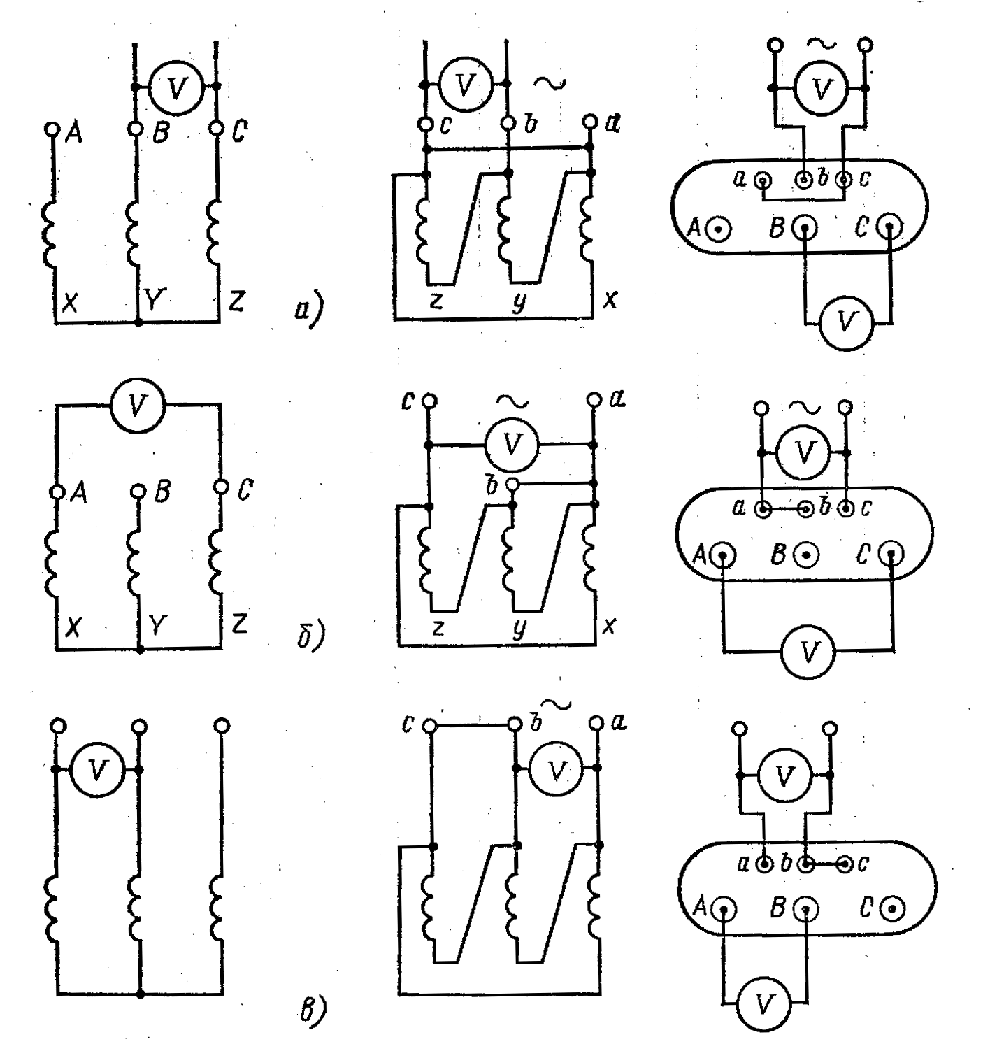
is.1.7. Determination of transformation ratios of a transformer connected according to the U/D circuit with an asymmetrical three-phase voltage:
a-first dimension; b-second dimension; into the third dimension. 
Rice. 1.8. Schematic diagram of a universal device type UIKT - 3
is based on a comparison of the voltages induced in the secondary and primary windings of the transformer with the voltage drop across known resistances (Fig. 1.8). The comparison is made using a bridge circuit.
^
1.4.3. Checking the connection group of windings of three-phase transformers and the polarity of single-phase terminals
transformers
The connection group of transformer windings is important for its parallel operation with other transformers. The condition for the permissibility of parallel operation of transformers is the identity (equality) of the winding connection groups. Failure to comply with this condition excludes parallel work, since equalizing currents will circulate between the transformers, which in some cases are many times higher than the rated ones. Groups are checked during repairs with partial or complete replacement of windings, as well as before installation if there are no passport data or there are doubts about them. The group of connections must correspond to the passport data and designations on the shield. Checking a group of winding connections is carried out using one of the following methods: direct method (phase meter); two voltmeter method; bridge method; DC method (measuring the polarity of single-phase transformers). When testing three-winding transformers, both groups of connections are checked. Simultaneously with checking the group of connections, the markings of the terminals of the transformer windings are checked. When testing, a direct method of checking a group of connections is usually used (phase meter, Fig. 1.9). Using a phase meter showing cos, the angle between the primary and secondary EMF of the transformer is determined. The phase meter does not have springs to create a counteracting moment, and therefore its needle takes an arbitrary position when the device is turned off. In phase meters with a double-sided scale, the right side shows the power factor for an inductive load, the left side for a capacitive load. When checking a connection group with a phase meter series winding A single-phase phase meter is connected through a rheostat R to the terminals of one winding, and a parallel winding is connected to the same terminals of the other winding of the transformer under test (Fig. 1.9). A voltage sufficient to normal operation phase meter (Fig. 1.10, a). To determine compound groups, the most convenient is a phase meter, which directly shows the angular displacement of electromotive forces in degrees (Fig. 1.10, b). Based on the measured angular displacement, a group of connections is determined (Fig. 1.10, c). The voltage winding of the phase meter is connected directly through a voltage transformer or additional resistance (Fig. 1.9, a). Full scheme Before switching on, the phase meter is checked under various known groups of connections and under the same conditions under which the phase meter will operate during testing.

Rice. 1.9. Schematic diagram of switching on the phase meter
When determining a group of connections of three-phase transformers, at least two measurements are made, i.e. for two pairs
clamps of the same name AB-ab and AC-ac, and in both cases the same results should be obtained. The determination of the group of connections of three-winding transformers is carried out first between the windings of high and low voltages, and then between the windings of medium and low voltages, i.e., in the same way as for two-winding transformers and using the same devices. The use of a phase meter to determine the connection groups of transformer windings is somewhat complicated by this. that in each case it is necessary to select an additional resistance to the current winding of the phase meter. Nevertheless, for mass testing of winding connection groups, the phase meter method is convenient and can be successfully used during commissioning.
The method of two voltmeters for determining the winding connection group is common and accessible; it is based on combining vector diagrams of the primary and secondary voltages and measuring the voltages between the corresponding inputs, followed by comparing these voltages with the calculated ones. 
Rice. 1.10. Definition of a group of transformer winding connections
phase meter:
A 
- circuit diagram for connecting a single-phase phase meter to determine the connection group of the transformer windings; R-active resistance included in the current circuit of the phase meter; b - general form four-square phase meter; c - phase meter with a clock scale for determining a group of compounds.
Figure 1.11, a shows a vector diagram of a transformer with a connection diagram of the V/U windings with the same winding direction of the HV and LV windings. The combination is usually made of the zero points of the HV and LV windings (Fig. 1.11.6), the zero point of one HV or LV winding with the beginnings of the HV and LV windings (A and a, B and b or C and c), as shown in Fig. 1.11 , in, where the beginnings of phases A and a are combined. Since the shift angle between the linear voltage vectors HV and LV is zero, the transformer has connection group 0. Due to the fact that not all three-phase transformers have zero terminals on the cover, it is always customary to combine the beginnings of the HV and LV windings of the same name.
Rice. 1.11. Vector diagrams for connection group U/U-12
To check the connection group of the transformer windings, connect electrically the same terminals A and a of the transformer under test, etc. A symmetrical reduced AC voltage is supplied to one winding (no matter which one),
Table 1.3.
Groups for connecting three-phase transformers using the two-voltmeter method.
| Group Connections | Angle total displacement of electromotive forces | Vector diagram of linear EMF | Ub-B (Ux-X) | Ub-C | Uc-B |
|
| 0 | 0 |  |
|
|
||
| 5 | 150 |  |
|
|
|
|
| 6 | 180 |  |
|
|
|
|
| 7 | 210 |  |
|
|||
| 9 | 270 | 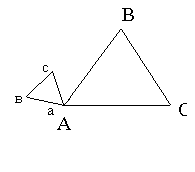 |
|
|||
| 11 | 330 |  | ||||


O 
usually no more than 250 V, and measure sequentially with a voltmeter of accuracy class 0.5 the voltage between terminals b-B, b-C and c-B when testing three-phase transformers (Fig. 1.12, a) and terminals x-X- when testing single-phase transformers (Fig. 1.12,6). Then the voltages Ub-v, Ub-c and Uc-v or Ux-x measured in volts between the terminals of the transformer are compared with the corresponding calculated voltages calculated using the formulas of Table 1.3, where Ul is the linear voltage at the terminals of the LV winding during this test; KL is the linear transformation coefficient, determined in relation to rated voltages at idle. If the measured and calculated values of the indicated voltages are respectively the same, then the connection group is correct. For single-phase transformers, only two groups of winding connections are possible
Rice. 1.12. Schemes for determining a group of connections of transformer windings using the two-voltmeter method.
(0 and 6), and checking them is much easier. Connect terminals A and a and measure the voltage between terminals X and x (Fig. 1.12, b). With connection group 0, the shift of the voltage vectors HV and LV is equal to 360 or 0, therefore, the voltage measured at terminals X and x will be Ux-x = Ul(Cl-1). With connection group 6, the shift angle of the voltage vectors HV and LV will be 180° and the voltage at terminals X and x will be Ux-x = Ul(Cl-1), where K is the calculated linear transformation ratio, determined by the ratio of the rated phase voltages of the transformer at idle progress. The connection group of single-phase transformers is conventionally designated: 1/1-0, 1/1-6.
^
M 
DC method.
Checking the connection group using the direct current method for single-phase transformers comes down to identifying unipolar terminals. The group of connections is determined according to the diagram in Fig. 1.13, but by alternately checking the polarity (plus or minus) of terminals A-X and a-x with a magnetoelectric voltmeter V having an appropriate measurement limit.
Fig.1.13. Determination of a group of connections of transformer windings using the direct current method: a-when the winding is short-circuited and the voltmeter is turned on on the HV side; b-when the winding is short-circuited and the voltmeter is turned on on the LV side; c - when the winding is open and the voltmeter is turned on on the LV side.
In this case, a DC voltage of 1-12 V from a rechargeable or galvanic battery is supplied to terminals A - X of the HV winding. An EMF of a certain sign is induced in the LV winding. The polarity of the EMF at terminals A-X is set when the current is turned on with switch P. After checking the polarity of terminals A-X, the voltmeter is disconnected without disconnecting the switch, i.e., the supply wires, and connected to terminals A-X. Polarity clamps a-x set at the moment the switch is turned on or off. If the polarity of terminals a - x when the current is turned on turns out to be the same as the polarity of terminals A - X, and when turned off it is different, then the transformer is assigned to connection group 0 (12) (Fig. 1.13, b), otherwise - to connection group 6 ( Fig. 1.13, c). To determine the group of connections of the windings of a three-phase transformer using the direct current method, to the terminals A-B windings The HV is supplied with direct current, and a direct current device (galvanometer) is alternately connected to the terminals ab, bc, ac of the lowest voltage. In the same way it is summed up
direct current to terminals BC and AC and the sign of the deviation is recorded
(, -) when turning on the device connected to terminals ab, bc, ac. A positive deviation of the device when the switch is turned on on the high voltage side is indicated by the sign “ ”, a negative deviation by the sign “-”, and the absence of deviation - by zero. All these measurements are tabulated. Each connection group has its own table. In Fig. 1.14 shows connection diagrams and corresponding tables for determining the group of connections of three-phase transformers using the direct current method.
^ Measuring the insulation resistance of power transformer windings
The insulation resistance R6o" of power transformers with parallel branches is measured between the branches, if the parallel branches can be separated into electrically unconnected circuits without unsoldering the ends. It is recommended to measure the insulation resistance before measuring the dielectric loss tangent and winding capacitance. Measuring the insulation resistance of the windings is carried out with a megger between each winding and the housing (ground) and between the windings with the remaining windings disconnected and grounded to the housing, i.e. according to Table 1.4.
Table 1.4
Measurements of insulation resistance of transformer windings.
| Windings on which measurements are made | Grounded parts of the transformer |
| Double winding transformers |
|
| NN (VN NN)* | Buck, VN |
| Three-winding transformers |
|
| NN ^ VN (VN SN)* (HV LV LV)* | Buck, CH, HV Buck, VN, NN Buck, NN, SN |
*Measurement is mandatory for transformers with a capacity of at least 16,000 kVA. When measuring, all terminals of the windings of the same voltage are connected together. The remaining windings and the transformer tank must be grounded. First, R6o" and R15" are measured, and then the remaining characteristics of the transformer. 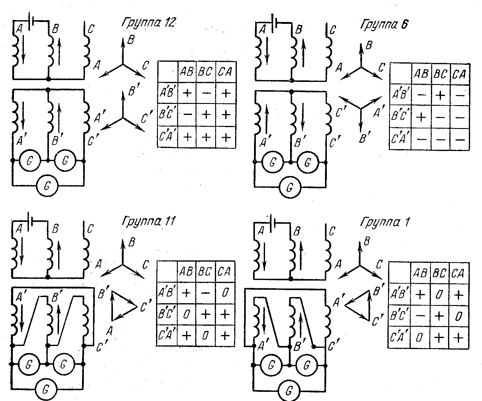
Rice. 1.14. Winding connection diagrams and tables for checking a group of connections of three-phase transformers using the direct current method
The insulation condition is characterized not only by the absolute value of the insulation resistance, which depends on the dimensions of the transformers and the materials used in it, but also by the absorption coefficient  (the ratio of the insulation resistance measured twice - 15 and 60 s after applying voltage to the test object, R6o" and R15"). It is allowed to take the beginning of rotation of the megohmmeter handle as the starting point. Measuring the insulation resistance makes it possible to judge both local defects and the degree of moisture in the insulation of the transformer windings. Insulation resistance must be measured with a megohmmeter having a voltage of at least 2500 V with an upper measurement limit of at least 10,000 MOhm. On transformers with a higher voltage of 10 kV and below, it is allowed to measure the insulation resistance with a 1000 V megohmmeter with an upper measurement limit of not less than 1000 MOhm.
P 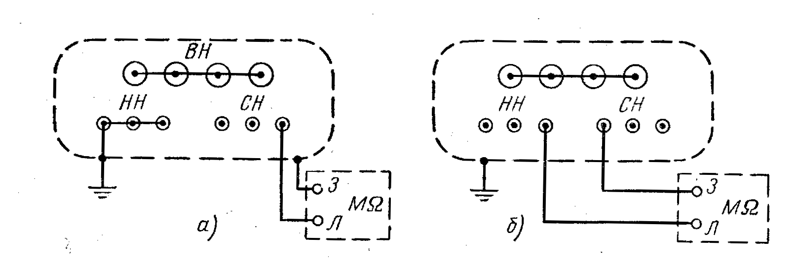
Before starting each measurement according to Fig. 1.15, the winding under test must be grounded for at least 2 minutes. Insulation resistance R6o" is not standardized, and the indicator in this case is to compare it with data from factory or previous tests. Absorption coefficient  is also not standardized, but is taken into account in a comprehensive review of measurement results. Typically, at a temperature of 10-30°C for non-humidified transformers it is within the following limits: for transformers less than 10,000 kVA with a voltage of 35 kV and below - 1.3, and for transformers 110 kV and above - 1.5-2. For transformers that are humidified or have local defects in the insulation, the absorption coefficient approaches 1. Due to the fact that during acceptance tests it is necessary to measure transformers at different temperatures insulation, it should be taken into account that the value of the coefficient changes with temperature. Dependency - shown in Fig. 1.16. To compare insulation resistance, it is necessary to measure at the same temperature and indicate in the test report the temperature at which the measurement was carried out. When comparing the results of insulation resistance measurements at different temperatures can be reduced to one temperature, taking into account that for every 10 °C decrease in temperature, R6o" increases approximately 1.5 times. The instructions in this regard give the following recommendations: the R6o" value should be reduced to the measurement temperature specified in the factory passport, it must be: for 110 kV transformers - at least 70%, for 220 kV transformers - at least 85% of the value specified in the transformer passport.
Rice. 1.15. Schemes for measuring the insulation resistance of transformer windings:
a – relative to the body; b – between the windings of the transformer

Fig.1.16. Addiction
The insulation resistance of bushings with paper-oil insulation is measured with a megohmmeter for a voltage of 1000-2500 V. In this case, the resistance of the additional insulation of the bushings relative to the connecting sleeve is measured, which must be at least 1000 MOhm at a temperature of 10-30 ° C. The main insulation resistance of the input must be at least 10,000 MOhm.