2.1. Cable lines with voltages of 6, 10,20, 35 kV are tested:
- newly laid and after relaying, before backfilling and before switching on,
- in operation: according to schedule (scheduled tests), after repair, long-term shutdown, etc. (unscheduled tests).
2.2. Cable lines with voltage up to 1 kV are tested:
- newly laid - before turning on,
- after repair, steaming, pouring, etc. (unscheduled tests).
2.3. Cable lines 6, 10, 20 and 35 kV with paper insulation, including cable inserts and outlets air lines, are tested:
a) once a year - for PKL and RKL, supplying especially responsible consumers and city life support facilities;
b) once every 3 years - for other PCLs;
c) once every 5 years for all other RCLs;
d) it is allowed not to carry out the test:
- CL which are the outputs from the RP and TP to the overhead lines,
- CLs subject to decommissioning in the next 5 years,
2.4. Cable lines 10, 20 and 35 kV with cross-linked polyethylene insulation, including cable inserts, are tested:
- after cable line repairs,
2.5. Testing of protective plastic sheaths of 10-20 kV cables with cross-linked polyethylene insulation is carried out:
- before putting the cable into operation,
- after repairs to the main cable insulation,
- in cases of excavations in the security zone of the cable line and the associated possible violation of the integrity of the shells,
- periodically - 2.5 years after commissioning, then once every 5 years.
2.6. Testing PCL using testing laboratories or portable testing facilities, are carried out from the RP. If it is impossible to carry them out from the distribution center (no access, etc.), tests can be carried out from the power center. In this case, the application must indicate the reasons for the need to carry out these works from the food center.
2.7. Simultaneous testing of several series-connected distribution cable lines with disconnection is allowed power transformers, beams of parallel CLs, double or paired CLs.
2.8. Cable outlets and inserts are tested without being disconnected from the overhead line, and at the same time, the arresters installed on the overhead line must be disconnected.
2.9. The magnitude and duration of the test voltage applied to the cable conductors is indicated in Table No. 1.
Table No. 1
|
Purpose and objects of testing |
Line operating voltage (kV) |
AC test voltage 0.1 Hz (kV) |
Duration of application test. voltage 0.1 Hz (min) |
Rectified current test voltage (kV) |
The duration of the application is rect. test voltage (min) |
|
1. Paper insulated cable lines: |
|||||
|
1.1. Before putting into operation (CLs are fully or partially made with a new cable). |
|||||
|
1.2. In operation: |
|||||
|
Scheduled and extraordinary, |
2.5 kV (megaohmmeter) |
||||
|
For cable lines supplying especially critical facilities, |
|||||
|
For cable lines with a service life of more than 15 years, except for especially responsible ones, |
|||||
|
For cable lines with a service life of more than 25 years, except for especially critical ones. |
|||||
|
1.3. Before turning on, if the CL was off for more than 5 days. |
|||||
|
2. Cable lines with plastic insulation: |
|||||
|
Newly laid |
|||||
|
After renovation |
2.5 kV (megaohmmeter) |
||||
|
3. Cable jumpers in RP and TP with paper-oil insulation |
|||||
|
4. Cable lines and cable jumpers in RP and TP made of single-core cable with cross-linked polyethylene insulation, newly laid and after repair. |
Megaohmmeter 2.5 kV |
||||
|
30 (20 after repair) |
|||||
|
30 (20 after repair) |
|||||
|
30 (20 after repair) |
|||||
|
5. Plastic sheaths (hose) of cross-linked polyethylene cables, newly laid, after repairs and periodically. |
From 10 and above |
||||
2.10. For testing cable lines DC rectified voltage is used in test installations mounted on vehicles (see clause 7.1, diagram 1) and small-sized portable installations (see clauses 7.2., 7.4.-7.10.).
2.11. Testing of cable lines with cross-linked polyethylene insulation is carried out alternating voltage above the low frequency that is generated special installations(see clauses 7.11 - 7. 14.), These installations can be made as stationary, mounted on a vehicle (clause 7.11), and as mobile, transported by any suitable by road transport(paragraph 712 -7.14).
2.12. To test the shell of cable lines with cross-linked polyethylene insulation, testing installations are used - direct current generators with a maximum output voltage of up to 5 kV (clause 7.15.) It is allowed to use high-voltage testing installations designed for testing cable lines with paper-oil insulation, subject to the following conditions :
- The output voltage should be monitored using a display with a digital readout or a kilovoltmeter scale, where 5 kV is at least a quarter of the scale.
- Leakage current monitoring should be carried out using a microammeter, manually turning off the test installation when current values exceed more than 300 μA.
2.13. When testing insulation, voltage is applied in turn to each core (phase) of the cable line, while the other two, together with the shell, are grounded.
To reduce the total test time, when testing short (up to 1 km) cable lines with cross-linked polyethylene insulation, made of single-core cables, it is possible, if the power of the installation allows, to combine all three cores and test them simultaneously. If a breakdown occurs during the test, repeat the phase test of each core to identify the damaged one.
2.14. During the testing of each phase of a paper-insulated CL, periodically and at the last minute of the test, the leakage current is measured according to the microammeter reading.
If during testing the leakage current increases or current surges appear, the test duration should be increased by 2 times. In the future, if the cable line cannot be brought to breakdown at a given test voltage, then it is tested increased voltage according to the standards for new cables - 6 times the voltage for 10 minutes each phase. If the cable line has passed this test without breakdowns, then it can be included in the work by decision of the chief engineer of the district.
When testing CLs with cross-linked polyethylene insulation, leakage current monitoring may not be carried out, however, during the test it is necessary to monitor the value of the test voltage using a kilovoltmeter. The maximum deviations of the kilovoltmeter needle during periodic changes of polarity in both directions relative to zero (see clauses 7.9.1. - 7.9.5), indicating the set value of the test voltage, should not decrease by more than 15% during the test.
If such a decrease is recorded, the test time should be increased to 1 hour. If during this time the cable line has passed this test without breakdowns, it can be put into operation.
2.15. A cable line with voltages of 6, 10, 20 and 35 kV is considered suitable for operation if it has withstood the test voltage for the time specified in clause 2.9. of this instruction (taking into account the additions under clause 2.14.). For a cable line made of 3 single-core cables with cross-linked polyethylene insulation, the test results of the protective sheath are additionally taken into account, which must withstand the DC rectified voltage test in accordance with the standards of clause 5 of Table No. 1.
2.16. After a repair test, a cable line with a voltage of up to 1 kV is considered to have passed the test if the insulation resistance, measured with a 2.5 kV megohmmeter, is not lower than 0.5 mOhm. At lower resistance values, when testing with a 2.5 kV megohmmeter does not lead to breakdown of the CL insulation, the CL should be tested using a burning installation. If during testing it is not possible to reduce the insulation resistance, the cable line, by decision of the chief engineer of the district, can be included in the work.
2.17. Testing and switching on of a 6 - 35 kV cable line after repair should be carried out within the time limits specified in clause 6 of the “Regulations on the organization and conduct of emergency restoration work at OJSC Moscow Electric Grid Company”.
2.18. When testing the sheath of single-core cables with cross-linked polyethylene insulation, the test voltage is applied between the cable shields and the ground. To do this, the screens of each of the cable line cores, in order to avoid mutual electrical contact between themselves and the grounding loop, are disconnected from the grounding loop on both sides of the line and separated in different directions. For cable line screens of 6-10 kV, if they are combined along building lengths (cable screens of 20 kV and above are not combined), it is enough to ensure that at both ends of the cable line there is only no contact with the ground loop. Working ground The test installation is connected to the grounding loop in the switchgear cell or, when working from a pit, to the grounding created from metal stakes in accordance with the provisions of clause 6.3.6. this instruction.
2.19. Leakage currents and asymmetry coefficient when testing CLs with paper insulation are recorded for additional assessment insulation, especially for end seals. The limit values of leakage current and asymmetry coefficient depending on the test voltage are given in Table No. 2.
Table No. 2
2.20. In cases where, during testing, the leakage current or asymmetry coefficient exceeds the limit values, it is necessary to inspect the end seals and insulators at both ends of the cable line, eliminate visible defects (dust, moisture, etc.), and then, if no visible defects are found, carry out retest. If, during repeated testing, increased values of leakage currents and asymmetry coefficient remain, but no leakage current surges are observed and no further increase occurs, the cable line can be put into operation by decision of the chief engineer of the district.
2.21. The protective shells of each phase of the cable line with cross-linked polyethylene insulation must withstand the test with a constant rectified voltage of negative polarity of 5 kV for 5 minutes. The leakage current should not exceed 200 μA.
2.22. Features of testing the insulation of 6-10 kV cable lines with end seals (SC) made of heat-shrinkable materials:
- If an end seal made of heat-shrinkable material is installed on the CPU on the tested CL, then tests are allowed to be carried out from the RP only when the cell on the DC is completely de-energized.
- The test voltage is raised and the leakage currents are measured when the test voltage is gradually reached. At the first stage, monitoring the test voltage values using a kilovoltmeter, gradually increasing it to a value of 5 kV, after which you should pause for 10-15 seconds during which you should measure the leakage current, first on a 10 mA scale, and then on a 1 mA scale. If the current on the 10 mA scale is higher than 1 mA and there is no tendency for it to decrease, the test should be stopped. Repeated tests will need to be carried out by the PC.
- If the leakage current on the 10 mA scale is less than 1 mA, you should switch the device to the 1 mA scale and measure the leakage current, which, with a working cable, should not exceed 500 μA. After this, the voltage increase can be continued in steps of 5 kV until the test voltage is reached. The leakage current is monitored every 5 kV, similar to the above.
- If a breakdown of the CL occurs during testing, it is necessary to disconnect the testing installation from the network, preventing the voltage from rising again, both on the damaged phase and on the remaining untested phases.
- When testing a CL with an alternating voltage of 0.1 Hz, in the absence of the ability to control leakage currents, testing should be stopped immediately at a breakdown or the first signs of an increase in load. That is, when the specified test voltage level is not established for more than 5 periods per initial stage testing or when during testing a decrease in level of more than 10% is recorded for more than 3 periods of a given test voltage oscillation frequency.
2.23. Cable lines with paper insulation that have inserts with a cross-linked polyethylene insulated cable less than 15 meters long can be tested with direct rectified voltage in accordance with the standards of Table 1. If there is an insert with a cross-linked polyethylene insulated cable of more than 15 meters, the test is carried out with alternating voltage above low frequency. In this case, the cable sheath with cross-linked polyethylene insulation is not tested
And today we will talk about testing cables with impregnated paper, plastic and rubber insulation with increased rectified current voltage.
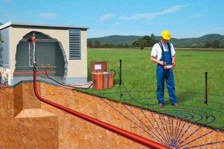
Insulation monitoring power cable voltage above 1000 (V) is carried out using the applied voltage method, which makes it possible to detect defects that may, during further operation of the cable, reduce the electrical strength of its insulation.
Preparation for high voltage cable testing
Let me immediately remind you that testing with increased voltage (high-voltage tests) is permitted to an employee over 18 years of age who has undergone special training and knowledge testing (reflected in the table for carrying out special work on his or her certificate). It looks something like this.
By the way, I specially created an online for you — you can test your knowledge.
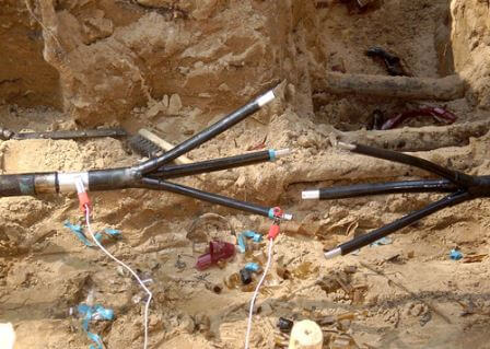
Before testing the power cable with increased voltage of rectified current, it is necessary to inspect it and wipe the funnels from dust and dirt. If during inspection any insulation defects are visible or the outer surface of the cable is heavily contaminated, then it is prohibited to proceed with testing.
It is also worth paying attention to the ambient temperature.
The ambient air temperature should only be positive, because at a negative air temperature and if there are water particles inside the cable, they will be in a frozen state (ice is a dielectric), and such a defect will not appear during a high-voltage test.
Immediately before testing the cable with increased voltage, it is necessary to measure its insulation resistance. You can read more about this in the article .
As I said above, power cable lines are tested with increased rectified current voltage.
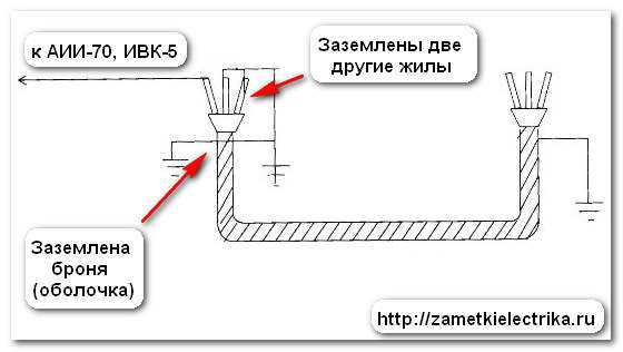
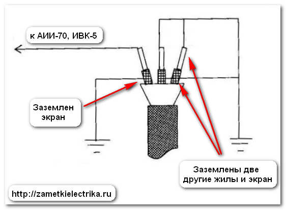
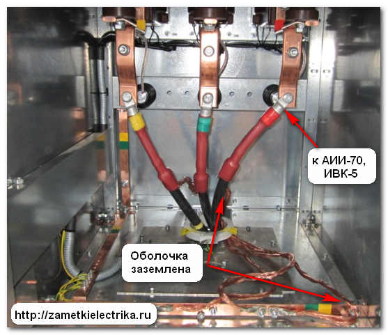
The increased rectified voltage is applied to each core of the power cable in turn. During testing, other cable cores and metal sheaths (armor, screens) must be grounded. In this case, we immediately check the insulation strength between the conductor and the ground, as well as in relation to other phases.
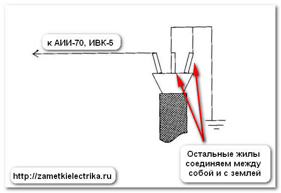
If the power cable is made without a metal sheath (armor, shield), then we apply an increased rectified current voltage between the core and other cores, which we first connect to each other and to the ground.
It is allowed to test all the cores of the power cable with increased voltage at once, but in this case it is necessary to measure the leakage currents for each phase.
We completely disconnect the power cable from the busbar, and separate the wires at a distance of more than 15 (cm) from each other.
We have figured out the circuit for testing rectified voltage power cables. Now we need to decide on the size and duration of the tests. To do this, open the reference books: PTEEP and PUE.
You can also use the electronic version of these books. I suggest you download the electronic version right now and completely free of charge.
I made the task a little easier for you and compiled general table taking into account PUE requirements(Chapter 1.8, clause 1.8.40) and PTEEP (Appendix 3.1., Table 10).

The duration of testing cable lines with voltage up to 10 (kV) with paper and plastic insulation after installation is 10 minutes, and during operation - 5 minutes.
The duration of testing cable lines with voltage up to 10 (kV) with rubber insulation is 5 minutes.
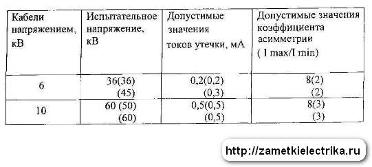
Now we will consider the standardized values of leakage currents and asymmetry coefficients when testing cable lines with increased rectified current voltage.
There are slight disagreements here between the PUE and PTEEP (values from PTEEP are indicated in parentheses).
If the power cable has cross-linked polyethylene insulation, for example, PvVng-LS(B)-10, then it is not recommended to test it with direct (rectified) voltage; moreover, the value of the test voltage differs significantly. I talked about this in more detail in a separate article about.
Power cable testing apparatus
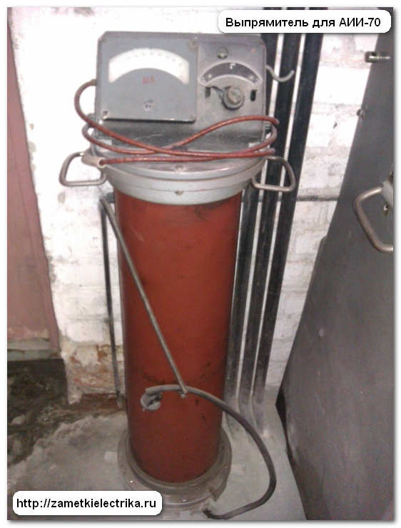
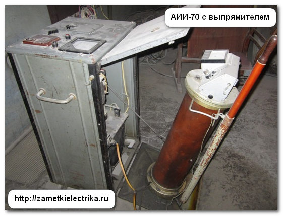
Well, we have smoothly moved on to what is used to test cables with increased voltage of rectified current. In ours, we use either the AII-70, AID-70, or IVK-5 testing apparatus. The last two devices are used most often on the road.
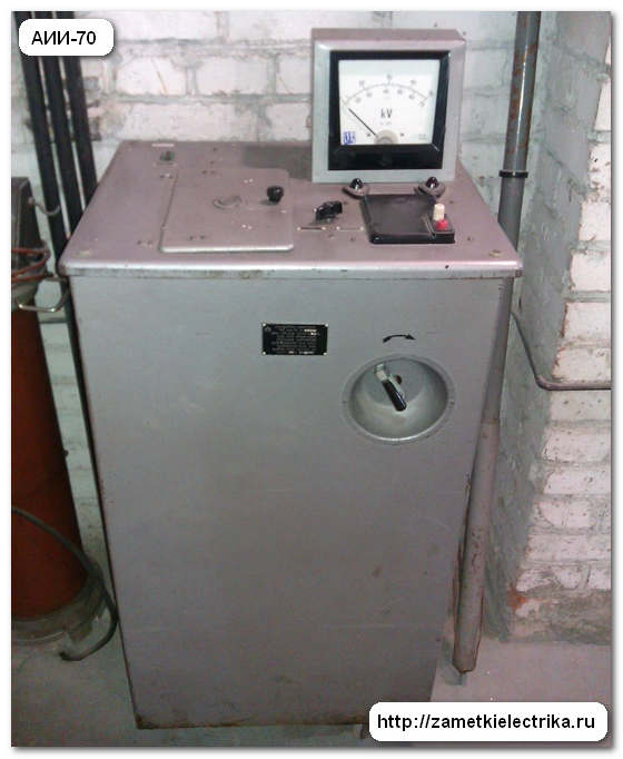

We will talk about these devices in more detail in the following articles, and if you do not want to miss the release of new articles on the site, then subscribe to receive notifications by email.
Method of testing cables with increased voltage
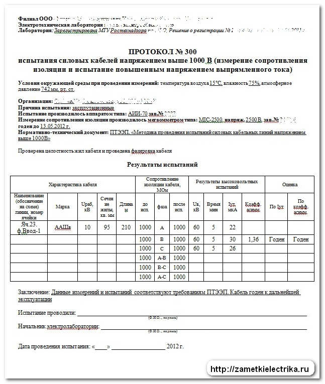
Let's say we need to conduct operational tests of a 10 (kV) power cable of the AAShv brand (3x95).
Using an AII-70 or IVK-5 apparatus, we raise the test voltage to a value of 60 (kV) at a speed of 1-2 (kV) per second. From this moment the time countdown begins. During the entire 5 minutes, we closely monitor the magnitude of the leakage current. After the time has elapsed, we record the resulting leakage current and compare it with the values in the table above. Next, we calculate the asymmetry coefficient of leakage currents by phase - it should be no more than 2, but sometimes it can be more (see table).
The asymmetry coefficient is determined by division maximum current leakage to minimum leakage current.
After high-voltage testing of the cable, it is necessary to test it again.
The cable is considered to have passed the test when:
- During the test, no breakdown, surface flashover or surface discharges occurred
- There was no increase in leakage current during the test
- the cable insulation resistance has not decreased
It happens in practice that leakage currents exceed the values indicated in the tables. In this case, the cable is put into operation, but the period of its next test is reduced.
If during testing the leakage current begins to increase, but breakdown does not occur, then the test must be carried out for more than 5 minutes. If after this the breakdown does not occur, then the cable is put into operation, but the period of its next test is reduced.
Results and protocol for high voltage cable testing
After testing the cable with increased rectified voltage, it is necessary to draw up a protocol. Below I will give you the protocol form (example) used by our electrical laboratory (click on the picture to enlarge).
P.S. This concludes the article on testing cables with increased voltage. If you have questions about the material, ask them in the comments.
Influenced various factors external environment: soil shift and its weight, temperature fluctuations and other influences on which the insulation characteristics in one way or another depend. Over time, the insulation deteriorates. For this reason, it is important to test the 10 kV cable with increased voltage. Thanks to this procedure, it will be possible to determine its condition and replace it in a timely manner. The result is trouble-free operation of the cable line, the absence of accidents and other unpleasant situations, the solution of which requires large expenses. But what voltage is the 10 kV cable tested at?
10 kV cable with cross-linked polyethylene insulation: how and with what is it checked?
Testing a cable with cross-linked polyethylene insulation for a voltage of 6/10 kV is performed with an alternating voltage with a frequency of 0.1 Hz for 30 minutes (after repair - 20 minutes). 30 kV - test voltage of 10 kV cable, 18 kV - 6 kV cable. Special VLF equipment is used, created foreign manufacturers(High Voltage Diagnostic, Switzerland; High Voltage, USA; Seba, Germany, etc.).
The test procedure for 10 kV cable is as follows:
1. All elements of the cable line, tunnels and channels in which it is located are inspected. If the end couplings have flaws, the inspection continues only after they have been eliminated. The cable shields are grounded.
2. The test voltage is applied to the cable (the time is controlled using a timer), and it slowly rises to the required value (the voltage value is determined using a kilovoltmeter on VLF equipment).
3. The magnitude of the voltage and its change in polarity is demonstrated by a kilovoltmeter. It is not uncommon for one polarity value to differ from another by five to ten percent.
4. Upon completion of the set time, the voltage is slowly reduced to zero using a special handle.
 Testing of 10 kV cable can be carried out by AC rated voltage for 24 hours, applied between the metal screen and the conductor. You need to do this:
All elements of the line should be inspected, and if the end couplings have flaws, they must be eliminated.
. When checking the cable insulation, voltage is applied to each core and the screen is grounded.
. Carefully raise the voltage to the maximum value and maintain it constant throughout the entire time. The time must be calculated starting from the moment the limit value is established.
Checking the cable sheath when laying it in the ground is carried out once every 5 years (if the cable does not have electrical breakdowns during operation). When carrying out excavation work or observing soil sediments, landslides, and erosions, an extraordinary test is performed. Upon completion of the work, an additional inspection is also carried out. To check the cable in this case, use D.C. and kenotron installation type KII-70. Voltage from of this device applied to each core in turn, the metal sheath is grounded.
For a 6 kV cable, the leakage current should not be more than 200 μA, for 10 kV - up to 500 μA.
6/10 kV cable with impregnated paper insulation: how and with what is it checked?
 Testing of this type of cable is carried out with increased voltage of rectified current. 60 kV is the test voltage value for a 10 kV cable, 36 kV for a 6 kV cable. In both cases, the check lasts 10 minutes. A special device of the AID-70M type is used. You need to proceed in the same sequence as with the previous cable.
Testing of a 10 kV high-voltage cable with increased voltage is carried out in accordance with GOST. The magnitude of the applied voltage is indicated in GOST or in the technical specifications for certain cables.
The following standards for testing 10 kV cable have been established:
In the case of re-laying and recent laying - before switching on and before the trench is backfilled;
. in operation - during a prolonged shutdown, after repairs have been carried out (not according to plan or schedule).
 Checks are carried out at the following intervals:
Once every 5 years - spare cable lines.
. Once every 3 years - main cable lines.
. Once every 12 months - spare and main lines that feed especially important users.
Now you know how to test a 10 kV cable, so this process will not cause you any difficulties. The main thing is to stick to current standards and follow safety precautions.
All work on testing and weapons of mass destruction can be carried out by personnel authorized for these works and having the appropriate mark in the safety certificate. When carrying out this work, you may only use testing and measuring equipment that has been tested and annual certification in SII electrical networks. The use by personnel of electrical networks of installations belonging to other organizations (CP, subscribers) is prohibited.
CL 6-10-35 kV are being tested:
newly laid and after relaying - before backfilling the trench and before switching on;
those in operation - planned according to schedule, unscheduled - after repair or long-term shutdown (in excavation, etc.). CL up to 1 kV are tested:
newly laid and after relaying - before switching on;
unscheduled - after repairs. CL 6-10-35 kV are tested:
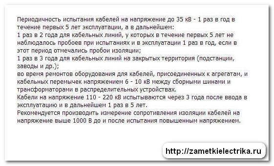
1 time a year - for PKL and RKL supplying especially responsible consumers;
1 time every 3 years - all other PCLs;
1 time every 5 years - all other RCLs;
Internal cable jumpers in RP and TP are tested only when newly laid and after repair.
The standards allow not to test cable lines up to 60 m long, which are outputs from distribution points and transformer substations to overhead lines.
A one-time test of several series-connected RCLs with disconnection of power transformers is allowed; beams of parallel cable lines; double or paired CLs.
The magnitude and duration of the test voltage applied to the cable conductors is given in Table. 1.
| Purpose and objects of testing |
Duration, min. |
||
|
1. Cable lines with paper | |||
|
1.1. Before turning on |
2.5 (megaohmmeter) |
||
|
1.2. In operation, scheduled according to schedule and unscheduled |
to |
2.5 (megaohmmeter after repair) |
|
|
CLs running along complex routes and supplying especially critical consumers (excluding CLs running in metro tunnels) | |||
|
CL with service life | |||
|
CL with service life | |||
|
1.3.When transferring cable lines from 6 kV to 10 kV | |||
|
with a 6 kV cable design | |||
|
1.4. Before turning on, if CL |
Code of Criminal Procedure | ||
|
1.5. Newly laid cables with a design of 10 kV connected to a 6 kV network | |||
|
2. Cable lines with plastic insulation | |||
|
newly laid | |||
|
2,5 |
|||
|
after renovation | |||
|
3. Cable jumpers in RP, TP, | |||
|
including: | |||
|
made with a single-core cable with cross-linked polyethylene insulation | |||
|
4. CLs made of single-core cable with cross-linked polyethylene insulation |
alternating voltage 0.1 Hz (ultra-low frequency-VLF) |
||
|
30 |
|||
|
5. Plastic sheaths (single-core cable hoses with XLPE insulation) |
from 10 | ||