I came across a diagram of a two-channel charger on the Internet. I didn’t make it for two channels at once, since there was no need - I assembled one. The circuit is fully functional and charges perfectly.
Charging circuit for car batteries
Charger Specifications
- Mains voltage 220 V.
- Output voltage 2 x 16 V.
- Charge current 1 - 10 A.
- Discharge current 0.1 - 1 A.
- The form of the charge current is a half-wave rectifier.
- Battery capacity 10 - 100 A/h.
- The voltage of the batteries being charged is 3.6 - 12 V.
Description of operation: this is a charge-discharge device with two channels with separate adjustment of the charge current and discharge current, which is very convenient and allows you to choose optimal modes restoration of battery plates based on their technical condition. The use of a cyclic reduction mode leads to a significant reduction in the yield of hydrogen sulfide and oxygen gases due to their complete use in chemical reaction, recovers quickly internal resistance and the container is in working condition, there is no overheating of the housing or warping of the plates.
The discharge current when charging with an asymmetric current should be no more than 1/5 of the charging current. Manufacturers' instructions require discharging the battery before charging, that is, forming the plates before charging. There is no need to look for a suitable discharge load; it is enough to perform the appropriate switching in the device. It is advisable to carry out control discharge with a current of 0.05 C from the battery capacity for 20 hours. The circuit allows the plates of two batteries to be formed simultaneously with separate installation of the discharge and charging current.
The current regulators represent key regulators on powerful field-effect transistors VT1, VT2.
In chains feedback optocouplers necessary to protect transistors from overload are installed. At high charge currents, the influence of capacitors C3, C4 is minimal and an almost half-wave current lasting 5 ms with a pause of 5 ms accelerates the recovery of battery plates, due to a pause in the recovery cycle, overheating of the plates and electrolysis does not occur, the recombination of electrolyte ions is improved with full use in chemical reactions of hydrogen and oxygen atoms.
Capacitors C2, C3, operating in voltage multiplication mode, when switching diodes VD1, VD2, create an additional impulse to melt coarse-crystalline sulfation and convert lead oxide into amorphous lead. The current regulators of both channels R2, R5 are powered by parametric voltage stabilizers on zener diodes VD3, VD4. Resistors R7, R8 in the gate circuits of field-effect transistors VT1, VT2 limit the gate current to a safe value.
Optocoupler transistors U1, U2 are designed to shunt the gate voltage of field-effect transistors when overloaded with charging or discharging currents. The control voltage is removed from resistors R13, R14 in the drain circuits, through trimming resistors R11, R12 and through limiting resistors R9, R10 to the optocoupler LEDs. At increased voltage on resistors R13, R14, the optocoupler transistors open and reduce the control voltage at the gates of the field-effect transistors, the currents in the drain-source circuit decrease.
Discuss the article SIMPLE ADJUSTABLE CAR CHARGER
To assemble even the simplest voltage stabilizer for a charger, you need to have at least a little knowledge of physics. Otherwise it will be difficult to understand the dependence physical quantities, for example, how as the battery charges, the resistance of the battery increases, the charging current drops and the voltage rises.
A simple current stabilizer charger made from scrap materials
There are a huge number of ready-made circuits and designs that allow you to charge a car battery. This article is on the topic of converting a computer power supply to automatic charger car battery. It tells how to assemble an automatic current stabilizer with the ability to adjust the output current.
The stabilizer circuit used in our assembled charger is quite simple and is based on an open-loop operational amplifier (OP-amp) with a high gain.
The LM358 microcircuit is used as such an operational amplifier, or it would be more correct to call it a comparator. The image shows that it has:
- two inputs (inverting and non-inverting);
- one exit.
The job of the LM358 is to balance the output by increasing or decreasing the voltage at the inputs.
A charger or simple stabilizer is a device that:
- smoothes out network ripples;
- maintains a straight line of the current graph at the same level.
How is this done? In our case, a reference voltage is supplied to one input, set using a zener diode. The second input is connected after the shunt, intended to act as a current sensor. When a discharged battery is connected to the output, the current in the circuit increases and, accordingly, a voltage drop occurs across the low-resistance resistor. On the LM358 chip, a voltage difference appears between the two inputs. The device seeks to balance this difference, thereby increasing the output parameters.
Looking at the diagram, we see that a field-effect transistor is connected to the output, which controls the load. As the battery charges, the voltage at the terminals of the device begins to increase, therefore, it begins to increase at one of the inputs of the op-amp. A voltage difference arises between the inputs, which the op-amp tries to equalize by reducing the output voltage, thereby reducing the current in the main circuit.
As a result, the battery is charged to the required voltage, that is, the set value at the charger terminals. The voltage drop across resistor R3 becomes minimal or will not exist at all. When the voltage at the inputs is equalized, the transistor closes, thereby disconnecting the load from the charger.
A feature of this circuit is that it allows you to limit the charge current. This is done using a variable resistor, which is connected in series to the divider. And by actually turning the knob of this resistor, you can change the parameters at one of the inputs. The resulting difference is again equalized by increasing or decreasing the parameters.
There are no universal schemes. Someone is interested in the issue of increasing the load current. For example, what needs to be changed in the circuit for 15 A? It will be necessary to install a variable not 5, but 10 kOhm. By also making a preliminary calculation and replacing the corresponding elements, you can easily customize the circuit to suit your needs.
Assembling the device
Of course, it’s interesting to look at the finished homemade product, then let’s start assembling the device. There are many compact boards for this design in online stores. The cost of parts for assembling this voltage stabilizer will cost less than two hundred rubles. If you buy a ready-made voltage stabilizer, you will have to pay several times more.
We will not describe all standard assembly actions; we will only note the main points. The transistor must be placed on a heat sink. Why? Because the circuit is linear and at high currents the transistor will get very hot. What is the radiator made of? It can be made from a regular aluminum corner and attached directly to the power supply fan. And, despite the fact that the radiator is quite small in size, thanks to the intense airflow it will cope with its task perfectly.
A transistor is screwed to the radiator through thermal paste; in this circuit it uses a field-effect, N-channel IRFZ44 with a maximum current of 49 A. Since the radiator is isolated from the main board and case, the transistor is screwed directly without insulating spacers.
The stabilizer board is fixed to the same aluminum corner through a brass stand. To regulate the output current, a 5 kOhm variable resistor is used. The wires are secured with plastic ties to prevent them from dangling.
As a result, you should get the following connection diagram for this stabilizer for the charger.
The power supply can be absolutely anything, either a computer power supply or a regular transformer. The cord used to connect to the outlet is a regular computer one.
Everything is ready. You can now use such an adjustable voltage stabilizer for the charger. It should be noted that the circuit is simple and inexpensive: it also functions as a charger.
This article is an answer to a question from one of the site visitors. The diagram of the battery charger is shown in Figure 1.
In general, the scheme is one of standard schemes switching on three-pin, adjustable integral stabilizer positive voltage LM317, Russian equivalent - KR142EN12A.
The scheme works as follows. With a small current flowing through the load resistance, the circuit behaves like a conventional voltage stabilizer, the output voltage of which is set by resistor R3. The resistance of this resistor can be calculated using the given formulas. When the load resistance decreases, i.e. As the current flowing through the microcircuit increases, the voltage drop across resistor R1 increases. When the voltage across this resistor approaches the opening voltage of transistor VT2, which is approximately 0.6 V, part of the load current will begin to flow through the latter. This means that after a certain amount of load current, the entire main current will be taken over by a powerful transistor. Maximum current The stabilizer in this case will be limited by the maximum collector current of the applied transistor. But the circuit has a current limiting system consisting of transistor VT1 and resistor R2. In this case, resistor R2 is a current sensor and the level of its limitation will depend on its value. The current limiting circuit works as follows. Let's say that for some reason the current flowing through transistor VT2 has increased, and the voltage drop across resistor R2, the current sensor, has also increased. When this voltage again reaches approximately 0.6 V, transistor VT1 will begin to open and shunt the base-emitter junction of transistor VT2, thereby reducing its collector current. The current limiting mode begins. With a resistance of resistor R2 of 0.1 Ohm and taking into account that a voltage of approximately 0.6 V is required to open silicon transistors, we find that the current limitation will occur at approximately 6 A. I = U/R = 0.6/0.1 = 6.
The disadvantage of this circuit is the impossibility of smoothly adjusting the output stable current, but if this charger is used to charge batteries of the same type, then this can be neglected. The choice of diodes depends, of course, on the load current. If the charger will be used for car batteries, then the TS-180 can be used as a network transformer. Read how to rewind it
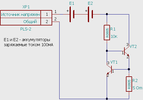
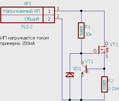
There are times when you need to pass a stable current through LEDs, limit the charging current of batteries, or test a power source, but you don’t have a rheostat at hand. In this, and not only, case, special circuit solutions that limit, regulate and stabilize the current will help. The following describes in detail the circuits of stabilizers and current regulators.
Current sources, unlike voltage sources, stabilize the output current by varying the output voltage so that the current through the load always remains the same.
Thus, a current source is different from a voltage source, just as water is different from land. Typical applications of current sources are powering LEDs, charging batteries, etc.
Attention! Do not confuse a current stabilizer with a voltage stabilizer! This could end badly =)
Simple current stabilizer on Krenka
For this current stabilizer, it is enough to use KR142EN12 or LM317. These are adjustable voltage stabilizers capable of operating with currents up to 1.5A, input voltages up to 40V and dissipate power up to 10W (subject to thermal regime).
The circuit and application are shown in the pictures below
The internal consumption of these microcircuits is relatively small - about 8 mA, and this consumption practically does not change when the current flowing through the bank changes or the input voltage changes. As you can see, in the above diagrams, the LM317 stabilizer works as a voltage stabilizer, holding on resistor R3 constant voltage, which can be adjusted within certain limits by construction resistor R2. In this case, R3 is called a current-setting resistor. Since the resistance R3 is constant, the current through it will be stable. The current at the bank input will be approximately 8mA more.
Thus, we got a current stabilizer as simple as a broom, which can be used as an electronic load, a current source for charging batteries, etc.
Integrated stabilizers react quite quickly to changes in input voltage. The disadvantage of such a current regulator is the very high resistance of the current-setting resistor R3 and, as a consequence, the need to use more powerful and more expensive resistors.
A simple current stabilizer on two transistors
Simple current stabilizers based on two transistors have become quite widespread. The main disadvantage of this circuit is that the current stability in the load is not very good when the supply voltage changes. However, for many applications such characteristics are also suitable.
The following shows a circuit of a current stabilizer on a transistor. In this circuit, the current-setting resistor is R2. As the current through VT2 increases, the voltage on the current-setting resistor R2 will increase, which, at a value of approximately 0.5...0.6 V, begins to open transistor VT1. Transistor VT1, opening, begins to close transistor VT2 and the current through VT2 decreases.

Instead of bipolar transistor VT2, you can use a field-effect transistor.
Zener diode VD1 is selected for a voltage of 8...15V and is necessary in cases where the voltage of the power source is high enough and can break through the gate field effect transistor. For high-power MOSFETs this voltage is about 20V. The following is a current stabilizer circuit using MOSFET.
It must be taken into account that MOSFETs open at a gate voltage of at least 2V, and the voltage required for normal operation current stabilizer circuits. When charging batteries and some other tasks, it will be quite enough to connect transistor VT1 with resistor R1 directly to the power source as shown in the figure:

In current stabilizer circuits using transistors, the required value of the current-setting resistor for a given current value is approximately two times less than in circuits with a stabilizer based on KR142EN12 or LM317. This allows you to use a current-setting resistor of lower power.
Current stabilizer on an operational amplifier (op-amp)
If you need to assemble a current stabilizer that is adjustable over a wide range or a current stabilizer with a current-setting resistor an order of magnitude or even two lower than in the circuits shown earlier, you can use a circuit with an error amplifier on an op-amp (operational amplifier). The circuit of such a current stabilizer is shown in Fig:

In this circuit, the current-setting resistor is R7. Op-amp DA2.2 amplifies the voltage of the current-setting resistor R7 - this is the amplified error voltage. Op-amp DA2.1 compares the reference voltage and error voltage and regulates the state of field-effect transistor VT1.
Please note that the circuit requires separate power supplied to the XP2 connector. The supply voltage must be sufficient to operate the circuit components and not exceed the gate breakdown voltage of MOSFET VT1.
As a reference voltage generator in the circuit in Fig. 7 uses the DA1 REF198 microcircuit with an output voltage of 4.096V. This is a fairly expensive microcircuit, so it can be replaced with a regular crank, and if the supply voltage of the circuit (+U) is stable, then you can do without a voltage stabilizer in this circuit. In this case, the variable resistor R is connected not to REF, but to +U. In case electronic control With the circuit, pin 3 of DA2.1 can be connected directly to the DAC output.
To configure the circuit, you need to set the slider of the variable resistor R1 to the top position in the circuit, and use the trimming resistor R3 to set the required current value - this value will be the maximum. Now resistor R1 can be used to regulate the current through VT1 from 0 to the maximum current set when setting. Elements R2, C2, R4 are necessary to prevent the circuit from energizing. Due to these elements, the timing characteristics are not ideal, as can be seen in the oscillogram

On the oscillogram, beam 1 (yellow) shows the voltage of the loaded IP (power supply), beam 2 (blue) shows the voltage on the current-setting resistor R7. As you can see, for 80 μs a current flows through the circuit several times greater than the set one.
Current stabilizer on a pulse voltage stabilizer chip
Sometimes a current stabilizer is required not only to operate over a wide range of supply voltages and loads, but also to have high efficiency. In these cases, compensation stabilizers are not suitable and are replaced by pulse (key) stabilizers. In addition, switching stabilizers can produce a high load voltage with a low input voltage.
- Supply voltage 2…16.5V
- Own consumption 110uA
- Output power up to 15W
- Efficiency at a load current of 10mA...1A reaches 90%
- Reference voltage 1.5V
The figure shows one of the options for connecting the microcircuit, and we will take it as the basis for our circuit.
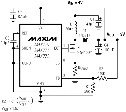
Simplified, the stabilization process looks like this. Resistors R1 and R2 are dividers of the output voltage of the microcircuit; as soon as the divided voltage supplied to the FB pin of the MAX771 microcircuit is greater than the reference voltage (1.5V), the microcircuit reduces the output voltage and vice versa - if the voltage at the FB pin is less than 1.5V, the microcircuit increases the input voltage.
Obviously, if the control circuits are changed so that the MAX771 reacts to (and accordingly regulates) the output current, then we have a regulated current source.
Below is a modified circuit with output voltage limitation and a load case.
At light load, as long as the voltage drop across the current-measuring resistor R3 is less than 1.5V, the circuit in Fig. 10a works as a voltage stabilizer, stabilizing the voltage at the level of the zener diode VD2 + 1.5V. As soon as the load current becomes large enough, the voltage drop across R3 increases and the circuit goes into current stabilization mode.
Resistor R8 is installed if the stabilization voltage can be high - more than 16.5V. Resistor R3 is current-setting and is calculated by the formula: R3 = 1.5/Ist.
The disadvantage of the circuit is the rather large voltage drop across the current-measuring resistor R3. This drawback is eliminated by using an operational amplifier (op-amp) to amplify the signal from resistor R3. For example, if a resistor needs to be reduced by a factor of 10 at a given current, then the op-amp amplifier must amplify the voltage dropped across R3 by a factor of 10 as well.
Conclusion
So, several circuits performing the function of current stabilization were considered. Of course, these circuits can be improved by increasing speed, accuracy, etc. You can use specialized microcircuits as a current sensor and make heavy-duty control elements, but these circuits are ideal in cases where you need to quickly create a tool to make your work easier or solve a certain range of problems.
In this article we’ll talk about another car charger. We will charge the batteries with a stable current. The charger circuit is shown in Figure 1.
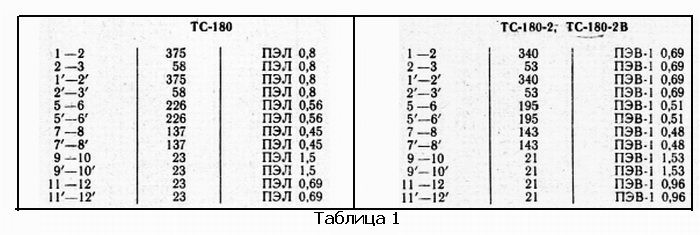
The circuit uses a rewound transformer from a TS-180 tube TV as a network transformer, but TS-180-2 and TS-180-2V are also suitable. To rewind the transformer, we first carefully disassemble it, not forgetting to note which sides the core was glued together with; the position of the U-shaped parts of the core must not be confused. Then all secondary windings are wound up. If you use the charger only at home, you can leave the shielding winding. If the device is intended to be used in other conditions, the shielding winding is removed. The top insulation of the primary winding is also removed. After this, the coils are impregnated with bakelite varnish. Of course, impregnation in production takes place in a vacuum chamber, if there is no such possibility, then we impregnate it using the hot method - into hot varnish heated in a water bath, throw the coils and wait for an hour until they are saturated with varnish. Then we let the excess varnish drip off and put the coils in gas oven with a temperature of about 100... 120˚С. In extreme cases, the winding of the coils can be impregnated with paraffin. After this, we restore the insulation of the primary winding with the same paper, but also impregnated with varnish. Next, we wind on the reels according to... now let's do the math. To reduce current idle speed, and it will clearly increase, since we do not have the necessary ferropaste for gluing twisted and split cores; we will use all the turns of the coil windings. So. The number of turns of the primary winding (see table) is 375+58+375+58 = 866 turns. The number of turns per volt is equal to 866 turns divided by 220 volts, we get 3.936 ≈ 4 turns per volt.
We calculate the number of turns of the secondary winding. Let's set the voltage of the secondary winding to 14 volts, which will give us a voltage of 14 √2 = 19.74 ≈ 20 volts at the output of the rectifier with filter capacitors. In general, the lower this voltage, the less useless power in the form of heat will be released on the transistors of the circuit. And so, we multiply 14 volts by 4 turns per volt, we get 56 turns of the secondary winding. Now let's set the current of the secondary winding. Sometimes you need to quickly recharge the battery, which means you need to increase it for a while charging current to the limit. Knowing the overall power of the transformer - 180 W and the voltage of the secondary winding, we will find the maximum current 180/14 ≈ 12.86 A. The maximum collector current of the KT819 transistor is 15A. Maximum power according to the reference book for this transistor in a metal case, it is 100W. This means that with a current of 12A and a power of 100W, the voltage drop across the transistor cannot exceed... 100/12 ≈ 8.3 volts, and this is provided that the temperature of the transistor crystal does not exceed 25˚C. This means a fan is needed, since the transistor will operate at the limit of its capabilities. We choose a current equal to 12A, provided that each arm of the rectifier will already have two 10A diodes. According to the formula:
We multiply 0.7 by 3.46, we get the wire diameter? 2.4 mm.
You can reduce the current to 10A and use a wire with a diameter of 2mm. To facilitate the thermal regime of the transformer, the secondary winding can not be covered with insulation, but simply covered with an additional layer of bakelite varnish.
KD213 diodes are installed on 100x100x3mm aluminum plate radiators. They can be installed directly on the metal body of the charger through mica spacers using thermal paste. Instead of 213-x, you can use D214A, D215A, D242A, but diodes KD2997 with any letter are best suited, the typical value of the forward voltage drop for which is 0.85V, which means that with a charge current of 12A, heat will be released on them in the form of 0.85 12 = 10W. Maximum straightened D.C. These diodes are 30A, and they are not expensive. The LM358N microcircuit can work with input signal voltages close to zero; I have not seen any domestic analogues. Transistors VT1 and VT2 can be used with any letters. A strip of tinned tin was used as a shunt. The dimensions of my strip cut from tin can() – 180×10x0.2mm. With the values of resistors R1,2,5 indicated in the diagram, the current is regulated in the range from approximately 3 to 8A. The lower the value of resistor R2, the greater the stabilization current of the device. Read how to calculate the additional resistance for a voltmeter.
About the ammeter. My strip, cut to the dimensions indicated above, quite by chance has a resistance of 0.0125 Ohm. This means that when a current of 10A passes through it, U=I R = 10 0.0125=0.125V = 125 mlV will drop across it. In my case, the used measuring head has a resistance of 1200 Ohms at a temperature of 25˚C.
Lyrical digression. Many radio amateurs, thoroughly adjusting the shunts for their ammeters, for some reason never pay attention to temperature dependence all elements of the circuits they assemble. We can talk about this topic ad infinitum, I’ll just give you small example. Here is the active resistance of the frame of my measuring head at different temperatures. And for what conditions should the shunt be calculated?
This means that the current measured at home will not correspond to the current measured by the ammeter in a cold garage in winter. If you don’t care, then just make a switch for 5.5A and 10... 12A and not any devices. And don’t be afraid of breaking them, this is another big plus of a charger with charge current stabilization.
And so on. With a frame resistance of 1200 Ohms and a total deflection current of the device needle of 100 μA, we need to apply a voltage of 1200 0.0001 = 0.12 V = 120 mlV to the head, which is less than the voltage drop across the shunt resistance at a current of 10 A. Therefore, install an additional resistor in series with the measuring head, preferably a tuning one, so as not to have to worry about the selection.
The stabilizer is mounted on a printed circuit board (see photo 3). I limited the maximum charge current for myself to six amperes, therefore, with a stabilization current of 6A and a voltage drop across a powerful transistor of 5V, the released power is 30W, and blown by a fan from the computer, this radiator heats up to a temperature of 60 degrees. With a fan this is a lot, a more efficient radiator is needed. Approximately determine what is needed. My advice to you all is to install radiators designed for the operation of PP devices without coolers, let better sizes the device will increase, but when this cooler is stopped, nothing will burn.

When analyzing the output voltage, its oscillogram was very noisy, which indicates instability of the circuit, i.e. the circuit was excited. It was necessary to supplement the circuit with capacitor C5, which ensured stable operation of the device. Yes, also, in order to reduce the load on the KT819, I reduced the voltage at the rectifier output to 18V (18/1.41 = 12.8V, i.e. the voltage of the secondary winding of my transformer is 12.8V). Download drawing printed circuit board. Goodbye. K.V.Yu.